Advertisement
Table of Contents
- 1 Table of Contents
- 2 Introduction
- 3 Installation
- 4 Hardware Specification Detail
- 5 REF NO: M82/Om/101 Issue no
- 6 Front and Back Panel Description
- 7 Key Function Description
- 8 Menu Layout
- 9 Parameter Flow Chart
- 10 Relay Outputs
- 11 Calibration Procedure
- 12 Modbus Communication Detail
- 13 Miscellaneous
- Download this manual
Advertisement
Table of Contents

Summary of Contents for Masibus Automation And Instrumentation 8204
- Page 1 USER MANUAL 8204 4 - CHANNEL SCANNER Masibus Automation And Instrumentation Pvt. Ltd. B/30, GIDC Electronics Estate, Sector-25, Gandhinagar-382044, Gujarat, India Email: support@masibus.com Web: www.masibus.com...
-
Page 2: Table Of Contents
4-CHANNEL SCANNER-8204 REF NO: m82/om/101 Issue NO: 09 Contents Introduction……………………………………………………………………… (03) Installation……………………………………………………………………….. (05) Hardware Specification Detail……………………………………………… (08) Front and Back Panel Description…………………………………………. (11) Key Function Description…………………………………………………….. (13) Menu Layout………………………………………………………………………. (14) Parameter Flow Chart…………………………………………………………...(22) Relay Outputs…………………………………………………………………….. (25) Calibration Procedure…………………………………………………………… (32) (10) Modbus Communication Detail……………………………………………… (34) (11) Miscellaneous………………………………………………………………………... -
Page 3: Introduction
Trademarks Our product names or brand names mentioned in this manual are the trademarks or registered trademarks of Masibus Automation and Instrumentation (P) Ltd. (herein after referred to as MASIBUS). Adobe, Acrobat, and Postscript are either registered trademarks or trademarks of Adobe Systems Incorporated. - Page 4 , c on t act y ou r s al e s r ep r e s en t ati ve . Product Ordering Code The 8204 Scanner unit has a nameplate affixed to the one side of the enclosure. Check the model and suffix codes inscribed on the nameplate to confirm that the product received is that which was ordered.
-
Page 5: Installation
4-CHANNEL SCANNER-8204 REF NO: m82/om/101 Issue NO: 09 2. INSTALLATION: How to Install: Mounting method: Panel mounting To install the controller select a location where: o no one may accidentally touch the terminals o mechanical vibrations are minimal o corrosive gas is minimal o temperature can be maintained at about 25˚C to 35˚C and the... - Page 6 4-CHANNEL SCANNER-8204 REF NO: m82/om/101 Issue NO: 09 External Dimensions and Panel Cutout Dimensions: FRONT BEZEL: 48 x 96 mm PANEL CUTOUT: 45+0.8(H) x 92+0.8(W) mm DEPTH BEHIND THE PENAL: 130 mm User‟s Manual - 6 -...
- Page 7 4-CHANNEL SCANNER-8204 REF NO: m82/om/101 Issue NO: 09 How to connect wires: Before carrying out wiring, turn off the power to the controller and check that the cables to be connected are not alive with a tester or the like because there is a possibility of electric shock.
-
Page 8: Hardware Specification Detail
4-CHANNEL SCANNER-8204 REF NO: m82/om/101 Issue NO: 09 3. Hardware Specification Detail: Input type: Universal input type Thermocouple, RTD, Millivolt, Voltage, Current INPUT types are software selectable. Applicable Standards: DIN (ITS-90) for Thermocouple and RTD T yp e R an g e... -
Page 9: Ref No: M82/Om/101 Issue No
4-CHANNEL SCANNER-8204 REF NO: m82/om/101 Issue NO: 09 Input Impedance: >1 Mohm for thermocouple/ mV/RTD/Volts inputs Noise Rejection Ratio: NMRR (Normal mode rejection ratio) > 40 dB (50/60 Hz) or more CMRR (Common mode rejection ratio) > 120 dB (50/60 Hz) or more Allowable wiring resistance for RTD: Maximum 15 ohms/wire (Conductor resistance between three wires should be equal). - Page 10 4-CHANNEL SCANNER-8204 REF NO: m82/om/101 Issue NO: 09 Insulation resistance: 20Mohms or more at 500V DC *P ri ma ry t e rmi n al s i n di cat e p ow e r t e rmi n al s a n d r el a y ou t p u t t e rmi n al s **S e c on da r y t e rmi n al s i n di cat e an al og I /O si gn al s , C om mu n i cati on Si gn al s.
-
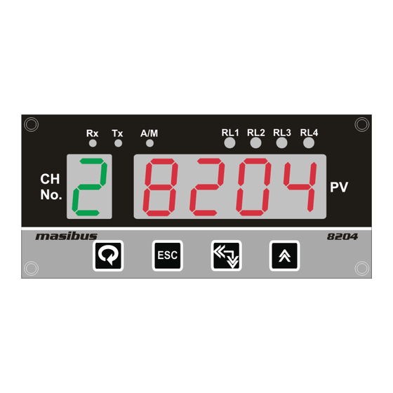
Page 11: Front And Back Panel Description
4-CHANNEL SCANNER-8204 REF NO: m82/om/101 Issue NO: 09 4. Front and Back Panel Description: FRONT PANEL Name of Part Function Process Value Displays Process Value. Display(DATA window) Display Parameter Name When You Set Parameter. Displays Error Message When An Error Occurs. - Page 12 4-CHANNEL SCANNER-8204 REF NO: m82/om/101 Issue NO: 09 BACK PLATE CONNECTION DETAIL: User‟s Manual - 12 -...
-
Page 13: Key Function Description
4-CHANNEL SCANNER-8204 REF NO: m82/om/101 Issue NO: 09 5. Key Function Description: MENU/ENTER KEY: It is used to enter in the sub menu (various levels) and save the parameters to nonvolatile memory, when user setting a proper data by Increment and shift key for parameter configuration. -
Page 14: Menu Layout
4-CHANNEL SCANNER-8204 REF NO: m82/om/101 Issue NO: 09 6. Menu Layout: RUN TIME INDICATION: Following parameters can view or change during run time. Immediately after powering, unit will run in Auto Mode. In auto mode channel will scan automatically according to scan time selection (1-250 second). - Page 15 4-CHANNEL SCANNER-8204 REF NO: m82/om/101 Issue NO: 09 LE VEL 2 :- Pressing MENU key DATA window shows LvL2 (LvL2) message. Press MENU key again DATA window shows pwd (PWD) message, press increment key twice to select password and then press MENU key to enter into Level-2.
- Page 16 4-CHANNEL SCANNER-8204 REF NO: m82/om/101 Issue NO: 09 Rel a y m appi n g Se e R el ay Re f e r Rl . mp Rl . oP (Appl i cabl e f o r 1 Co n fi gu rati on N ot e: 3 (rl.mp)
- Page 17 4-CHANNEL SCANNER-8204 REF NO: m82/om/101 Issue NO: 09 Relay Group - 4: If relay group – 4 is selected, there will be four group of all 4 relays. Each group has one relay. (G -1, G -2, G -3 and G -4).
- Page 18 4-CHANNEL SCANNER-8204 REF NO: m82/om/101 Issue NO: 09 LEVEL – 3: Pressing MENU key DATA window shows LvL3 (LvL3) message. Press MENU key again DATA window shows pwd (PWD) message, press increment key twice to select password and then press MENU key to enter into Level-3.Following parameters can be configured in LEVEL –...
- Page 19 4-CHANNEL SCANNER-8204 REF NO: m82/om/101 Issue NO: 09 up / DoWn RT . o . S Ret r as mi s si on 0:D O WN (rt.o.s) Op en s en s o r 1:UP 0-20/4-20/ 0-5v/1-5v/ Rt . tp 0-10v (rt.tp)
- Page 20 4-CHANNEL SCANNER-8204 REF NO: m82/om/101 Issue NO: 09 Ret r an smi s si on D ep en di n g on v ol tag e an d Rtr . S Ret r as mi s si on typ e cu r r en t Spa n (rtr.S)
- Page 21 4-CHANNEL SCANNER-8204 REF NO: m82/om/101 Issue NO: 09 INPUT TYPE SELECTION TABLE: I /P T yp e T yp e R an g e Re s ol ut i on Di s p l ay - 200 t o E Tc 1000 C...
-
Page 22: Parameter Flow Chart
4-CHANNEL SCANNER-8204 REF NO: m82/om/101 Issue NO: 09 7. Parameter FLOW CHART: 4 Channel Scanner-8204 has a number of software parameters which may or may not be required depending on your particular applications. Display Run Mode Move to Next Page... - Page 23 4-CHANNEL SCANNER-8204 REF NO: m82/om/101 Issue NO: 09 Move to Next Page. LVL2 LVL3 0000 0000 rtrd 0000 0000 0000 SPwd 0000 inPt SkiP PvHi rLLH CALZ PvLo rLGP CALS SCAn rtrZ rLLG ACJC rtrS rLoP FCJC rLFn Srno rLdL...
- Page 24 4-CHANNEL SCANNER-8204 REF NO: m82/om/101 Issue NO: 09 FrSt 0000 0000 LdEF CLAL CLAL PArA Procedure for changing/setting different values to different channels in all levels is shown in the level 1 Hysteresis setting. “see Hys settings” User‟s Manual - 24 -...
-
Page 25: Relay Outputs
4-CHANNEL SCANNER-8204 REF NO: m82/om/101 Issue NO: 09 8. Relay Outputs: Following function can be set for Relay outputs. Relay Logic (Direction): Relay Logic means Relay contact can be changed from Open to Close OR Close to Open. If relay logic is selected Normal, when Fault occur Relay contact will change from Close to Open. - Page 26 4-CHANNEL SCANNER-8204 REF NO: m82/om/101 Issue NO: 09 Relay logic table: ALARM 1 MOMEMTARY ALARM (when in abnormal condition ack not pressed) CONDITION NORMAL ABNORMAL UP (O/S) DOWN (O/S) ACK ** NORMAL * ACK *** LAMP STEADY STEADY STEADY ALARM LATCH...
- Page 27 4-CHANNEL SCANNER-8204 REF NO: m82/om/101 Issue NO: 09 ALARM AL1 MAINTAINED ALARM (when in abnormal condition ack is pressed) DOWN CONDITION NORMAL ABNORMAL UP (O/S) (O/S) ACK ** NORMAL * ACK *** LAMP STEADY STEADY STEADY STEADY ALARM LATCH RELAY...
- Page 28 4-CHANNEL SCANNER-8204 REF NO: m82/om/101 Issue NO: 09 NOTE: * means normal condition after abnormal has occurred ** means ack pressed in abnormal condition *** means ack pressed in normal condition after abnormal has already occurred. **** means it remains in the previous state. If previous state is ON then it will remain ON and the same case for OFF condition.
- Page 29 4-CHANNEL SCANNER-8204 REF NO: m82/om/101 Issue NO: 09 RELAY GROUP - 2 User‟s Manual - 29 -...
- Page 30 4-CHANNEL SCANNER-8204 REF NO: m82/om/101 Issue NO: 09 RELAY GROUP - 1 User‟s Manual - 30 -...
- Page 31 ON after nearly few seconds (as per relay delay) and it will be ON until process value goes up toward Set point. NOTE:- 8204 has both Control Logic (ON-OFF) & Alarm Logic. If Control Logic (ON- rloP OFF) is required, in lvl2 must be selected as Co .
-
Page 32: Calibration Procedure
4-CHANNEL SCANNER-8204 REF NO: m82/om/101 Issue NO: 09 9. Calibration Procedure:- Calibration is provided for ambient temperature, PV sensor input, Retransmission output. First select the calibration function as described below and then follow the procedure depending on the parameter to be calibrated. The sequences of parameters that will be available for calibration are listed below: ... - Page 33 4-CHANNEL SCANNER-8204 REF NO: m82/om/101 Issue NO: 09 In case, the controller cannot complete the calibration due to any reason, it will hold previous calibration parameters. Calibration for input sensor is over. Retransmission output calibration (Voltage/current output) (Optional):- Press MENU key repeatedly, till DATA window shows message rtr.Z (retransmission output zero calibration).
-
Page 34: Modbus Communication Detail
4-CHANNEL SCANNER-8204 REF NO: m82/om/101 Issue NO: 09 10. Communication: The MODBUS Communications protocol as RS-485 interface module is installed. Only RTU mode is supported. Data is transmitted as 8-bit binary bytes with 1 start bit, 1/2 stop bit and optional parity checking (None, Even, Odd). Baud rate may be set to 9600 and 19200. - Page 35 4-CHANNEL SCANNER-8204 REF NO: m82/om/101 Issue NO: 09 Modbus Parameter Details for Input Register: Parameter Absolute Parameter Acces Refer Address Type Value Value Table Type SP.1 CH – 1 40001 SP.1 CH – 2 40002 SP.1 CH – 3 40003 SP.1 CH –...
- Page 36 4-CHANNEL SCANNER-8204 REF NO: m82/om/101 Issue NO: 09 RLY-OpenSensor.3 40052 RLY-OpenSensor.4 40053 RLY-Map CH - 1 40054 T-6/7/8 RLY-Map CH - 2 40055 T-6/7/8 RLY-Map CH - 3 40056 T-6/7/8 RLY-Map CH - 4 40057 T-6/7/8 RLY-Type.1 40058 T-9/10 RLY-Type.2...
- Page 37 4-CHANNEL SCANNER-8204 REF NO: m82/om/101 Issue NO: 09 Span Calibration 49012 Channel-2 Span Calibration 49013 Channel-3 Span Calibration 49014 Channel-4 Unused 49015 Unused 49016 Unused 49017 Unused 49018 Modbus Parameter Details for Read Output Status Register: Parameter Absolute Parameter Access Type...
- Page 38 4-CHANNEL SCANNER-8204 REF NO: m82/om/101 Issue NO: 09 INPUT TYPE SELECTION TABLE :( T – 1) Input Type I/P no Type Zero Span Resolution Display -200 1000 0.1°C E tc -200 1200 0.1°C J tc -200 1370 0.1°C K tc -200 0.1°C...
- Page 39 4-CHANNEL SCANNER-8204 REF NO: m82/om/101 Issue NO: 09 Relay Type for Group – 4 and 1 (T - 9): Relay Type for Group – 2(T – 10): Modbus Index Parameter Value Modbus Index Parameter Value Low ON High/Very High High ON...
-
Page 40: Miscellaneous
4-CHANNEL SCANNER-8204 REF NO: m82/om/101 Issue NO: 09 11. MISCELLANEOUS PV INPUT STATUS DISPLAY DURING BURNOUT CONDITION: Input type Display Message TC-E oPEn OPEN( TC-J OPEN TC-K OPEN TC-T OPEN TC-N OPEN TC-B OPEN TC-R OPEN TC-S OPEN PT 100(RTD) - Page 41 4-CHANNEL SCANNER-8204 REF NO: m82/om/101 Issue NO: 09 RETRAMISSION OUTPUT TABLE FOR OPEN /OVER /UNDER CONDITION: RETRASMISSION VARIABLE SCALE ACTION OPEN OVER UNDER ERROR 4-20mAmp 20.8 20.8 DOWN 20.8 20.8 20.8 DOWN 20.8 Table 2 NOTE: - 1) For Retransmission output type 0-20mAmp, 0-10v, 1-5v and 0-5v also applicable according to above table.
Need help?
Do you have a question about the 8204 and is the answer not in the manual?
Questions and answers