Advertisement
Quick Links
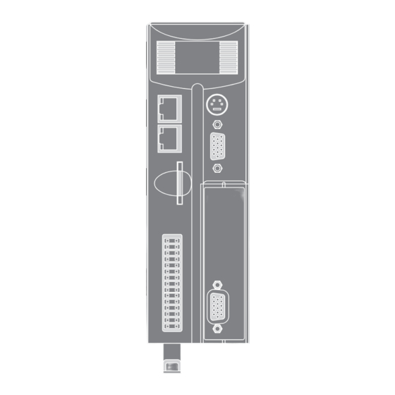
BACKLIT DISPLAY
RS232 + RS485
COMMON EARTHING
FOR IMPROVED
NOISE REJECTION
ETHERNET
PROGRAMMING
SYNC ENCODER
SD CARD
I/O, CAN, POWER,
ANALOGUE
EASY RELEASE
EXPANSION COVER
FIRST EXPANSION
MODULE
MOTION COORDINATOR
MC464
Quick Connection Guide
(Please refer to the Motion Coordinator Technical Reference Manual 7 for Full Details)
Advertisement

Subscribe to Our Youtube Channel
Related Manuals for Trio MC464


Summary of Contents for Trio MC464
- Page 1 FOR IMPROVED NOISE REJECTION ETHERNET PROGRAMMING SYNC ENCODER SD CARD I/O, CAN, POWER, ANALOGUE EASY RELEASE EXPANSION COVER FIRST EXPANSION MODULE MOTION COORDINATOR MC464 Quick Connection Guide (Please refer to the Motion Coordinator Technical Reference Manual 7 for Full Details)
- Page 2 BACKLIT DISPLAY RS232 + RS485 ETHERNET PROGRAMMING SYNC ENCODER SD CARD FIRST EXPANSION MODULE I/O, CAN, POWER, ANALOGUE...
- Page 3 0V AIN 0V CAN/AIN AIN0 CAN LOW used to provide the 24V dc power AIN1 CAN EARTH to the MC464. A 24V dc, Class 2 WDOG+ CAN HIGH transformer or power source must WDOG- 24V CAN/AIN SUPPLY be provided. I/O8...
-
Page 4: Serial Connections
SERIAL 8 Way MiniDIN Function Note CONNECTIONS RS485 Data In A Rx+ Serial Port #2 RS485 Data In B Rx- RS232 Transmit Serial Port #1 0V Serial RS232 Receive Serial Port #1 Internal 5V RS485 Data Out Z Tx- Serial Port #2 RS485 Data Out Y Tx+ SYNC ENCODER 9 Way D-Type... - Page 5 Replacing the module is the reverse of the procedure. To replace the battery, insert screwdriver under the frontmost ventilation slot (F) and prize off the battery cover (D) and pull the battery ribbon to lift the battery (E) from the MC464. Replacing is the reverse of the procedure.
-
Page 6: Lcd Display
Display with WDOG on ENABLE The IP address and subnet mask of the MC464 is shown on the LCD display for a few seconds after power-up. The factory default IP address is 192.168.0.250. This can be changed using the ETHERNET command via Motion Perfect. - Page 7 A maximum of 7 half height modules or 3 full height modules may be ASSEMBLY fitted to the MC464. A system may be made using any combination of half and full height modules providing that the full height modules are the last to be attached.
- Page 8 EXPANSION MODULE P871 - MC464 PANASONIC INTERFACE REGISTRATION R0 - R7: registration inputs (24V). CONNECTOR R0V: registration common 0V return. Registration inputs can be allocated to any axis by software. Note: This pin out applies to module serial numbers P871-00011 and higher.
-
Page 9: Led Functions
LED FUNCTIONS LED Colour LED Function Green ON=Module Initialised Okay ON=Module Error Yellow Status 1 Yellow Status 2... - Page 10 EXPANSION MODULE P872 - MC464 SERCOS INTERFACE REGISTRATION R0 - R7: registration inputs (24V). CONNECTOR 0V: registration common 0V return. Registration inputs can be allocated to any axis by software. CONNECTOR (TX) sercos fibre-optic transmit. 9mm FSMA CONNECTOR (RX) sercos fibre-optic receive.
- Page 11 LED FUNCTIONS LED LED Colour LED Function Green ON=Module Initialised Okay ON=Ring Open / Distorted Yellow SERCOS Phase Yellow SERCOS Phase SERCOS PHASE LED 1 LED 2 FLASH FLASH...
- Page 12 EXPANSION MODULE P873 - MC464 SLM INTERFACE REGISTRATION R0 - R5: registration inputs (24V). CONNECTOR 0VR: common 0V return. 0V PWR: Power input for SLM system. 24V: 0V PWR SLM CONNECTOR 15 Way D-Type Upper D-Type Lower D-Type Com Axis 0 Com Axis 3 /Com Axis 0.
- Page 13 LED FUNCTIONS LED Colour LED Function Green ON=Module Initialised Okay ON=Module Error Yellow Status 1 Yellow Status 2...
- Page 14 EXPANSION MODULE P874 / P879 - MC464 FLEXIBLE AXIS INTERFACE REGISTRATION V0 - V7: Voltage outputs CONNECTOR R4/PS4 - R7/PS7: Bidirectional registration R0 - R3: Registration In Inputs / 24V: PSwitch outputs 0V PWR: Power Input 24V: Power Input R4/PS4...
-
Page 15: Encoder Connector
ENCODER 15 Way D-Type Incremental Absolute Pulse & CONNECTOR Encoder Encoder Direction Enc. A n Clock n Step.+ n Enc. /A n /Clock n Step.- n Enc. B n -------- Direction+ n Enc. /B n -------- Direction- n 0V Enc. 0V Enc. - Page 16 (C) on the lower front edge of the Anybus® module locate under the P875 PCB at the front. When the module is flush with the face of the Trio Expansion Interface, tighten the two “Torx” head screws (D) to locate the two lugs (E) and secure the Anybus®...
- Page 17 EXPANSION MODULE P876 - MC464 ETHERCAT INTERFACE REGISTRATION R0 - R7: registration inputs (24V). CONNECTOR 0V: registration common 0V return. Registration inputs can be allocated to any axis by software. RJ45 100 base-T Ethernet master. Connect to IN of CONNECTOR...
- Page 18 LED FUNCTIONS LED Colour LED Function Green ON=Module Initialised Okay ON=Module Error Yellow Status 1 Yellow Status 2...
Need help?
Do you have a question about the MC464 and is the answer not in the manual?
Questions and answers