Table of Contents
Advertisement
Quick Links
Advertisement
Table of Contents
Troubleshooting

Summary of Contents for Terumo BCT Trima Accel
- Page 1 ® Trima Accel Automated Blood Collection System Service Manual...
- Page 2 Trima Accel ® Automated Blood Collection System Service Manual Part No. 777095-548 2015-09...
- Page 3 ©2015 Terumo BCT, Inc. Terumo BCT is a registered trademark of Terumo Corporation. VxWorks is a registered trademark of Wind River Systems, Inc. Terumo BCT, Inc. 10811 W. Collins Avenue Lakewood, Colorado 80215 USA Phone: +1.877.339.4228 Phone: +1.303.231.4357 USA Fax: +1.866.715.6768 Fax: +1.303.542.5215...
-
Page 4: Table Of Contents
Power System ..............................1-51 Mechanical Systems ............................1-52 2: System Description Pump System ..............................2-2 Pump Assembly ............................2-5 Sensor System ..............................2-7 Pressure Sensors ............................2-8 Reservoir Level Sensors ..........................2-10 Trima Accel Automated Blood Collection System • Service Manual ®... - Page 5 IV Pole ..............................2-70 Wheel and Brake System ......................... 2-71 3: Software Description Version 5.1 Software Description ........................3-2 Trima Accel Software Description ......................3-2 State and Substate Overview ........................3-2 Self Test State ............................3-7 Power Fail Recovery State .......................... 3-9 Startup Tests State .............................
- Page 6 Rinseback State ............................3-33 Donor Disconnect State .......................... 3-35 Post Run State ............................3-37 Version 6.0 Software Description ........................3-38 Trima Accel Software Description ......................3-38 Self Test State ............................3-38 Power Fail Recovery State ........................3-40 Startup Tests State ........................... 3-40 Disposable Tests State ..........................
- Page 7 Anticoagulant (AC) Flow Alarm ........................6-22 Anticoagulant (AC) Ratio Alarm ........................6-23 Anticoagulant (AC) Infusion Alarm ........................6-24 Touch-Screen Display ............................6-25 Symbols and Certification ..........................6-26 Seal Safe System Specifications ......................... 6-29 Index Trima Accel Automated Blood Collection System • Service Manual ®...
-
Page 8: Preface
The Trima Accel Automated Blood Collection System Service Manual provides the information needed to service and troubleshoot the system. This manual applies to versions 5.1.0 and higher. For version 5.0 systems, see the Trima Accel Automated Blood Collection System Service Manual PN 777821-113, RN 704111-003. -
Page 9: How To Use This Manual
Describes the software that the device uses to operate. Alarms Provides alarm text and alarm information. Troubleshooting Describes non-alarm troubleshooting. Maintenance and Describes maintenance and service procedures for the device. Calibration Trima Accel Automated Blood Collection System • Service Manual ®... -
Page 10: 1: Operational Description
Operational Description Trima Accel Automated Blood Collection System • Service Manual ®... -
Page 11: System Directory
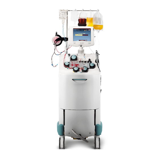
Operational Description System Directory The Trima Accel system consists of several major subsystems, such as the display, the pump panel, the centrifuge chamber, and the electronics box (e-box). The system directory shows the names and locations of some major systems and components in relation to the whole device. - Page 12 18 Loop damper 19 Handheld barcode reader outlet 20 Side panel 21 Front panel 22 Rear panel 23 Linear actuator screw access hole Figure 1-1: The Trima Accel system, front view Trima Accel Automated Blood Collection System • Service Manual ®...
- Page 13 18 Loop damper 19 Handheld barcode reader outlet 20 Side panel 21 Front panel 22 Rear panel 23 Linear actuator screw access hole Figure 1-2: The Trima Accel system, rear view Trima Accel Automated Blood Collection System • Service Manual ®...
- Page 14 System Directory Table 1-1: Trima Accel system components Component Function Display Allows you to communicate with the system through audio, visual, or touch- screen interfaces. IV pole Contains hooks for hanging bags and containers. Adjusts up and down for transport.
- Page 15 Operational Description Table 1-1: Trima Accel system components (continued) Component Function Rear panel Covers and protects the internal components from damage, holds the power cord, vents heat from inside the device, and allows access to the screw that is used to manually raise the cassette plate (used during power failure).
- Page 16 5 E-box cooling fan 3 (inside e-box) 6 Linear actuator screw 7 Leak detector CCA 8 Top cap assembly 9 ESD service strap Figure 1-3: The Trima Accel system with no panels, front view Trima Accel Automated Blood Collection System • Service Manual ®...
- Page 17 5 E-box cooling fan 3 (inside e-box) 6 Linear actuator screw 7 Leak detector CCA 8 Top cap assembly 9 ESD service strap Figure 1-4: The Trima Accel system with no panels, rear view Trima Accel Automated Blood Collection System • Service Manual ®...
- Page 18 System Directory Table 1-2: Trima Accel system components Component Function Centrifuge motor Spins the disposable tubing set channel that is used to separate blood into its components. E-box Contains CCAs for the safety and control systems, the hard drive, the motor drive systems, and the power supply.
- Page 19 2 Basin 3 Leak detector 4 Filler assembly 5 Upper hex holder 6 Door lock with sensors Figure 1-5: The Trima Accel basin Table 1-3: Trima Accel basin components Component Function Centrifuge Spins the disposable tubing set channel that is used to separate blood into its components.
-
Page 20: Boot Sequence
This section describes the boot sequence and when to interrupt that sequence for troubleshooting and maintenance purposes. When it is turned on, the Trima Accel device performs a low-level memory check, generating an alarm if this check fails. If this check is successful, the device moves on to the boot sequence. -
Page 21: Blood Collection Process
Figure 1-6: Trima Accel fluid flow diagram First, the disposable tubing set is loaded onto the Trima Accel system. Once the cassette is loaded, the Trima Accel system prompts the operator to clamp both the needle line and the sample bag line. The anticoagulant (AC), return, and inlet pumps are run to pressure test the tubing set. - Page 22 The control and safety computers monitor several items during startup of the procedure. The first return cycle is monitored closely due to the high amount of AC in the Trima Accel system during startup. An over-delivery of volume during the first return cycle results in a safety shutdown of the Trima Accel system for this reason.
-
Page 23: Pump System
Operational Description Pump System The Trima Accel device uses five pumps to move anticoagulant, blood, and blood components through the disposable tubing set using peristaltic action. Each pump consists of a pump motor, a pump rotor, a seal, and a raceway housing. The platelet pump spins at a significantly slower rate than the rest of the pumps, so it needs two magnets in the rotor to properly measure speed. - Page 24 Pump System 1 AC pump (behind IV pole) 2 Inlet pump 3 Return pump 4 Plasma pump 5 Platelet pump Figure 1-8: Pump locations (rear) Trima Accel Automated Blood Collection System • Service Manual 1-15 ®...
- Page 25 Turns the rotor to move fluids through the disposable tubing set. Drive terminals Connect the pump to 24 V power. Encoder connector Sends pump speed encoder data from the pump motor to the e-box. 1-16 Trima Accel Automated Blood Collection System • Service Manual ®...
- Page 26 Prevents fluid from entering the device. It is a rubber seal between the pump motor shaft and the pump raceway housing. Hall-effect sensor Senses pump speed by detecting when the magnet in the pump rotor passes over Trima Accel Automated Blood Collection System • Service Manual 1-17 ®...
- Page 27 The platelet pump rotor (indicated with a dot on the rotor cap) is the only rotor with two magnets; all of the other rotors have only one magnet. Rotor washer Decreases clicking noises during rotation. It is a clear plastic washer. 1-18 Trima Accel Automated Blood Collection System • Service Manual ®...
-
Page 28: Sensor System
There are closed loop and open loop conditions to the feedback systems. Closed loop is the default condition that uses sensor-derived feedback to directly control the system. An open loop condition removes the sensor-derived information from the feedback loop. Trima Accel Automated Blood Collection System • Service Manual 1-19... -
Page 29: Pressure Sensors
Operational Description Pressure Sensors There are two pressure sensors on the front panel of the Trima Accel system, which monitor the draw/ return donor access pressure and the centrifuge pressure. 1 Access/return pressure sensor 2 Centrifuge pressure sensor Figure 1-12: Pressure sensor locations (front) -
Page 30: Ac Sensor
Adapter CCA Connects the pressure sensor connectors to the wiring harness connectors. AC Sensor The anticoagulant (AC) sensor indicates the presence of AC. Figure 1-14: The AC sensor Trima Accel Automated Blood Collection System • Service Manual 1-21 ®... -
Page 31: Reservoir Level Sensors
Figure 1-15: Reservoir level sensor locations (front) 1 Upper-level reservoir sensor 2 Lower-level reservoir sensor (not visible, located behind the linear actuator assembly) Figure 1-16: Reservoir level sensor locations (rear) 1-22 Trima Accel Automated Blood Collection System • Service Manual ®... -
Page 32: Rbc Detector
The RBC detector is also used to identify disposable set type. It can sense whether a black or white stamp is on the cassette. Figure 1-17: RBC detector location (front) Trima Accel Automated Blood Collection System • Service Manual 1-23... - Page 33 Operational Description Figure 1-18: RBC detector location (rear) 1-24 Trima Accel Automated Blood Collection System • Service Manual ®...
-
Page 34: Leak Detector
Sensor System Leak Detector The leak detector is a resistive sensor used to detect leaks in the centrifuge basin. Figure 1-19: The fluid leak detector Trima Accel Automated Blood Collection System • Service Manual 1-25 ®... - Page 35 Operational Description Figure 1-20: The fluid leak detector connection and the leak detector CCA (rear) 1-26 Trima Accel Automated Blood Collection System • Service Manual ®...
-
Page 36: Centrifuge System
13 Power cable 14 Centrifuge Hall-effect sensor cable 15 Precession damper pin 16 Precession damper 17 Ground strap 18 Centrifuge motor controller 19 64 V switch Figure 1-21: Centrifuge assembly components Trima Accel Automated Blood Collection System • Service Manual 1-27 ®... - Page 37 13 Power cable 14 Centrifuge Hall-effect sensor cable 15 Precession damper pin 16 Precession damper 17 Ground strap 18 Centrifuge motor controller 19 64 V switch Figure 1-22: Centrifuge system components 1-28 Trima Accel Automated Blood Collection System • Service Manual ®...
- Page 38 Provides a connection point for the disposable tubing set’s lower bearing to attach to the loop arm. Gear shrouds Cover and protect the gear assembly of the centrifuge. These shrouds can be removed for cleaning. Trima Accel Automated Blood Collection System • Service Manual 1-29 ®...
- Page 39 Provides a common ground point between the centrifuge assembly and the device chassis. Centrifuge motor Provides 3-phase power signals to the centrifuge motor. controller 64 V switch Controls the power available to the centrifuge motor. 1-30 Trima Accel Automated Blood Collection System • Service Manual ®...
-
Page 40: Filler Assembly
Collar holder centrifuge spins. Swings up to facilitate loading of the channel. The filler latch lowers Filler latch over the filler latching pin to lock the filler in place. Trima Accel Automated Blood Collection System • Service Manual 1-31 ®... -
Page 41: Door System
Spring-loaded plate that is moved by the door latch handle. This plate holds the latch magnet and the locking shaft hole and provides a surface that is used to activate the door closed plunger. 1-32 Trima Accel Automated Blood Collection System • Service Manual ®... - Page 42 1 Door position Hall- effect sensor 2 Door lock solenoid 3 Solenoid position optical sensor 4 Locking shaft 5 Door position optical sensor Figure 1-27: Door lock component locations with covers Trima Accel Automated Blood Collection System • Service Manual 1-33 ®...
- Page 43 Door lock solenoid Engages the locking shaft that locks the centrifuge door closed using a momentary 24 V bi-directional pulsed signal. 1-34 Trima Accel Automated Blood Collection System • Service Manual ®...
- Page 44 Senses the open or closed position of the centrifuge door. A spring-loaded plunger sensor interacts with the centrifuge door, and the sensor determines this state when a flag attached to the plunger interrupts the light. Trima Accel Automated Blood Collection System • Service Manual 1-35 ®...
-
Page 45: Valve System
The valves are used to divert blood components to collection bags or back to the donor. Valve Locations 1 RBC valve 2 Plasma valve 3 Platelet valve 4 Valve housing Figure 1-30: Valve locations (front) 1-36 Trima Accel Automated Blood Collection System • Service Manual ®... - Page 46 Provides a surface for the valve rollers to compress the tubing against. It provides a base to which the valve assembly can be mounted and includes stop pins that limit valve rotation. Trima Accel Automated Blood Collection System • Service Manual 1-37...
- Page 47 Valve housing stop pin Provides a stopping point that inhibits valve rotation when the valve reaches functional limits. 1-38 Trima Accel Automated Blood Collection System • Service Manual ®...
- Page 48 Function Valve post Pinches the tubing lines closed by pressing against the valve housing surface. Valve post bearing Rotates to help pinch the tubing lines closed without damaging them. Trima Accel Automated Blood Collection System • Service Manual 1-39 ®...
- Page 49 Contains the optical sensors mounted on the CCA and pass-through circuitry for the cassette position sensors. Valve O-ring seal Prevents fluid from entering the electronics inside the device. Valve assembly connector Connects the valve assembly to the e-box. 1-40 Trima Accel Automated Blood Collection System • Service Manual ®...
-
Page 50: Linear Actuator
6 Lead screw drive nut 7 Sensor flag 8 Tie bar shafts 9 Cassette plate 10 Raised cassette position sensor 11 Lowered cassette position sensor Figure 1-35: The cassette plate Trima Accel Automated Blood Collection System • Service Manual 1-41 ®... - Page 51 This sensor connects to J3 (the right-side connector, as viewed from the rear of the device) on the valve CCA. 1-42 Trima Accel Automated Blood Collection System • Service Manual ®...
-
Page 52: E-Box
16 Power receptacle 17 Power cord clamp (not shown) 18 Service Ethernet port 19 High frequency filter 20 General line filter 21 E-box cover (not shown) Figure 1-36: E-box components Trima Accel Automated Blood Collection System • Service Manual 1-43 ®... - Page 53 Responsible for operator, procedure, and hardware control. Control computer Responsible for operator, procedure, and hardware control and communicates with the safety computer to make sure they are within safe limits. 1-44 Trima Accel Automated Blood Collection System • Service Manual ®...
- Page 54 Removes electrical noise from the input AC power. E-box cover (not Provides physical and ESD protection to the electronics in the e-box. The foam pictured) backing on the cover presses on the CCAs, preventing intermittent connections. Trima Accel Automated Blood Collection System • Service Manual 1-45 ®...
- Page 55 9 Keyboard connector 10 Hard drive 11 Centrifuge motor controller 12 DC power supply 13 64 V switch CCA 14 E-box fan Figure 1-38: The Trima Accel system e-box 1-46 Trima Accel Automated Blood Collection System • Service Manual ®...
-
Page 56: Display System
13 Display arm 14 Display arm cable 15 Display CCA 16 Flex harness 17 LED power cable 18 Grounding straps 19 Display plate 20 Speaker Figure 1-39: Display components (front) Trima Accel Automated Blood Collection System • Service Manual 1-47 ®... - Page 57 13 Display arm 14 Display arm cable 15 Display CCA 16 Flex harness 17 LED power cable 18 Grounding straps 19 Display plate 20 Speaker Figure 1-41: Internal display components (front) 1-48 Trima Accel Automated Blood Collection System • Service Manual ®...
- Page 58 Stop button Stops centrifuge and pump movement when pressed while in Procedure mode. Trima Accel Automated Blood Collection System • Service Manual 1-49 ®...
- Page 59 Display plate Provides a mounting surface for the display components and attaches the display assembly to the display arm. Speaker Generates audio tones for alerts, alarms, and other operational sounds. 1-50 Trima Accel Automated Blood Collection System • Service Manual ®...
-
Page 60: Power System
64 volts is used by the centrifuge motor. There is also a 12.7 volt output for the Seal Safe system, if that is installed. Trima Accel Automated Blood Collection System • Service Manual 1-51 ®... -
Page 61: Mechanical Systems
The front door latch plate is adjustable to ensure a seal with the basin front edge. The body panels are removable to allow access to device systems and parts. There are two side panels, a front panel, and a back panel. 1-52 Trima Accel Automated Blood Collection System • Service Manual ®... -
Page 62: 2: System Description
System Description Trima Accel Automated Blood Collection System • Service Manual ®... -
Page 63: Pump System
1 AC pump 2 Inlet pump 3 Return pump 4 Plasma pump 5 Platelet pump Figure 2-1: Pump locations (front) Trima Accel Automated Blood Collection System • Service Manual ®... - Page 64 The platelet pump is also used to add replacement fluid for the donor during a dRBC run. The platelet pump rotor is not interchangeable with the other rotors. Trima Accel Automated Blood Collection System • Service Manual ®...
- Page 65 CCA. The pump rotations seen by both the safety CCA and the control CCA must agree, otherwise an alarm is generated, and the safety CCA cuts 24-volt power to the motor driver CCA. Trima Accel Automated Blood Collection System • Service Manual...
-
Page 66: Pump Assembly
CCA to the pump motor. Hall-effect sensor The Hall-effect sensor acts as a redundant speed monitor by reporting the pump speed to the safety CCA. The sensor is mounted to the pump raceway. Trima Accel Automated Blood Collection System • Service Manual ®... - Page 67 System Description Figure 2-4: Pump interconnect diagram Trima Accel Automated Blood Collection System • Service Manual ®...
-
Page 68: Sensor System
The sensor system is made up of • Two pressure sensors • Two fluid level sensors • The RBC detector • The AC detector • The leak detector Figure 2-5: Sensors interconnect diagram Trima Accel Automated Blood Collection System • Service Manual ®... -
Page 69: Pressure Sensors
System Description Pressure Sensors The pressure sensors (2) measure access, return, and centrifuge pressures. 1 Access/return pressure sensor 2 Centrifuge pressure sensor Figure 2-6: Pressure sensor locations (front) Trima Accel Automated Blood Collection System • Service Manual ®... - Page 70 The control computer performs analog-to-digital conversion for its processing. The control computer sends that feedback information to adjust the AC, return, and inlet pump speeds. Trima Accel Automated Blood Collection System • Service Manual ®...
-
Page 71: Reservoir Level Sensors
The return cycle starts when both sensors detect fluid. The return pump starts, pumping fluid out of the reservoir. When both sensors detect air, the return pump stops and the draw cycle starts. 2-10 Trima Accel Automated Blood Collection System • Service Manual ®... - Page 72 0.75 to 0.95 E (empty) 0.95 Full with Error Fluid Empty Error 0.75 to 0.15 to 0.55 F (fail) 0.95 * The safety system does not look at the upper-level sensor Trima Accel Automated Blood Collection System • Service Manual 2-11 ®...
- Page 73 24 volts to the motor driver CCA, which removes pump power so the pumps do not run even if commanded to do so by the control system. This prevents air from being returned into the donor. 2-12 Trima Accel Automated Blood Collection System • Service Manual ®...
-
Page 74: Ac Sensor
Figure 2-11: The AC sensor The AC fluid sensor detects the presence of anticoagulant (AC) in the anticoagulant line with an ultrasonic 2 MHz signal. Figure 2-12: AC detector block diagram Trima Accel Automated Blood Collection System • Service Manual 2-13 ®... -
Page 75: Rbc Detector
The RBC detector detects gross differences between the predicted platelet collection and the actual collected platelet product. If a gross difference is detected, the system generates a Verify Platelet Product message at the end of the procedure. 2-14 Trima Accel Automated Blood Collection System • Service Manual ®... -
Page 76: Leak Detector
Above 3.0 V indicates an open circuit. During startup tests and prior to loading a tubing set, the system checks the ability of the leak detector to operate normally. Trima Accel Automated Blood Collection System • Service Manual 2-15 ®... - Page 77 System Description Figure 2-15: The leak detector Figure 2-16: Leak detector block diagram 2-16 Trima Accel Automated Blood Collection System • Service Manual ®...
- Page 78 This leak condition causes the control CCA to remove the 64- volt power to the centrifuge motor, causing the centrifuge to stop. Trima Accel Automated Blood Collection System • Service Manual 2-17...
-
Page 79: Centrifuge System
• The centrifuge contains an open port for loading the disposable channel, which occupies the middle of the gear train hub. Note: The Spectra Optia and Trima Accel centrifuge basins are not interchangeable. 2-18 Trima Accel Automated Blood Collection System • Service Manual... - Page 80 3 Upper collar holder 4 Upper bearing holder 5 Leak detector 6 Centrifuge arm 7 Lower bearing holder 8 Filler 9 Centrifuge loading port Figure 2-17: The centrifuge door and basin Trima Accel Automated Blood Collection System • Service Manual 2-19 ®...
- Page 81 The leak detector plugs into this circuit card and the output of the circuit card goes to the control CCA. 2-20 Trima Accel Automated Blood Collection System • Service Manual ®...
- Page 82 The Hall-effect sensor output is a pulse voltage. If voltage, current, or something in processing is wrong in the CMC, it sends a fault signal (commutation, direction, or processing) to Trima Accel Automated Blood Collection System • Service Manual 2-21 ®...
-
Page 83: Centrifuge Drive Assembly
(Hall-effect feedback) are all columns in the dlog file. Centrifuge braking circuitry is in the CMC. Centrifuge Drive Assembly 1 Gear assembly 2 Centrifuge motor 3 Hall-effect sensor 4 Cooling fan Figure 2-19: The centrifuge drive assembly and motor 2-22 Trima Accel Automated Blood Collection System • Service Manual ®... -
Page 84: Centrifuge Motor Controller
When the centrifuge stops, due to either a command or an alarm condition, the control system and the safety system can command the motor controller to brake the centrifuge motor. Trima Accel Automated Blood Collection System • Service Manual 2-23... - Page 85 System Description Figure 2-20: Centrifuge motor controller (old version) 2-24 Trima Accel Automated Blood Collection System • Service Manual ®...
- Page 86 Centrifuge System Figure 2-21: Centrifuge motor controller (new version) Trima Accel Automated Blood Collection System • Service Manual 2-25 ®...
-
Page 87: Door System
Safety CCA reset of 24 V shutdown (digital) indicates run or no reset (low) • Safety CCA must activate the 24 V DC switch (digital) on the motor driver CCA 2-26 Trima Accel Automated Blood Collection System • Service Manual ®... - Page 88 CCA FPGA through an Ethernet connection. This is a redundant system used to ensure that the device fails in a safe state. An alarm is generated if the safety computer notices a difference between the control and safety conditions. Trima Accel Automated Blood Collection System • Service Manual 2-27...
- Page 89 2-28 Trima Accel Automated Blood Collection System • Service Manual ®...
- Page 90 (optical) and sends this data to the safety computer. The two computers compare this data through an Ethernet connection, and the two sets of sensor data must agree, or an alarm is generated. Trima Accel Automated Blood Collection System • Service Manual 2-29...
- Page 91 T1 test. For certain versions of software, a T1 test failure on the lock solenoid may not have an alarm at the time of failure, but may alarm at the donor connection step instead. 2-30 Trima Accel Automated Blood Collection System • Service Manual ®...
-
Page 92: Valve System
Safety CCA reset of 24 V shutdown (digital) indicates run or no reset (low) • Safety CCA must activate the 24 V DC switch (digital) on the motor driver CCA Trima Accel Automated Blood Collection System • Service Manual 2-31... - Page 93 If the safety computer notices a significant difference between the control and safety conditions, the device is shut down with an alarm or reboot. 2-32 Trima Accel Automated Blood Collection System • Service Manual ®...
- Page 94 +24 V DC is used for clockwise (CW) rotation, -24 V DC is used for counterclockwise (CCW) rotation, and 0 V DC is used to hold position and resist rotation. Trima Accel Automated Blood Collection System • Service Manual 2-33...
- Page 95 The position sensor bit is read by control and safety every 10 ms. This code is also in the dlog file labeled as “valve position.” See the Troubleshooting chapter for more detail on dlogs. 2-34 Trima Accel Automated Blood Collection System • Service Manual ®...
- Page 96 The position sensor LED power is generated on the safety CCA. The FPGA on the safety CCA performs an LED test at start-up and every 60 seconds during a run. The test is as follows: Trima Accel Automated Blood Collection System • Service Manual 2-35 ®...
- Page 97 24-volt switch. The safety computer also monitors the prerequisites and removes power if any of these are missing or incorrect. 2-36 Trima Accel Automated Blood Collection System • Service Manual ®...
-
Page 98: Linear Actuator System
See the operator's manual for details. Slip clutch The slip clutch stops the linear actuator in case of a jam or finger entanglement. Trima Accel Automated Blood Collection System • Service Manual 2-37 ®... - Page 99 The safety CCA removes the control CCA’s command if this occurs. When the control CCA sees zero feedback volts, the drive signals shut off. The fault line is current sense; if the current goes too high, it shuts off the drive voltage. 2-38 Trima Accel Automated Blood Collection System • Service Manual ®...
- Page 100 Linear Actuator System Trima Accel Automated Blood Collection System • Service Manual 2-39 ®...
-
Page 101: E-Box And Computer Systems
9 Keyboard connector 10 Hard drive 11 Centrifuge motor controller 12 DC power supply 13 64 V switch CCA 14 E-box fan Figure 2-29: The Trima Accel system e-box 2-40 Trima Accel Automated Blood Collection System • Service Manual ®... - Page 102 E-Box and Computer Systems Figure 2-30: E-Box interconnect diagram Trima Accel Automated Blood Collection System • Service Manual 2-41 ®...
-
Page 103: Control And Safety Functions
• Pumps • Centrifuge • Valves • Door sensors • Cassette position Figure 2-31: Control and safety communication 2-42 Trima Accel Automated Blood Collection System • Service Manual ®... -
Page 104: Control Cca
On the new control CCA, the 64 V switch is located on a separate circuit board. It is possible to upgrade a machine to the new-style control CCA. Figure 2-32: The control CCA Trima Accel Automated Blood Collection System • Service Manual 2-43... - Page 105 Monitors for the presence of anticoagulant AC air detector Monitors the reservoir level Upper- and lower-level reservoir sensors Monitors centrifuge speed Centrifuge Hall-effect sensors Monitors pump speeds Pump motor encoder signals 2-44 Trima Accel Automated Blood Collection System • Service Manual ®...
- Page 106 The LVDS circuitry multiplexes the 32-TTL (transistor-transistor logic) signals from the control computer into 8 low-voltage differential lines for signal fidelity. The LVDS signals are converted back to TTL signals on the display CCA. Trima Accel Automated Blood Collection System • Service Manual 2-45...
-
Page 107: Control Computer
The control computer boots from the hard disk drive and runs on the VxWorks operating system. The control Ethernet is connected directly to the control computer. The barcode scanner also uses one of the serial ports. Figure 2-33: The control computer 2-46 Trima Accel Automated Blood Collection System • Service Manual ®... -
Page 108: Control Ethernet Cca
The control Ethernet CCA is used to transfer software to the safety computer from the hard drive during the boot sequence. The control and safety Ethernet CCAs are connected using a crossover Ethernet cable. Figure 2-34: The control Ethernet CCA Trima Accel Automated Blood Collection System • Service Manual 2-47 ®... -
Page 109: Safety Cca
The safety CCA also powers the alarm LEDs. Note: The safety CCA is sometimes referred to as the ultrasafe CCA or the ultrasonic CCA. Figure 2-35: The safety CCA 2-48 Trima Accel Automated Blood Collection System • Service Manual ®... - Page 110 CCA, and the physical 64 V switch is located on the 64 V switch CCA. Ultrasonic Circuits The ultrasonic transmitter and receiver circuits for the fluid detectors and the upper-level and lower- level reservoir sensors are housed on the safety/ultrasonics CCA. Trima Accel Automated Blood Collection System • Service Manual 2-49 ®...
-
Page 111: Safety Computer
The safety computer interfaces through the internal network to boot from the hard drive by requesting the data from the control computer. Figure 2-36: The safety computer 2-50 Trima Accel Automated Blood Collection System • Service Manual ®... -
Page 112: Safety Ethernet Cca
ROM on the safety Ethernet CCA. The control computer and safety computer continually exchange information about pump speeds, centrifuge speeds, and motor and valve positions to ensure safe operation. Figure 2-37: The safety Ethernet CCA Trima Accel Automated Blood Collection System • Service Manual 2-51 ®... -
Page 113: Motor Driver Cca
CCA and used for feedback. Redundant Hall-effect sensors are mounted in the raceway housing of each pump. These signals are sent to the safety CCA and monitored to ensure safe limits. 2-52 Trima Accel Automated Blood Collection System • Service Manual ®... - Page 114 This signal is sent back to the control CCA and transferred to the safety CCA for redundant monitoring. When the control computer detects that the cassette plate is in the commanded position, the drive signal is shut off. Trima Accel Automated Blood Collection System • Service Manual 2-53...
-
Page 115: 64 V Switch Cca
Use test points J1 and J2 to measure the power supply 64 V. • Use test points J1 and J3 to measure a quick pulse from the over-voltage protection (OVP) signal. 2-54 Trima Accel Automated Blood Collection System • Service Manual ®... - Page 116 E-Box and Computer Systems Figure 2-40: The 64 V switch CCA Trima Accel Automated Blood Collection System • Service Manual 2-55 ®...
-
Page 117: Cooling Fans
There are three 24 V DC cooling fans. Each fan has a Hall-effect sensor that is monitored by the control CCA. If the fan has stopped or the Hall-effect sensor line is open, the device reboots before reaching the two- button screen. Figure 2-41: Cooling fan locations 2-56 Trima Accel Automated Blood Collection System • Service Manual ®... - Page 118 Cools the e-box components by pulling air through the e-box. Bottom of the machine Cools the centrifuge motor and gear train. Above the e-box Cools the pump panel components. Trima Accel Automated Blood Collection System • Service Manual 2-57 ®...
-
Page 119: Display System
CCA. These coordinates are conveyed to the control CCA, as if from a mouse. The stop button stops the centrifuge and the pumps. Stop button The pause button pauses the pumps during normal operation. Pause button 2-58 Trima Accel Automated Blood Collection System • Service Manual ®... - Page 120 Alarm Status Safe operating condition. Lights on, flashing Operator-recoverable alert condition, control generated. Lights on, solid Non-recoverable alarm condition, safety generated. The non-recoverable alarm status supersedes the operator-recoverable alert status. Trima Accel Automated Blood Collection System • Service Manual 2-59 ®...
- Page 121 CCA, and then buffered and sent/received by the display CCA. The inverter CCA converts low-voltage signals from the control CCA to high-voltage, high-frequency signals to drive the fluorescent lighting used to illuminate the display matrix. 2-60 Trima Accel Automated Blood Collection System • Service Manual ®...
-
Page 122: Display Assembly
CCA to the control CCA. Button cables The button cables connect the stop and pause buttons to the display CCA using low-insertion force connectors. Trima Accel Automated Blood Collection System • Service Manual 2-61 ®... - Page 123 The speaker conveys sound from the amplifier on the control CCA. Backing plate The backing plate mounts the display assembly on the arm. Figure 2-45: Display CCA interconnect diagram 2-62 Trima Accel Automated Blood Collection System • Service Manual ®...
- Page 124 Display System Figure 2-46: Display head interconnect diagram Trima Accel Automated Blood Collection System • Service Manual 2-63 ®...
-
Page 125: Display Cca
Caution: The connectors for the display and valve cables are identical. If these cables are accidentally swapped, electronic components will be damaged. Make sure these cables are plugged into the correct sockets. Figure 2-47: The display CCA 2-64 Trima Accel Automated Blood Collection System • Service Manual ®... - Page 126 Display System Figure 2-48: Display CCA interconnect diagram Trima Accel Automated Blood Collection System • Service Manual 2-65 ®...
-
Page 127: Power System
CCA and the RBC detector CCA. An LED on the control CCA indicates the status of the –12 V DC supply. If the LED is lit, the supply is within normal range. 2-66 Trima Accel Automated Blood Collection System • Service Manual ®... - Page 128 LED is lit, the supply is within normal range. If the 5 V DC supply is out of range, a reset signal generates and reboots the control and safety computers. Trima Accel Automated Blood Collection System • Service Manual 2-67...
- Page 129 System Description Figure 2-49: AC power interconnect diagram 2-68 Trima Accel Automated Blood Collection System • Service Manual ®...
- Page 130 From the filters the AC goes to the power supply, where it is converted to DC outputs. The power supply has various over-temperature and over-current warnings that are tested with the over-voltage protection (OVP) test box (spare). Trima Accel Automated Blood Collection System • Service Manual 2-69...
-
Page 131: Mechanical System
The IV pole can be lowered for transport. The vertical rod is held in place by a locking mechanism that is actuated by button on the left side (viewed from the front) of the device. Figure 2-51: The IV pole 2-70 Trima Accel Automated Blood Collection System • Service Manual ®... -
Page 132: Wheel And Brake System
Allows all four casters to move freely and all wheels rotate freely. Right Locks the front casters and front wheels. The rear casters remain unlocked and rear wheels rotate freely. Trima Accel Automated Blood Collection System • Service Manual 2-71 ®... - Page 133 System Description 2-72 Trima Accel Automated Blood Collection System • Service Manual ®...
-
Page 134: 3: Software Description
Software Description Trima Accel Automated Blood Collection System • Service Manual ®... -
Page 135: Version 5.1 Software Description
State and Substate Overview The Trima Accel system version 5.1 software has twelve system states (thirteen system states including Service mode), or stages of blood collection process. During each state, the hardware continues to perform the same task or set of functions. - Page 136 AC Press Return Line Donor Connected Continue or End Run Blood Prime Inlet Blood Prime Yes, See System State - Blood Prime Return PFR for details Evac Set Valves Evac Reset Valves Trima Accel Automated Blood Collection System • Service Manual ®...
- Page 137 RBC Spillover Pumps Pause Air Block Centrifuge Stop Centrifuge Slow Saline Bolus Saline Prime WBC Chamber Purge RBC Chamber Purge Plasma Valve Motion Settle Channel Clear Line Trima Accel Automated Blood Collection System • Service Manual ®...
- Page 138 Blood Rinseback Yes, Rinseback or End Rinseback Recirculate Rinseback Return Disconnect Prompt Disconnect Test Donor Disconnect Open Valves Start Pumps Raise Cassette Stop Pumps Post Run Post Run Display Service Mode Trima Accel Automated Blood Collection System • Service Manual ®...
- Page 139 Software Description Figure 3-1: Version 5.1 software flow diagram Trima Accel Automated Blood Collection System • Service Manual ®...
-
Page 140: Self Test State
Overwriting that MAC address would prevent the control computer from communicating with the safety computer. Note that this protection is not provided in Service mode or Alt Boot mode to aid in system troubleshooting. Trima Accel Automated Blood Collection System • Service Manual ®... - Page 141 Software Description Figure 3-2: Trima Accel boot sequence Trima Accel Automated Blood Collection System • Service Manual ®...
-
Page 142: Power Fail Recovery State
This state begins with a handshake across domain boundaries between control and safety computers. The Trima Accel system tries to restore data (in the power fail save file) from a previous procedure if there is any valid data. If there is valid data, the Trima Accel system performs the power tests that are normally performed in the Startup Tests state and then restores the previous data. - Page 143 At the end of this substate, the 24-volt switch remains ON and the 64-volt switch is turned OFF. If any test fails, an alarm is generated, and the Trima Accel system resumes at the beginning of Startup Tests. If all conditions are met, the Trima Accel system advances to the Valves Test substate.
- Page 144 10 seconds, an alarm is generated and the Trima Accel system resumes at the beginning of the Startup Tests state. If this test passes, the Trima Accel system advances to the Leak Detector Test substate.
- Page 145 If the tubing set cannot be identified, but is within a valid range, a screen displays that allows the operator to choose the correct tubing set or load a new one. During this substate the Trima Accel system begins calibration of the red and green reflection strengths of the RBC detector to a ratio of one for spillover...
- Page 146 Version 5.1 Software Description detection purposes. If the calibration fails, an alarm is generated. If these tests pass, the Trima Accel system advances to the Stop Pumps substate. For versions 5.1.6 and 5.1.7, RBC calibration does not take place for black stamp cassettes.
-
Page 147: Disposable Tests State
(version specific). If the access pressure exceeds the alarm limit during this test, an alarm is generated and the Trima Accel system reverts to the previous substate. If the test passes, the Trima Accel system advances to the Lower Notification substate. - Page 148 Trima Accel System Action Condition All disposable tests have Pause. The Trima Accel system prompts the operator to passed. connect the AC line. Disposable Tests Substates The disposable tests are a sequential series of automated tests designed to ensure that the tubing set is properly loaded and functioning correctly.
- Page 149 This test commands the AC, return, and inlet pumps until each has achieved one-third of a revolution. The Trima Accel system advances to the Negative Press Test state if the exit condition is satisfied. If the test fails, pressing the button returns to the Press Inlet Line substate.
- Page 150 This final disposable test substate commands a pump until the access pressure sensor reading is greater than a version-specific predetermined amount. If this does not occur before the exit condition, an alarm is generated. When this pressure is achieved, the disposable tests are complete, and the Trima Accel system advances to the AC Connected state.
-
Page 151: Ac Connected State
If performing an RBC collection procedure, touching the button advances the Trima Accel Continue system to the Replacement Fluid screen, otherwise the Trima Accel system advances to the AC Prime state. AC Prime State The AC Prime state primes the AC line and a portion of the inlet and return lines with anticoagulant. -
Page 152: Donor Connected State
Table 3-18: Donor Connected State Plasma Platelet Return AC Pump Inlet Pump Platelet Plasma Centrifuge Pump Pump Pump (mL/min) (mL/min) Valve Valve Valve (rpm) (mL/min) (mL/min) (mL/min) Return Return Return Trima Accel Automated Blood Collection System • Service Manual 3-19 ®... -
Page 153: Blood Prime State
The Trima Accel system begins priming the tubing set with the donor's blood during the Blood Prime state. The access pressure sensor alarms are enabled for the first time, the centrifuge starts, and the Trima Accel system begins updating and displaying collection procedure information. This system state ends when fluid is detected at the lower-level sensor and the centrifuge runs at the commanded speed. - Page 154 This substate moves the platelet, plasma, and RBC valves to vent pressure from the product bags built up during the previous substate. When the valves reach the open position, the Trima Accel system advances to the Evac Reset Valves substate.
-
Page 155: Blood Run State
The Trima Accel system performs single needle draw and return cycles and controls pump speed commands accordingly during this system state. The “RBC Spillover” alarm, all AC related alarms, and the hypovolemic alarm are activated at this time. When the Blood Run state completes, the Trima Accel system advances to the Blood Rinseback state. - Page 156 AC pump (Qac). The plasma and platelet pumps are commanded to run at version- specific speeds until a predetermined volume has been pumped into the channel. The Trima Accel system advances to the Prime Channel 2 substate.
- Page 157 The plasma and platelet pumps are commanded to version-specific speeds. The Trima Accel system begins checking for fluid at the upper reservoir sensor and executes return cycles as necessary. After a version-specific inlet volume has been pumped, the Trima Accel system advances to the Prime Vent substate.
- Page 158 2 minutes, a centrifuge hardware alarm is generated. The platelet valve is commanded back to the return position while the pumps and centrifuge remain at their previous speeds. When the machine goes from the first draw cycle to the first return cycle the Trima Accel system advances to the Remove Channel Air substate.
- Page 159 The AC and inlet pump speeds change to keep the AC infusion rate at the run configured value. After enough inlet volume has been processed to stabilize the LRS chamber, the Trima Accel system advances to the Platelet Plasma substate or the Pre-Platelet No Plasma substate.
- Page 160 The platelet valve now opens while the plasma valve remains open until the volume target is achieved. If the plasma volume target is small, the plasma valve closes and the Trima Accel system advances to the Mid Run substate. If the volume target is large, the plasma valve remains open and the Trima Accel system advances to the Extended Plasma substate.
- Page 161 This substate occurs after all plasma is collected during the Platelet Plasma substate. This substate only occurs if the Trima Accel system calculates that the volume in the platelet bag will be lower than it should be by a predetermined volume after the Mid Run substate. This usually occurs when the concurrent plasma product collected is a small or medium product.
- Page 162 This substate occurs after the Mid Run substate if the collect flow is less than a predetermined rate during Platelet Only Collection. Otherwise, the Trima Accel system skips this substate and advances to the Extended PCA substate. During Platelet Inventory Recovery the platelet pump ramps up in speed to its maximum value and continues running until predetermined platelet volume has been pumped.
- Page 163 This substate occurs after all platelets are collected and additional plasma is necessary to achieve the plasma target. The platelet valve closes and the plasma valve moves to the collect position. After the plasma target is achieved, the Trima Accel system advances to the RBC Collect substate if RBC is chosen.
- Page 164 The Blood Run state contains eleven recovery substates. Recovery substates interrupt the procedure and suspend the procedure time clock. When the recovery routine completes, the Trima Accel system returns to the procedure substate that it was in prior to recovery. These recovery substates can occur at any time during the Blood Run state.
- Page 165 After a predetermined volume of saline has been pumped, the Trima Accel system resumes the draw or return cycle that it was previously Saline Prime (Replacement Fluid Priming Recovery) Substate This substate occurs the first time replacement fluid is administered in an RBC/Plasma procedure.
-
Page 166: Rinseback State
All valves are commanded to the return position and the inlet, AC, plasma, and platelet pumps are commanded to zero. The return pump runs until air is present at the lower-level sensor, or a predetermined volume of return has been pumped. The Trima Accel system then advances to the Rinseback Recirculate substate. - Page 167 The centrifuge is commanded to zero. The inlet pump is also commanded to zero and the plasma, platelet, and return pumps run until the lower-level sensor sees air and a predetermined return volume is processed. When this occurs, the Trima Accel system advances to the Disconnect Prompt substate. Table 3-44: Rinseback Substate...
-
Page 168: Donor Disconnect State
, the Trima Accel system advances to the Continue Donor Disconnect state. If the operator does not respond to the prompt in 10 minutes, the Trima Accel system automatically advances to the Donor Disconnect state. Table 3-45: Disconnect Prompt Substate... - Page 169 Software Description both tests fail, a disconnect test alert is displayed and the Trima Accel system repeats the test. The operator is prompted to repeat the test. If it fails twice again, a disconnect test alarm is generated and the...
-
Page 170: Post Run State
Raise Cassette Substate The cassette is commanded to the raised position while the pumps are running at their unload speeds. When the cassette is detected in the raised position, the Trima Accel system advances to the next substate. Table 3-49: Raise Cassette Substate... -
Page 171: Version 6.0 Software Description
Trima Accel Software Description This section describes the Trima Accel system software. The Trima Accel system operates automatically, performing many individual steps to complete the entire blood component collection procedure. The collection procedure consists of separate and sequential system states, some of which contain substates. Within each substate, the system performs a series of tasks. - Page 172 Version 6.0 Software Description Figure 3-3: Trima Accel boot sequence Trima Accel Automated Blood Collection System • Service Manual 3-39 ®...
-
Page 173: Power Fail Recovery State
This state begins with a handshake across domain boundaries between control and safety computers. The Trima Accel system tries to restore data (in the power fail save file) from a previous procedure if there is any valid data. If there is valid data, the Trima Accel system performs the power tests that are normally performed in the Startup Tests state and then restores the previous data. - Page 174 At the end of this substate, the 24-volt switch remains ON and the 64-volt switch is turned OFF. If any test fails, an alarm is generated, and the Trima Accel system resumes at the beginning of Startup Tests. If all conditions are met, the Trima Accel system advances to the Valves Test substate.
- Page 175 10 seconds, an alarm is generated and the Trima Accel system resumes at the beginning of the Startup Tests state. If this test passes, the Trima Accel system advances to the Leak Detector Test substate.
- Page 176 If the tubing set cannot be identified, but is within a valid range, a screen displays that allows the operator to choose the correct tubing set or load a new one. For white stamp cassettes only: During this substate the Trima Accel system begins calibration of the red and green reflection strengths of the RBC detector Trima Accel Automated Blood Collection System •...
- Page 177 If the calibration fails, an alarm is generated. If these tests pass, the Trima Accel system advances to the Stop Pumps substate. RBC calibration does not take place for black stamp cassettes.
-
Page 178: Disposable Tests State
(version specific). If the access pressure exceeds the alarm limit during this test, an alarm is generated and the Trima Accel system reverts to the previous substate. If the test passes, the Trima Accel system advances to the Lower Notification substate. - Page 179 AC line. Trima Accel version 6.0 introduces new disposables that require a different set of disposable tests than previous software versions. During the Pressurize Inlet Line substate, the system determines which type of disposable is loaded on the system based on the pressure measured at the APS. If the APS reads less than 300 mmHg the set is recognized as a “RAS”...
- Page 180 Version 6.0 Software Description Figure 3-4: Disposable Tests state sequence Trima Accel Automated Blood Collection System • Service Manual 3-47 ®...
- Page 181 Pump Pump Pump (mL/min) (mL/min) Valve Valve Valve (rpm) (mL/min) (mL/min) (mL/min) Return Return Return Exit Condition When the APS is greater than 50 mmHg after 10 mL processed. 3-48 Trima Accel Automated Blood Collection System • Service Manual ®...
- Page 182 Valve Valve Valve (rpm) (mL/min) (mL/min) (mL/min) Return Return Return Exit Condition When there is less than 50 mmHg decrease in APS pressure since previous state in 3 seconds. Trima Accel Automated Blood Collection System • Service Manual 3-49 ®...
- Page 183 This test commands the AC, return, and inlet pumps until each has achieved one-third of a revolution. The Trima Accel system advances to the Negative Press Test state if the exit condition is satisfied. If the test fails, pressing the button returns to the Press Inlet Line substate.
- Page 184 This test commands the inlet pump until the access pressure sensor reading is less than a version-specific predetermined amount. If the pressure is reached before the exit condition, the Trima Accel system advances to the Negative Press Relief substate. If the test fails, pressing the...
-
Page 185: Ac Connected State
This final disposable test substate commands a pump until the access pressure sensor reading is greater than a version-specific predetermined amount. If this does not occur before the exit condition, an alarm is generated. When this pressure is achieved, the disposable tests are complete, and the Trima Accel system advances to the AC Connected state. -
Page 186: Ac Prime State
If performing an RBC collection procedure, touching the button advances the Trima Accel Continue system to the Replacement Fluid screen, otherwise the Trima Accel system advances to the AC Prime state. AC Prime State The AC Prime state primes the AC line and a portion of the inlet and return lines with anticoagulant. -
Page 187: Donor Connected State
Successful completion of the Donor Connected state results in the following conditions and actions. Trima Accel System Exit Condition Trima Accel System Action Condition The operator touches the Pause. The Trima Accel system advances to the Blood Continue button. Prime state. 3-54 Trima Accel Automated Blood Collection System • Service Manual ®... -
Page 188: Blood Prime State
The Trima Accel system begins priming the tubing set with the donor's blood during the Blood Prime state. The access pressure sensor alarms are enabled for the first time, the centrifuge starts, and the Trima Accel system begins updating and displaying collection procedure information. This system state ends when fluid is detected at the lower-level sensor and the centrifuge runs at the commanded speed. - Page 189 The inlet and AC pumps run at the calculated collection procedure values (Qac and Qin) for the chosen procedure with all valves remaining in the return position. The centrifuge is commanded on. When a version-specific predetermined inlet volume is pumped, the Trima Accel system advances to the Blood Prime Return substate.
-
Page 190: Blood Run State
This substate moves the platelet, plasma, and RBC valves to vent pressure from the product bags built up during the previous substate. When the valves reach the open position, the Trima Accel system advances to the Evac Reset Valves substate. - Page 191 The Trima Accel system performs single needle draw and return cycles and controls pump speed commands accordingly during this system state. The “RBC Spillover” alarm, all AC related alarms, and the hypovolemic alarm are activated at this time. When the Blood Run state completes, the Trima Accel system advances to the Blood Rinseback state.
- Page 192 The plasma and platelet pumps are commanded to version-specific speeds. The Trima Accel system begins checking for fluid at the upper reservoir sensor and executes return cycles as necessary. After a version-specific inlet volume has been pumped, the Trima Accel system advances to the Prime Vent substate.
- Page 193 2 minutes, a centrifuge hardware alarm is generated. The platelet valve is commanded back to the return position while the pumps and centrifuge remain at their previous speeds. When the machine goes from the first draw cycle to the first return cycle the Trima Accel system advances to the Remove Channel Air substate.
- Page 194 The AC pump turns off, and the plasma, platelet, and return pumps are commanded to version-specific speeds to remove air from the channel. When a version-specific inlet volume has been pumped, the Trima Accel system advances to the Blood Run Collection substates. Table 3-86: Prime Airout 2 Substate...
- Page 195 The AC and inlet pump speeds change to keep the AC infusion rate at the run configured value. After enough inlet volume has been processed to stabilize the LRS chamber, the Trima Accel system advances to the Platelet Plasma substate or the Pre-Platelet No Plasma substate.
- Page 196 This substate occurs after all plasma is collected during the Platelet Plasma substate. This substate only occurs if the Trima Accel system calculates that the volume in the platelet bag will be lower than it should be by a predetermined volume after the Mid Run substate. This usually occurs when the concurrent Trima Accel Automated Blood Collection System •...
- Page 197 During this substate the plasma valve moves to the return position and adds plasma to the platelet bag to reach the needed volume. When the target volume is added to the platelet bag, the Trima Accel system advances to the Mid Run substate. Table 3-92: PCA Substate...
- Page 198 This substate occurs after the Platelet Plasma substate (and the Mid Run substate if it occurs) and prior to collecting additional plasma. It only occurs if the Trima Accel system calculates that the volume in the platelet bag is lower than it should be by a predetermined volume or more after the Mid Run substate.
- Page 199 This substate occurs in both platelet/plasma/RBC procedures and DRBC procedures. All valves move to the return position and all pumps are commanded to zero. When these actions successfully complete, the Trima Accel system advances to the Blood Rinseback state. Table 3-100: Pre Rinseback Substate...
- Page 200 The Blood Run state contains eleven recovery substates. Recovery substates interrupt the procedure and suspend the procedure time clock. When the recovery routine completes, the Trima Accel system returns to the procedure substate that it was in prior to recovery. These recovery substates can occur at any time during the Blood Run state.
- Page 201 After a predetermined volume of saline has been pumped, the Trima Accel system resumes the draw or return cycle that it was previously Saline Prime (Replacement Fluid Priming Recovery) Substate This substate occurs the first time replacement fluid is administered in an RBC/Plasma procedure.
-
Page 202: Rinseback State
All valves are commanded to the return position and the inlet, AC, plasma, and platelet pumps are commanded to zero. The return pump runs until air is present at the lower-level sensor, or a predetermined volume of return has been pumped. The Trima Accel system then advances to the Rinseback Recirculate substate. - Page 203 , the Trima Accel system advances to the Continue Donor Disconnect state. If the operator does not respond to the prompt in 10 minutes, the Trima Accel system automatically advances to the Donor Disconnect state. Table 3-104: Disconnect Prompt Substate...
-
Page 204: Donor Disconnect State
Disconnect Test Substate The inlet pump is commanded to a predetermined speed, and the Trima Accel system waits to verify that the access pressure drops by a predetermined amount within 30 seconds. Then the system checks that the pressure does not decay by more than a predetermined amount within the following 10 seconds. If both tests fail, a disconnect test alert is displayed and the Trima Accel system repeats the test. - Page 205 Raise Cassette Substate The cassette is commanded to the raised position while the pumps are running at their unload speeds. When the cassette is detected in the raised position, the Trima Accel system advances to the next substate. Table 3-108: Raise Cassette Substate...
-
Page 206: Metered Storage Solution State
The Metered Storage Solution (MSS) state administers the automatic addition of metered storage solution. This system state begins when the Trima Accel system determines if the run is a normal metered storage run or a “salvage case.” This is determined by flags during the Rinseback protocols. A “salvage case” is defined as a run where the machine does not return sufficient volume from the reservoir and channel back to the donor. - Page 207 Plasma Centrifuge Pump Pump Pump (mL/min) (mL/min) Valve Valve Valve (rpm) (mL/min) (mL/min) (mL/min) 27, 0 27, 0 Return Return Return Exit Condition When the lower-level sensor detects air. 3-74 Trima Accel Automated Blood Collection System • Service Manual ®...
- Page 208 When the operator touches the Continue button. MSS Prime Substate This substate primes the system with storage solution. The Trima Accel system monitors the APS during these substates. If the APS raises above the configured value, the state will pause and run the inlet pump to relieve the pressure.
- Page 209 AC Pump Inlet Pump Platelet Plasma Centrifuge Pump Pump Pump (mL/min) (mL/min) Valve Valve Valve (rpm) (mL/min) (mL/min) (mL/min) Return Return Return When the lower-level sensor detects fluid. Exit Condition 3-76 Trima Accel Automated Blood Collection System • Service Manual ®...
- Page 210 Pump Pump (mL/min) (mL/min) Valve Valve Valve (rpm) (mL/min) (mL/min) (mL/min) 0, 30 Return Return Return When the target (procedure-specific) volume is processed by the platelet pump. Exit Condition Trima Accel Automated Blood Collection System • Service Manual 3-77 ®...
- Page 211 AC Pump Inlet Pump Platelet Plasma Centrifuge Pump Pump Pump (mL/min) (mL/min) Valve Valve Valve (rpm) (mL/min) (mL/min) (mL/min) Return Return Return Exit Condition When the upper-level sensor detects fluid. 3-78 Trima Accel Automated Blood Collection System • Service Manual ®...
- Page 212 (mL/min) (mL/min) Valve Valve Valve (rpm) (mL/min) (mL/min) (mL/min) Qplas Qplat Closed Return Return Exit Condition When the target (procedure-specific) volume is processed by the platelet and plasma pumps. Trima Accel Automated Blood Collection System • Service Manual 3-79 ®...
-
Page 213: Metered Storage Solution Disconnect State
The MSS Disconnect state checks that the operator has correctly sealed the product and additive solution bags following the MSS state. Upon completion of the MSS state, the Trima Accel system waits for the operator to confirm the products and storage solution have been disconnected. After the operator confirms this information, the system unloads the cassette and proceeds to the Post Run state. - Page 214 Version 6.0 Software Description MSS Disconnect Substates Upon completion of the MSS state, the Trima Accel system waits for the operator to confirm the products and storage solution have been disconnected. After the operator confirms this information, the system unloads the cassette and proceeds to the Post Run state.
-
Page 215: Post Run State
Stop Pumps Substate The pumps are commanded to stop and the operator is prompted to press . When the operator Continue presses , the Trima Accel system advances to the Post Run state. Continue Table 3-133: Stop Pumps Substate Plasma Platelet... -
Page 216: Version 6.1 Software Description
Trima Accel Software Description This section describes the Trima Accel system software. The Trima Accel system operates automatically, performing many individual steps to complete the entire blood component collection procedure. The collection procedure consists of separate and sequential system states, some of which contain substates. Within each substate, the system performs a series of tasks. - Page 217 Software Description Figure 3-5: Trima Accel boot sequence 3-84 Trima Accel Automated Blood Collection System • Service Manual ®...
-
Page 218: Power Fail Recovery State
This state begins with a handshake across domain boundaries between control and safety computers. The Trima Accel system tries to restore data (in the power fail save file) from a previous procedure if there is any valid data. If there is valid data, the Trima Accel system performs the power tests that are normally performed in the Startup Tests state and then restores the previous data. - Page 219 At the end of this substate, the 24-volt switch remains ON and the 64-volt switch is turned OFF. If any test fails, an alarm is generated, and the Trima Accel system resumes at the beginning of Startup Tests. If all conditions are met, the Trima Accel system advances to the Valves Test substate.
- Page 220 10 seconds, an alarm is generated and the Trima Accel system resumes at the beginning of the Startup Tests state. If this test passes, the Trima Accel system advances to the Leak Detector Test substate.
- Page 221 If the tubing set cannot be identified, but is within a valid range, a screen displays that allows the operator to choose the correct tubing set or load a new one. For white stamp cassettes only: During this substate the Trima Accel system begins calibration of the red and green reflection strengths of the RBC detector 3-88 Trima Accel Automated Blood Collection System •...
- Page 222 If the calibration fails, an alarm is generated. If these tests pass, the Trima Accel system advances to the Stop Pumps substate. RBC calibration does not take place for black stamp cassettes.
-
Page 223: Disposable Tests State
(version specific). If the access pressure exceeds the alarm limit during this test, an alarm is generated and the Trima Accel system reverts to the previous substate. If the test passes, the Trima Accel system advances to the Lower Notification substate. - Page 224 AC line. Trima Accel version 6.0 introduces new disposables that require a different set of disposable tests than previous software versions. During the Pressurize Inlet Line substate, the system determines which type of disposable is loaded on the system based on the pressure measured at the APS. If the APS reads less than 300 mmHg the set is recognized as a “RAS”...
- Page 225 Software Description Figure 3-6: Disposable Tests state sequence 3-92 Trima Accel Automated Blood Collection System • Service Manual ®...
- Page 226 Pump Pump (mL/min) (mL/min) Valve Valve Valve (rpm) (mL/min) (mL/min) (mL/min) Return Return Return 2000 Exit Condition When the APS is greater than 50 mmHg after 10 mL processed. Trima Accel Automated Blood Collection System • Service Manual 3-93 ®...
- Page 227 Valve Valve (rpm) (mL/min) (mL/min) (mL/min) Return Return Return 2000 Exit Condition When there is less than 50 mmHg decrease in APS pressure since previous state in 3 seconds. 3-94 Trima Accel Automated Blood Collection System • Service Manual ®...
- Page 228 This test commands the AC, return, and inlet pumps until each has achieved one-third of a revolution. The Trima Accel system advances to the Negative Press Test state if the exit condition is satisfied. If the test fails, pressing the button returns to the Press Inlet Line substate.
- Page 229 This test commands the inlet pump until the access pressure sensor reading is less than a version-specific predetermined amount. If the pressure is reached before the exit condition, the Trima Accel system advances to the Negative Press Relief substate. If the test fails, pressing the...
- Page 230 This final disposable test substate commands a pump until the access pressure sensor reading is greater than a version-specific predetermined amount. If this does not occur before the exit condition, an alarm is generated. When this pressure is achieved, the disposable tests are complete, and the Trima Accel system advances to the AC Connected state.
-
Page 231: Ac Connected State
If performing an RBC collection procedure, touching the button advances the Trima Accel Continue system to the Replacement Fluid screen, otherwise the Trima Accel system advances to the AC Prime state. AC Prime State The AC Prime state primes the AC line and a portion of the inlet and return lines with anticoagulant. -
Page 232: Donor Connected State
Table 3-158: Donor Connected State Plasma Platelet Return AC Pump Inlet Pump Platelet Plasma Centrifuge Pump Pump Pump (mL/min) (mL/min) Valve Valve Valve (rpm) (mL/min) (mL/min) (mL/min) Return Return Return Trima Accel Automated Blood Collection System • Service Manual 3-99 ®... -
Page 233: Blood Prime State
The Trima Accel system begins priming the tubing set with the donor's blood during the Blood Prime state. The access pressure sensor alarms are enabled for the first time, the centrifuge starts, and the Trima Accel system begins updating and displaying collection procedure information. This system state ends when fluid is detected at the lower-level sensor and the centrifuge runs at the commanded speed. - Page 234 The inlet and AC pumps run at the calculated collection procedure values (Qac and Qin) for the chosen procedure with all valves remaining in the return position. The centrifuge is commanded on. When a version-specific predetermined inlet volume is pumped, the Trima Accel system advances to the Blood Prime Return substate.
-
Page 235: Blood Run State
This substate moves the platelet, plasma, and RBC valves to vent pressure from the product bags built up during the previous substate. When the valves reach the open position, the Trima Accel system advances to the Evac Reset Valves substate. - Page 236 The Trima Accel system performs single needle draw and return cycles and controls pump speed commands accordingly during this system state. The “RBC Spillover” alarm, all AC related alarms, and the hypovolemic alarm are activated at this time. When the Blood Run state completes, the Trima Accel system advances to the Blood Rinseback state.
- Page 237 The plasma and platelet pumps are commanded to version-specific speeds. The Trima Accel system begins checking for fluid at the upper reservoir sensor and executes return cycles as necessary. After a version-specific inlet volume has been pumped, the Trima Accel system advances to the Prime Vent substate.
- Page 238 2 minutes, a centrifuge hardware alarm is generated. The platelet valve is commanded back to the return position while the pumps and centrifuge remain at their previous speeds. When the machine goes from the first draw cycle to the first return cycle the Trima Accel system advances to the Remove Channel Air substate.
- Page 239 The AC pump turns off, and the plasma, platelet, and return pumps are commanded to version-specific speeds to remove air from the channel. When a version-specific inlet volume has been pumped, the Trima Accel system advances to the Blood Run Collection substates. Table 3-170: Prime Airout 2 Substate...
- Page 240 The AC and inlet pump speeds change to keep the AC infusion rate at the run configured value. After enough inlet volume has been processed to stabilize the LRS chamber, the Trima Accel system advances to the Platelet Plasma substate or the Pre-Platelet No Plasma substate.
- Page 241 This substate occurs after all plasma is collected during the Platelet Plasma substate. This substate only occurs if the Trima Accel system calculates that the volume in the platelet bag will be lower than it should be by a predetermined volume after the Mid Run substate. This usually occurs when the concurrent...
- Page 242 During this substate the plasma valve moves to the return position and adds plasma to the platelet bag to reach the needed volume. When the target volume is added to the platelet bag, the Trima Accel system advances to the Mid Run substate. Table 3-176: PCA Substate...
- Page 243 This substate occurs after the Platelet Plasma substate (and the Mid Run substate if it occurs) and prior to collecting additional plasma. It only occurs if the Trima Accel system calculates that the volume in the platelet bag is lower than it should be by a predetermined volume or more after the Mid Run substate.
- Page 244 This substate occurs in both platelet/plasma/RBC procedures and DRBC procedures. All valves move to the return position and all pumps are commanded to zero. When these actions successfully complete, the Trima Accel system advances to the Blood Rinseback state. Table 3-184: Pre Rinseback Substate...
- Page 245 The Blood Run state contains eleven recovery substates. Recovery substates interrupt the procedure and suspend the procedure time clock. When the recovery routine completes, the Trima Accel system returns to the procedure substate that it was in prior to recovery. These recovery substates can occur at any time during the Blood Run state.
- Page 246 After a predetermined volume of saline has been pumped, the Trima Accel system resumes the draw or return cycle that it was previously Saline Prime (Replacement Fluid Priming Recovery) Substate This substate occurs the first time replacement fluid is administered in an RBC/Plasma procedure.
-
Page 247: Blood Rinseback State
All valves are commanded to the return position and the inlet, AC, plasma, and platelet pumps are commanded to zero. The return pump runs until air is present at the lower-level sensor, or a predetermined volume of return has been pumped. The Trima Accel system then advances to the Rinseback Recirculate substate. - Page 248 , the Trima Accel system advances to the Continue Donor Disconnect state. If the operator does not respond to the prompt in 10 minutes, the Trima Accel system automatically advances to the Donor Disconnect state. Table 3-188: Disconnect Prompt Substate...
-
Page 249: Donor Disconnect State
Disconnect Test Substate The inlet pump is commanded to a predetermined speed, and the Trima Accel system waits to verify that the access pressure drops by a predetermined amount within 30 seconds. Then the system checks that the pressure does not decay by more than a predetermined amount within the following 10 seconds. If both tests fail, a disconnect test alert is displayed and the Trima Accel system repeats the test. - Page 250 Raise Cassette Substate The cassette is commanded to the raised position while the pumps are running at their unload speeds. When the cassette is detected in the raised position, the Trima Accel system advances to the next substate. Table 3-192: Raise Cassette Substate...
-
Page 251: Metered Storage Solution State
The Metered Storage Solution (MSS) state administers the automatic addition of metered storage solution. This system state begins when the Trima Accel system determines if the run is a normal metered storage run or a “salvage case.” This is determined by flags during the Rinseback protocols. A “salvage case” is defined as a run where the machine does not return sufficient volume from the reservoir and channel back to the donor. - Page 252 Plasma Centrifuge Pump Pump Pump (mL/min) (mL/min) Valve Valve Valve (rpm) (mL/min) (mL/min) (mL/min) 27, 0 27, 0 Return Return Return Exit Condition When the lower-level sensor detects air. Trima Accel Automated Blood Collection System • Service Manual 3-119 ®...
- Page 253 When the operator touches the Continue button. MSS Prime Substate This substate primes the system with storage solution. The Trima Accel system monitors the APS during these substates. If the APS raises above the configured value, the state will pause and run the inlet pump to relieve the pressure.
- Page 254 Plasma Centrifuge Pump Pump Pump (mL/min) (mL/min) Valve Valve Valve (rpm) (mL/min) (mL/min) (mL/min) 45, 0 45, 0 Return Return Return Exit Condition When the lower-level sensor detects fluid. Trima Accel Automated Blood Collection System • Service Manual 3-121 ®...
- Page 255 Plasma Centrifuge Pump Pump Pump (mL/min) (mL/min) Valve Valve Valve (rpm) (mL/min) (mL/min) (mL/min) 0, 54 0, 54 Return Return Return Exit Condition When the lower-level sensor detects fluid. 3-122 Trima Accel Automated Blood Collection System • Service Manual ®...
- Page 256 (mL/min) (mL/min) Valve Valve Valve (rpm) (mL/min) (mL/min) (mL/min) Qplas Qplat Return Return Return Exit Condition When the target (procedure-specific) volume is processed by the platelet and plasma pumps. Trima Accel Automated Blood Collection System • Service Manual 3-123 ®...
- Page 257 Inlet Pump Platelet Plasma Centrifuge Pump Pump Pump (mL/min) (mL/min) Valve Valve Valve (rpm) (mL/min) (mL/min) (mL/min) Closed Return Return When the operator touches the Continue button. Exit Condition 3-124 Trima Accel Automated Blood Collection System • Service Manual ®...
- Page 258 Inlet Pump Platelet Plasma Centrifuge Pump Pump Pump (mL/min) (mL/min) Valve Valve Valve (rpm) (mL/min) (mL/min) (mL/min) Return Return Return Exit Condition When the operator touches the Continue button. Trima Accel Automated Blood Collection System • Service Manual 3-125 ®...
-
Page 259: Metered Storage Solution Disconnect State
The MSS Disconnect state checks that the operator has correctly sealed the product and additive solution bags following the MSS state. Upon completion of the MSS state, the Trima Accel system waits for the operator to confirm the products and storage solution have been disconnected. After the operator confirms this information, the system unloads the cassette and proceeds to the Post Run state. -
Page 260: Post Run State
Raise Cassette Substate The cassette is commanded to the raised position while the pumps are running at their unload speeds. When the cassette is detected in the raised position, the Trima Accel system advances to the next substate. Table 3-218: Raise Cassette Substate... - Page 261 Software Description 3-128 Trima Accel Automated Blood Collection System • Service Manual ®...
-
Page 262: Troubleshooting
Troubleshooting Trima Accel Automated Blood Collection System • Service Manual ®... -
Page 263: Touch Screen Troubleshooting
Figure 4-1: Touch screen connector (circled) 3. Access the test points for digital voltmeter (DVM) use. On some touch screens, this requires the connector to be flipped over. Be careful not to bend the harness. Trima Accel Automated Blood Collection System • Service Manual ®... - Page 264 8. If the resistance measurements are within the ranges described above, measure them again while very gently moving the wire to look for intermittent connections. 9. If either of the resistance measurements is outside of the range described above, replace the touch screen. Trima Accel Automated Blood Collection System • Service Manual ®...
-
Page 265: Valve System Troubleshooting
Start-up test must pass these conditions: – All LEDs off: Valves must show unknown for all positions – All LEDs on: Valves must be seen in every position while rotating through all positions Trima Accel Automated Blood Collection System • Service Manual ®... - Page 266 (below) to measure the output from the motor driver CCA. If one or more valve motor connectors show proper voltage when commanded, then assume that the bits are reaching the motor driver CCA. Trima Accel Automated Blood Collection System • Service Manual ®...
- Page 267 5.05 V LED source from safety CCA (in STS: Pin 6 Pin 1 5.05 V position sensor power) Figure 4-4: Connector map for valve CCA cable (disconnected from valve CCA) Trima Accel Automated Blood Collection System • Service Manual ®...
- Page 268 Worst-case +24 V current, the value could be approximately 16.48 A (this assumes that all loads are active and near their individual driver circuit current limits) Valve System Mechanical Failure Symptoms This section describes common mechanical failure symptoms for the valve system. Trima Accel Automated Blood Collection System • Service Manual ®...
- Page 269 Bad valve enable or valve direction bit (if stalled or stuttering) • Intermittent connection or wire between valve motor and motor driver CCA • Debris or insufficient valve grease between valve housing and valve body Trima Accel Automated Blood Collection System • Service Manual ®...
- Page 270 Ensure the proper connection, as the valve and display connectors are NOT keyed differently to prevent this confusion. Figure 4-5: Valve harness to e-box connection Trima Accel Automated Blood Collection System • Service Manual ®...
-
Page 271: Version 6.0.6 Dlog Information
The RBC1 dose at 100% HCT. For example: If the HCT 1 (mL) of collected RBC product is configured at 80%, the “RBC dose at 100% value” ÷ “RBC collect volume” = 80%. 4-10 Trima Accel Automated Blood Collection System • Service Manual ®... - Page 272 This recovery stops the pumps for 1 second while the valve rotates through the open position to prevent fluid from entering the plasma bag. Trima Accel Automated Blood Collection System • Service Manual 4-11 ®...
- Page 273 General episodic logging: “Enter:” indicates that the device software has entered a specific system state or substate. See Software Description for more detail about specific software states. The following are examples of enter and exit logging: 4-12 Trima Accel Automated Blood Collection System • Service Manual ®...
- Page 274 ValveIO: 1 VolLimit: –1560.00000 (also • ValveIO: [0 = unknown, 1 = collect, 2 = open, 3 = return] Plasma and RBC) • VolLimit: maximum volume allowed in the bag (mL) Trima Accel Automated Blood Collection System • Service Manual 4-13 ®...
- Page 275 [Valve position: 0 = unknown, 1 = collect, 2 = open, 3 = return] • valvePosCtl: [Valve position as reported by control] • valvePosSfT: [Valve position as reported by safety] 4-14 Trima Accel Automated Blood Collection System • Service Manual ®...
- Page 276 10 seconds. The <value> is the number of 0.5-second cycles, so 20 cycles is approximately 10 seconds. The associated alarm is also reported when this is detected. Trima Accel Automated Blood Collection System • Service Manual 4-15...
- Page 277 If you have a “blink fail: status=0x1f3f,” which is binary code 1 1111 0011 1111, this problem could be that the cassette loaded and cassette unloaded sensors are unplugged. 4-16 Trima Accel Automated Blood Collection System • Service Manual ®...
-
Page 278: Door System Troubleshooting
Sensor LED power must be within range; 5.0 V DC maximum (switched on the safety CCA) • Lock solenoid power must be enabled Figure 4-6: Door lock troubleshooting diagram Trima Accel Automated Blood Collection System • Service Manual 4-17 ®... - Page 279 Measure across the door optical position sensor connection (Pin 4 and 5) with the harness connected. The connector may be physically labeled as “Door Closed.” Open or close the centrifuge door and measure the voltage from the optical position sensor. 4-18 Trima Accel Automated Blood Collection System • Service Manual ®...
- Page 280 • The centrifuge handle is pressed and both latch hooks release and the door can be opened, • Only one latch hook releases and the door cannot be opened. Trima Accel Automated Blood Collection System • Service Manual 4-19 ®...
- Page 281 Inspect the south-pole magnet in the latch plate. It may be damaged or have does not report when door is closed fallen out. A diagnostic tool can be made with the latch magnet spare. 4-20 Trima Accel Automated Blood Collection System • Service Manual ®...
- Page 282 ± 24 V. • Check the centrifuge motor system for rpm feedback problems. If the centrifuge is reporting speeds above 60 rpm, the system will not unlock the solenoid. Trima Accel Automated Blood Collection System • Service Manual 4-21 ®...
- Page 283 Using STS, you can toggle +24 V SW and 24 V Lock (door solenoid power) to verify that signals are correctly reaching the motor driver. *LED on motor driver version -009 and above. 4-22 Trima Accel Automated Blood Collection System • Service Manual ®...
- Page 284 Locked Closed Closed Troubleshooting Tests Door Open Closed* Open Push in Door Position Plunger Door Open Open Closed* Magnet Tool Under Door Position Sensor * Sensor is being triggered Trima Accel Automated Blood Collection System • Service Manual 4-23 ®...
-
Page 285: Version 6.0.6 Dlog Information
Door Open/Locked Door Closed/Unlocked Door Closed/Locked Episodic Information Door lock movement logging: The door lock system produces logging that indicates the commanded door lock position and the measured position. 4-24 Trima Accel Automated Blood Collection System • Service Manual ®... - Page 286 Force DISABLE Door Power Log of power request above SetDoorPower Old State : 1 New State: 0 See door lock movement table above mqueue max: 2/70 Number of messages in queue Trima Accel Automated Blood Collection System • Service Manual 4-25 ®...
- Page 287 See door lock movement table above door lock command in progress: latches=1 Commanded to unlock direction=0 retry count=2 Door latch test passed Test passed Exit: DoorLatchTest Exiting door solenoid test 4-26 Trima Accel Automated Blood Collection System • Service Manual ®...
-
Page 288: 5: Maintenance And Calibration
Maintenance and Calibration Trima Accel Automated Blood Collection System • Service Manual ®... -
Page 289: Aligning The Centrifuge Door
1. Pull evenly on both sides of the door and compare the gap between the pump panel and the centrifuge door to the following figure. Use the following figure and table to determine the next action. Figure 5-1: Door alignment examples Trima Accel Automated Blood Collection System • Service Manual ®... - Page 290 (¼ turn) loosen the other three screws that secure the latch plate. 1/8 in Slowly rotate the latch plate around the tighter screw so that the right side is sticking farther out of the door. Trima Accel Automated Blood Collection System • Service Manual ®...
- Page 291 9. Open the door slightly and release it; verify that the door does not hit the rubber stops. If it does, the springs or air shocks need to be replaced. Trima Accel Automated Blood Collection System • Service Manual ®...
-
Page 292: Calibrating The Centrifuge Motor Controller
Table 5-3: Initial trim pot settings Trim pot Start Then 14 turns counterclockwise 14 turns clockwise 5.5 turns counterclockwise 14 turns clockwise 2 turns counterclockwise 14 turns clockwise 7 turns counterclockwise Trima Accel Automated Blood Collection System • Service Manual ®... - Page 293 16. If necessary, adjust pot 4 until the actual centrifuge speed reads between 150 rpm and 250 rpm. 17. Repeat steps 13 to 16 until no further adjustments are needed. 18. Set the centrifuge speed to 0 rpm. Verify that the centrifuge stops in 10 seconds. Trima Accel Automated Blood Collection System • Service Manual ®...
- Page 294 Calibrating the Centrifuge Motor Controller 19. Run Auto Test from the STS Tools menu. Trima Accel Automated Blood Collection System • Service Manual ®...
-
Page 295: Positioning The Linear Actuator Sensors
If the service software cassette position indicator status is , proceed to step 8. • If the service software cassette position indicator status is , proceed to step 9. Unknown Trima Accel Automated Blood Collection System • Service Manual ®... - Page 296 3. Command the cassette plate down and verify that the service software cassette position indicator status is Unknown 4. Command the cassette plate up. 5. Place a 0.020 in (0.51 mm) feeler gauge under the upper left corner of the cassette plate. Trima Accel Automated Blood Collection System • Service Manual ®...
- Page 297 9. Command the cassette plate up and verify that the cassette position status is 10. If any part of the adjustment fails, restart the adjustment. 14. Install the side panel. 5-10 Trima Accel Automated Blood Collection System • Service Manual ®...
-
Page 298: Removing The Side Panels
The side panels may be removed to provide access to internal components. 1. Remove the brake pedal by loosening the hex screw underneath the pedal. Figure 5-6: Brake pedal hex screw location Trima Accel Automated Blood Collection System • Service Manual 5-11... - Page 299 3. Pull the two front latches upwards to release the locking mechanisms. Figure 5-8: Front latch location 4. Remove the back panel by turning the six Phillips-head screws a half turn. 5-12 Trima Accel Automated Blood Collection System • Service Manual ®...
- Page 300 Reinstalling the side panels is the reverse of removal. Begin by aligning the ridges on the top of the side panel with the pump panel and top cap. Push up on the side panels to secure them in position. Trima Accel Automated Blood Collection System • Service Manual 5-13 ®...
-
Page 301: Saline Run
1. Device setup Allow the Trima Accel device to boot normally. b. Verify that there are no alarms after the Trima Accel device has fully booted. 2. Load a disposable set Load a disposable set or an appropriate test set for the saline run. - Page 302 7. Power interrupt function test Note: If the Trima Accel device is in the draw cycle when power is interrupted, the device must boot up within 10 minutes or the Trima Accel device will require the run to end without rinseback.
- Page 303 Maintenance and Calibration 5-16 Trima Accel Automated Blood Collection System • Service Manual ®...
-
Page 304: Specifications
Specifications Trima Accel Automated Blood Collection System • Service Manual ®... -
Page 305: Physical Specifications
Specifications Physical Specifications Table 6-1: Trima Accel system physical specifications Characteristics Performance Conditions Case material and finish Painted structural foam panels, painted steel and aluminum; teal, gray, and black Floor space required 4,285 cm (664 in Floor slope less than 5 degrees. -
Page 306: Environmental Specifications
Environmental Specifications Environmental Specifications Table 6-2: Trima Accel system environmental specifications Characteristics Performance Conditions Ambient operating temperature 15.5 °C to 27.7 °C (60 °F to 82 °F) Ambient operating humidity 8% to 80% relative humidity (RH), non- condensing Cleanability Unit is not damaged by 0.25% sodium hypochlorite dilute bleach or by blood spills. -
Page 307: Electrical Power And Safety
Specifications Electrical Power and Safety Table 6-3: Trima Accel system electrical power and safety specifications Characteristics Performance Conditions Electrical safety standards Meets EN60601-1 General requirements for safety of medical electrical equipment and EN60601-1:19 < 500 μa AC leakage current Input... - Page 308 The Trima Accel system is intended for use in the electromagnetic environment specified below. The customer or the user of the Trima Accel system should ensure that it is used in such an environment. The term “emissions” refers to the effects that the Trima Accel system machine can have on other devices in its vicinity.
- Page 309 The Trima Accel system is intended for use in the electromagnetic environment specified below. The customer or the user of the Trima Accel system should ensure that it is used in such an environment. The term “immunity” refers to the effects that another device may have on the Trima Accel system machine in its vicinity.
- Page 310 The Trima Accel system is intended for use in the electromagnetic environment specified below. The customer or the user of the Trima Accel system should ensure that it is used in such an environment. The term “immunity” refers to the effects that another device may have on the Trima Accel system machine in its vicinity.
- Page 311 The Trima Accel system is intended for use in the electromagnetic environment specified below. The customer or the user of the Trima Accel system should ensure that it is used in such an environment. The term “immunity” refers to the effects that another device may have on the Trima Accel system machine in its vicinity.
- Page 312 FM radio broadcast and TV broadcast—cannot be predicted theoretically with accuracy. To assess the electromagnetic environment due to fixed RF transmitters, an electromagnetic site survey should be considered. If the measured field strength in the location in which the Trima Accel system is used exceeds the applicable RF compliance level described above, the Trima Accel system should be observed to verify normal operation.
- Page 313 Specifications The Trima Accel system is intended for use in an electromagnetic environment in which radiated RF disturbances are controlled. The customer or the user of the Trima Accel system can help prevent electromagnetic interference by maintaining a minimum distance between portable and mobile RF communications equipment (transmitters) and the Trima Accel system as recommended below, according to the maximum output power of the communications equipment.
-
Page 314: Safety Certifications
Safety Certifications Safety Certifications Table 6-10: Trima Accel safety certification Bears CSA marking with adjacent “C” and “US” Class 1, Type BF Equipment Certified file No. LR 114324-2 • Canadian Standards Association CAN/CSA-C22.2, No. 601-1-M90 • Power rate 1050 VA; frequency rate 50/60 Hz; voltage 100 to 240 V UL.Std. -
Page 315: Performance Specifications
Specifications Performance Specifications Table 6-11: Trima Accel flow rates and volumes Characteristics Performance Conditions AC pump volume accuracy ± 6% of the display value Under normal operating conditions and with no line restrictions. Automatic loading and unloading. Inlet pump volume accuracy ±... -
Page 316: Product Specifications
150 mL to 250 mL at 100% Hct for non- leukoreduced RBC products 128 mL to 250 mL at 100% Hct for leukoreduced RBC products Table 6-13: Trima Accel system storage bag specifications for platelets in plasma Storage Parameter Storage Ranges Conditions... -
Page 317: Blood Tubing Sets
Specifications Blood Tubing Sets Table 6-15: Trima Accel system blood tubing set specifications Characteristics Performance Conditions AC filter, replacement fluid filter, storage Maintain functionally closed system. solution filter TLR leukoreduction filter May be used to leukoreduce RBC products by gravity filtration after the collection procedure. -
Page 318: Centrifuge
Centrifuge Centrifuge Table 6-16: Trima Accel system centrifuge specifications Characteristics Performance Conditions Maximum g-force developed in channel 1,200 g At maximum operating speed. Trima Accel Automated Blood Collection System • Service Manual 6-15 ®... -
Page 319: Safety
1 min. Centrifuge stops if pumps are paused for more than 10 min. Safety No single point failure causes donor or operator injury. Table 6-18: Trima Accel system auditory alarm signal sound levels Characteristics Performance Conditions Volume 61 dBA... -
Page 320: Draw/Return Pressure Sensor
Draw/Return Pressure Sensor Draw/Return Pressure Sensor Table 6-19: Trima Accel system draw/return pressure sensor specifications Characteristics Performance Conditions Operating range −300 mmHg to +500 mmHg Default alarm point −250 mmHg ± 30 mmHg (draw) +310 mmHg ± 37 mmHg (return) Accuracy 12% of reading or ±... -
Page 321: Centrifuge Pressure Sensor
Specifications Centrifuge Pressure Sensor Table 6-20: Trima Accel system centrifuge pressure sensor specifications Characteristics Performance Conditions Operating range 400 mmHg to 1,600 mmHg Alarm point 1,350 mmHg Accuracy ± 10% 6-18 Trima Accel Automated Blood Collection System • Service Manual... -
Page 322: Reservoir Level Sensors
Reservoir Level Sensors Reservoir Level Sensors Table 6-21: Trima Accel system reservoir level sensor specifications Characteristics Performance Conditions High and low level sensors Stroke volume between sensors: Level sensor requires load force of > 5 lb (2.3 kg) each ( > 10 lb [4.5 kg] total). -
Page 323: Fluid Leak Detector
Specifications Fluid Leak Detector Table 6-22: Trima Accel system fluid leak detector specifications Characteristics Performance Conditions Capable of detecting a 0.5 mL droplet in Detects fluid leaks where moisture reaches the centrifuge the wall or the bottom of the basin. -
Page 324: Anticoagulant (Ac) Detector
Anticoagulant (AC) Detector Anticoagulant (AC) Detector Table 6-23: Trima Accel system AC detector specifications Characteristics Performance Conditions Time to alarm < 2 seconds after sensing the absence of fluid. An alarm is generated when the sensor is unloaded after fluid is present. -
Page 325: Rbc Spillover Detector
Specifications RBC Spillover Detector Table 6-24: Trima Accel system RBC spillover detector specifications Characteristics Performance Conditions Spillover detection level > 1.5% hematocrit Auto-divert from collected product when sensed. Anticoagulant (AC) Flow Alarm Table 6-25: Trima Accel AC flow alarm specifications... -
Page 326: Anticoagulant (Ac) Ratio Alarm
Anticoagulant (AC) Ratio Alarm Anticoagulant (AC) Ratio Alarm Table 6-26: Trima Accel system AC ratio alarm specifications Characteristics Performance Conditions • Inlet pump speed/AC pump speed • AC ratio too low Detection method ratio < 5 • AC ratio too high •... -
Page 327: Anticoagulant (Ac) Infusion Alarm
Specifications Anticoagulant (AC) Infusion Alarm Table 6-27: Trima Accel system AC infusion alarm specifications Characteristics Performance Conditions Detection method AC infusion to donor: > 1.3 mL/min/L TBV AC infusion too high. for three-cycle average. Delay time Alarm triggers when this condition is met from the first return cycle until rinseback. -
Page 328: Touch-Screen Display
Touch-Screen Display Touch-Screen Display Table 6-28: Trima Accel system touch-screen display specifications Characteristics Performance Conditions Display housing contains the graphical Pressing the screen causes a change in The backlighting bulbs within the display user interface (GUI) display. resistance. can be replaced in the field. -
Page 329: Symbols And Certification
Table 6-29: Symbols and Certification Symbol Definition Note: Some symbols appear on the Trima Accel machine label, some appear on Trima Accel disposable kit labels, and others appear on both labels. Device is manufactured in conformance with the European Council Directive 93/42/ EEC of June 14, 1993, concerning medical devices. - Page 330 Indicates that the product is non-pyrogenic. Do not vent product. Indicates that the user should not use the product if the package is damaged. Indicates that the product should not be resterilized. Trima Accel Automated Blood Collection System • Service Manual 6-27 ®...
- Page 331 Not for Reuse: Tubing sets manufactured by Terumo BCT bearing the not for reuse symbol are intended for single use only and are not intended to be reprocessed or reused. Terumo BCT cannot ensure the functionality or sterility of the set if it is reprocessed or reused.
-
Page 332: Seal Safe System Specifications
Unit is not damaged by cleaning with alcohol. Fluid spillage Unit will not be rendered unsafe by spillage of saline over the top. Storage temperature 0 ˚C to 60 ˚C (32 ˚F to 140 ˚F) Trima Accel Automated Blood Collection System • Service Manual 6-29 ®... - Page 333 Specifications 6-30 Trima Accel Automated Blood Collection System • Service Manual ®...
- Page 334 2-8, 2-18 adapter 1-20 display 2-58 door lock 2-26 leak detector 1-25 valve 1-36 leak detector 2-15 linear actuator 2-37 power system 2-66 64 V switch 2-54 control 2-43 Trima Accel Automated Blood Collection System • Service Manual Index-1 ®...
- Page 335 2-58 LCD backlight 2-61 power inverter card 2-61 gear assembly 2-18, 2-22 display CCA 2-64 disposable tests state 5.1 3-14 6.0 3-45 inlet pump 2-2 6.1 3-90 Index-2 Trima Accel Automated Blood Collection System • Service Manual ®...
- Page 336 1-41 LVDS display circuit 2-43 raised cassette position sensor 1-41 rbc detector 1-23 metered storage solution disconnect state RBC detector 2-14 6.0 3-80 rbc valve 1-36 6.1 3-126 Trima Accel Automated Blood Collection System • Service Manual Index-3 ®...
- Page 337 3-126 blood prime substates 3-20 post run state 3-127 blood run prime substates 3-22 power fail recovery 3-85 blood run recovery substates 3-31 blood run state 3-22 Index-4 Trima Accel Automated Blood Collection System • Service Manual ®...
- Page 338 3-114 touch-screen display 1-2 rinseback substates 3-114 trim tape 2-58 startup tests state 3-85 Trima Accel system startup tests substates 3-86 specifications, see system specifications 6-29 solenoid position optical sensor 1-32 troubleshooting speaker 2-61 touch screen 4-2 startup tests state 5.1 3-9...
- Page 339 Index-6 Trima Accel Automated Blood Collection System • Service Manual ®...
- Page 340 Europe, Middle East and Africa La Pampa 1517 - 12th Floor C1428DZE Ikaroslaan 41 1930 Zaventem Buenos Aires Belgium Argentina Phone: +32.2.715.05.90 Phone: +54.11.5530.5200 Fax: +32.2.721.07.70 Fax: +54.11.5530.5201 ©2015 Terumo BCT, Inc. / PN 777095-548 UNLOCKING THE POTENTIAL OF BLOOD | TERUMOBCT.COM...
Need help?
Do you have a question about the Trima Accel and is the answer not in the manual?
Questions and answers
is tracking ambient humidity a requirement for the TRIMA accel machines for platelet collection?