
Summary of Contents for ADENDORFF ML392
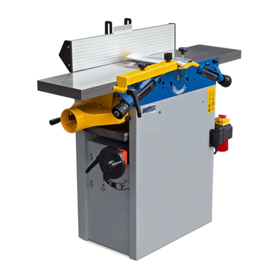
- Page 1 · COMBINED 10”& 12” PLANER & THICKNESSER Model No. ML392 ML393 ML393Q INSTRUCTION MANUAL Carefully read this instruction manual before operating machine.
-
Page 2: Table Of Contents
INDEX OF CONTENTS TABLE OF CONTENTS PAGE 1 GERNERAL SAFETY RULES PAGE 1-3 RECOMMENDATIONS PAGE 3 RECEPTION HANDLING PAGE 3-4 TRANSPORT AND STOCKING PAGE 4 PLACING THE MACHINE ON THE FLOOR PAGE 4 INSTALLATIONG PAGE 4 PREPERATION OF THE MACHINE PAGE 5 WORKING CONTITIONS PAGE 5... - Page 3 10. Connect dust extraction equipment. If devices are provided for the connection of dust extraction and collection equipment, ensure these are connected and properly used. 11. Do not abuse the cable. Never pull the power cable to disconnect it from the socket. Keep the cable from the socket.
-
Page 4: Recommendations
RECOMMENDATIONS No one must work on a wood machine without first receiving sufficient training concerning the type of work and without being informed of the risks, the precautions to observe and operating instructions for the guards and compulsory safety devices. This machine is designed for wood derivatives. -
Page 5: Transport And Stocking
TRANSPORT AND STOCKING During the transport and stocking it is necessary to protect the machine from excessive vibrations and excessive humidity. The machine can be stocked under the roof with air temperature from –25 C to 55 PLACING THE MACHINE ON THE FLOOR Remove the metal sheet clamping. -
Page 6: Preperation Of The Machine
PREPARATION OF THE MACHINE The machine unpainted parts are protected with a factory-applied ultra-fine oily film. It is not necessary to remove it before using the machine. However, if you wish you can remove it, use a cloth soaked spirit. Wipe and clean and then apply a sliding agent (Sliber-gleit, Molycote, etc.). WORKING CONDITIONS The machine is intended for work under the roof if the following conditions are fulfilled. -
Page 7: General Information
a standard 16A three pole + earth plug. Three wires are provided for the supply (L1, L2, L3) and the fourth (yellow/green) must be connected to the earth terminal. IMPORTANT: Three phase connection necessaries checking the correct direction of rotation of the motor shaft to avoid any problems with the belt drives. -
Page 8: Technical Data
TECHNICAL DATA Model No. 10”(ML392) 12”(ML393Q) 12”(ML393) Planer tables 1085x250mm 1285x310mm 1600x310mm Thicknesser tables 600x248mm 600x310mm 750x310mm Cutterblock diameter 75mm 75mm 95mm Cutterblock speed 4000rpm 4000rpm 4000rpm Fence tilt 0-45 0-45 0-45 Dust chute 100mm 100mm 100mm Number of knives... -
Page 9: Exhausting System
of 20m/s of the thicknessing station and a dust extraction air velocity of 10 m/s instead of 20 m/s, the noise level will be reduced by about 9 dB(A). An equivalent continuous sound level of 85 dB(A) is considered to be a danger threshold for a full-time daily exposure of 8 hours. -
Page 10: Working Operations
WORKING OPERATIONS Planing of narrow workpieces When planing narrow pieces, set the cover of the cutterblock in such a position so that the distance between the workpiece and the cutterblock cover is max 5mm. Then switch on the machine and push the material against the cutterblock (between the cutterblock cover and the rule). - Page 11 Planing of short workpieces Use the special holder when planing short workpiece. The possible execution you can see on the picture. Planing of workpieces with small cross section WARNING! There exisits danger of injury when leading the workpiece along the rule incorrectly. Use a wooden angle rule made by yourself.
-
Page 12: Adjustment Of Thicknesser
ADJUSTMENT OF THICKNESSER These are carried out in the factory, proceed with care, as they require a high level of competence. Thicknessing First adjust the Planer/Thicknesser t the function of thicknessing as follows. Swing away the safety protection. Move the rule to the utmost position off the planing table. Release the planing tables and swing away. -
Page 13: Tools
Safety instruments When working with circular saw, spindle moulder, planer and thicknesser, the operator must wear short strengthened apron and safety goggles. It is suitable to use adequate protection of hearing and recommended working footwear. It is forbidden to use working mantle. Workers qualification Only authorized worker specialized in woodworking branches (or worker instructed by this specialist) is allowed to work with the machine. -
Page 14: Maintenance
Clean the new knife carefully. Insert the new knife by screwing five screws (4) so that its extension above the surface of cutterblock in max 1.1mm. The manufacturer recommends the height of extension from 0.7 to 0.8mm. Then tighten the pressing off wedge with five screws. After all the above-mentioned steps are finished make sure to check whether all the five screws are in proper place and fix all protective covers and then try to start the machine by pushing the switch “ON”... -
Page 15: Repairs
The necessary clearance between the stock and he quill ( cylindrical rack system) is obtained by machining to ensure good overall rigidity and smooth handling. Parallelism between the table work surface and the cutterblock shaft is factory-set. REPAIRS Any defect should not arise if you are operating the machine in the right way and making the suitable maintenance regularly. -
Page 16: Parts Diagram
10”(ML392) &12”(ML393Q) PARTS DIAGRAM 15... - Page 17 16...
- Page 18 17...
- Page 19 Optional attachment 18...
-
Page 20: Parts List
10”(ML392 )&12”(ML393Q)PART LIST SPECIFICATION SPECIFICATION Base stand Locking plate Small cover plate Change-over plate Nut M6X12 Right cover plate Support sleeve Thicknessing table assembly Support base Lifting tube Right cutter block support Oriented body Left cutter block support splint Front adjusting block... - Page 21 SPECIFICATION SPECIFICATION Chain wheel I Bottom plate Chain wheel II Locking block Cast iron friction wheel Chain wheel III Tension plate Spring washer 20 Spring Big washer 10 Guiding fence Spring washer 6 Cutter block protective fence Nut M10 Fence plate Flat cap screw M5X6 Supporting plate HP screw M5X8...
- Page 22 SPECIFICATION SPECIFICATION Socket hex cap screw M8X16 Self-setting screw ST5X40 Socket hex cap screw M8X30 Nut M8 Screw M8X8 Nut M5 Screw M6X10 Hex cap bolt M8X16 Socket hex cap bolt M6X35 Socket hex cap screw M6X12 PH screw M4X6 PH screw M5x8 PH screw M4X6 Washer 5...
- Page 23 SPECIFICATION SPECIFICATION column External ring 10 Handle bar Big washer 10 Handle Helical wheel Eccentric wheel Spring pin 4X25 Shaft Thrust ball bearing 51102 Clamping body Bush mandril Rack ring Spring Screw M8X10 Elastic pin 4X20 Socket hex cap screw M6x12 Press block Big washer 6 Self –...
- Page 24 12”(ML393) PARTS DIAGRAM 23...
- Page 25 24...
- Page 26 25...
- Page 27 4 Optional attachment 26...
- Page 28 12”(ML393) PART LIST SPECIFICATION SPECIFICATION Base stand Blade 310x30x3 Motor base Compression spring Small cover plate Dust chute Right cover plate Dust chute head Support sleeve Locking plate Fixed plate Change-over plate Axle Nut M6X12 Screw Thicknesser table assembly Bush Lifting tube Adjusting screw Oriented body...
- Page 29 SPECIFICATION SPECIFICATION Spring Handle Spring Handle wheel Connecting plate Upper plate Chain wheel I Bottom plate Chain wheel II Cast iron friction wheel Pin 3.2x30 Socket hex cap screw Chain wheel III M10X16 Tension plate Dustproof cover (big) Spring Dustproof cover(small) Guiding fence Spring washer 6 Cutter block protective fence...
- Page 30 SPECIFICATION SPECIFICATION Hex cap screw M6X10 Z-VELT(L-1500) Nut M6 Washer 10 Support rubber cylinder Socket hex cap screw M6X12 Support rubber cylinder Socket hex cap screw M5X50 Self-setting screw ST5X40 Socket hex cap screw M10X16 Nut M8 Socket hex cap screw M8X35 Nut M5 Screw M10X8 Screw M8X16...
- Page 31 Part Name Q’ty Part Name Q’ty Column Spring washer 6 Hand pole Gear shaft Sheath Grank assemble “C” ring 10 Eccentricity ring Washer 10 Clamp base Gear shaft Balling rod Pin 4X25 Spring Bearing 51102 Pin 4X20 Bush Press block Fixed ring Pin 4X30 Set screw M8X10...
- Page 32 31...
Need help?
Do you have a question about the ML392 and is the answer not in the manual?
Questions and answers