Table of Contents

Related Manuals for NATURA NWSBU2 SER.4

Summary of Contents for NATURA NWSBU2 SER.4
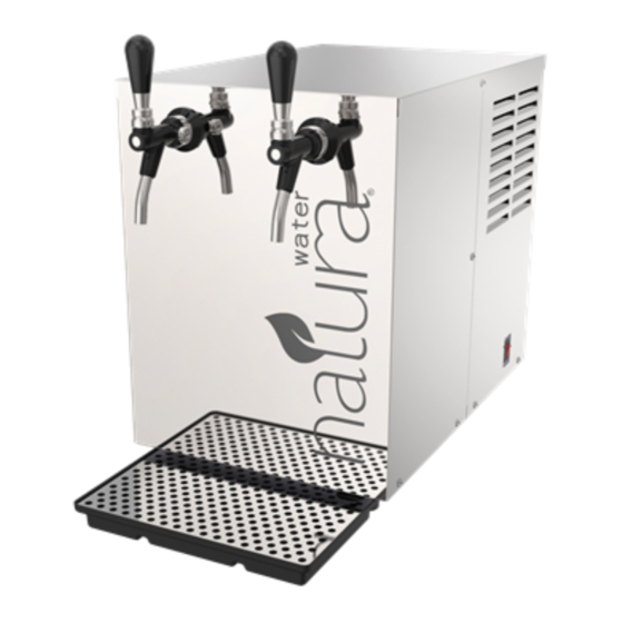
- Page 1 INSTALLATION AND MAINTENANCE GUIDE FOR: NATURA NATURA MODEL NWSB SER.4 MODEL NWSBU2 SER.4 COUNTERTOP WATER DISPENSER REMOTE CHILLER (Aquarius Series) (Aquarius Series) NATURA Water LLC. 222 East Campus View Blvd Columbus, Ohio 43235 U.S.A.
-
Page 2: Table Of Contents
18. WATER LEAK PROTECTION DEVICE ADJUSTMENT 19. START UP PROCEDURE 20. DRIP TRAY PLACEMENT 21. FILTER REPLACEMENT 22. MAINTENANCE 23. SPARE PARTS DRAWING - MODEL NWSB SER.4 24. SPARE PARTS DRAWING - MODEL NWSBU2 SER.4 25. TROUBLESHOOTING 26. CONTACT INFORMATION Installation and Maintenance Manual... -
Page 3: Product Specifications
1. PRODUCT SPECIFICATIONS: Dimensions: Length 19.0” Length with Drip Tray 24.5” Width 12.5” Height 17.9” Height with Taps 19.9” Weight - Empty 65 lbs Weight - with Water 100 lbs Refrigerant: 3.2 ounces, R-134a Input Voltage: 115 VAC, 60 HZ, SINGLE PHASE Amperage: 2.6 AMPS FLA Minimum Ambient Temperature:... -
Page 4: Important Requirements
2. IMPORTANT REQUIREMENTS: Use only original and new parts to guarantee the reliability, optimization, and performance of the Natura water machine. Always wear proper protection when performing any type of service or maintenance. Do not expose the CO Cylinder to direct sun light, to sources of heat, or to temperature below 32°... -
Page 5: Directions For Proper Placement Of The Components
4. DIRECTIONS FOR PROPER PLACEMENT OF THE COMPONENTS: Place the unit in an appropriate location, far from heat sources and with adequate ventilation, on a fl at level surface. The surface must be able to support the 100 lb weight of the unit. Locate the unit within 10 feet of a water supply. -
Page 6: Proper Quick Connect Fitting Connection Instructions
5. PROPER QUICK CONNECT FITTING CONNECTION INSTRUCTIONS: Connections between the Pressure Regulator, Filtration Unit and Water Refrigeration Unit are accomplished using plastic tubing and push-together quick-connect type fi ttings. PLASTIC TUBING QUICK-CONNECT FITTINGS Cut tube ends square and straight. Fittings consist of two parts: a body and Do not deform the tube (i.e., cause a colored collet. -
Page 7: Counter Top Model Schematic
6. COUNTER TOP MODEL SCHEMATIC: WATER INLET/FILTRATION SYSTEM CUSTOMER SUPPLIED VALVE NOTE: WATER LEAK PROTECTION DEVICE MUST BE INSTALLED. (IN VERTICAL POSITION) NOTE: NOTE: GROUND FAULT CIRCUIT CYLINDER INTERRUPTER (GFCI) SUPPLIED BY OUTLET RECOMMENDED. CUSTOMER ( 10-15-20 LBS) REFRIGERATION/CARBONATION SYSTEM SUPPLY SYSTEM Installation and Maintenance Manual... -
Page 8: Water Inlet/Filtration Installation
7. WATER INLET/FILTRATION INSTALLATION: NOTE: WATER LEAK PROTECTION DEVICE MUST BE INSTALLED PROPERLY IN VERTICAL POSITION PER INSTRUCTIONS PROVIDED. STEP 1 CUSTOMER 3/8” ELBOW SUPPLIED STEP 2 VALVE BRAIDED HOSE CARBON NANO ADAPTER WALL MOUNT FITTING BRACKET STEP 3 WATER LEAK PROTECTION FILTER SET WATER... - Page 9 8. WATER INLET/FILTRATION INSTALLATION: STEP 1 3/8” COMPRESSION FITTING CUSTOMER SUPPLIED VALVE BRAIDED HOSE ADAPTER FITTING NOTE: WATER LEAK PROTECTION DEVICE IS FACTORY SET AT 2. WATER LEAK PROTECTION DEVICE NOTE: (WATER BLOCK) WATER LEAK PROTECTION DEVICE MUST BE ASSEMBLED AND ADJUSTED PER THE DETAILS IN SECTION 18.
- Page 10 9. WATER INLET/FILTRATION INSTALLATION / FILTER INSTALLATION: STEP 2 INLET OUTLET FILTER BRACKET 3/8” ELBOW 3/8” ELBOW NOTE: FILTER MANIFOLD ON TOP OF THE PLASTIC FILTER MANIFOLD THE INLET & OUTLET PORTS ARE MARKED. FOR PROPER OPERATION THIS CONFIGURATION IS REQUIRED. FILTER SET Pre-Sediment Filter (Inlet Side) Carbon Filter...
- Page 11 10. WATER INLET/FILTRATION INSTALLATION: STEP 3 3/8” O.D. TUBING NOTE: WATER LOOK FOR FLOW DIRECTION ON PRESSURE WATER PRESSURE REGULATOR. REGULATOR ADAPTER FITTINGS WATER SHUT-OFF VALVE Connect the components in order as shown above. Connect 3/8” O.D. tube from Water Pressure Regulator exit port to the 3/8” elbow inlet port on the Filter Set.
-
Page 12: Co Supply System Installation
12. CO SUPPLY SYSTEM INSTALLATION: NOTE: SEAL / O’RING THE CO LINE SHOULD NOT BE PRESSURIZED AT THIS TIME. CYLINDER VALVE PRESSURE REGULATOR CYLINDER 1/4” O.D. TUBING NOTE: DO NOT CONNECT CO TUBING TO THE UNIT UNTIL THE INSTALLATION IS COMPLETE. (SECTION 13 FOR COUNTER TOP UNIT) (SECTIONS 15 &... -
Page 13: Counter Top Model Installation
13. COUNTER TOP MODEL INSTALLATION: FLOW ADJUSTMENT LEVER STILL WATER TAP CARBONATED WATER TAP FIXED FLOW VALVE WITH FLOW ADJUSTMENT NOTE: DO NOT OPEN VALVE TO CO CYLINDER UNTIL START-UP PROCEDURE FOUND IN SECTION 19. FROM FROM FILTER SET CYLINDER Connect the 3/8”... -
Page 14: Counter Top Model Tap Installation
14. COUNTER TOP MODEL TAP INSTALLATION: TURN CHROME RING COUNTER VERTICALLY ALIGNED CLOCKWISE TO TIGHTEN FRONT PANEL FITTING FLOW ADJUSTMENT (ADJUST TO 1 LITER/15 SEC) TAP BODY (CARBONATED WATER TAP) Locate the two Taps. They are in the top pad of the packaging. Starting on the left, install the Carbonated Water Tap with Flow Adjustment. -
Page 15: Remote Chiller Model Shank Assembly
15. REMOTE CHILLER MODEL SHANK ASSEMBLY: WATER DISPENSE SYSTEM STILL WATER SUPPLY CARBONATED WATER SUPPLY SHANK SHANK WASHER SHANK FITTING SHANK ADAPTER NUT LOCKING CLIP 3/8” X 5/16” REDUCING ELBOW Assemble the Shank Washer, Shank Fitting, Shank Adapter Nut, Locking Clip, and Reducing Elbow as show in the illustration above. -
Page 16: Remote Chiller Model Installation
16. REMOTE CHILLER MODEL INSTALLATION: CARBONATED WATER CARBONATED STILL WATER WATER TAP STILL WATER TAP REMOTE CHILLER DISPENSE TOWER MODEL FROM FILTER SET FROM CO CYLINDER 5/16” O.D. TUBING 5/16” UNION FITTING 1/4” X 5/16” REDUCING FITTING OR NOTE: 5/16” UNION FITTING FLOW COMPENSATOR MUST BE ADJUSTED PER INSTRUCTIONS... - Page 17 Remote Chiller Model Installation- Connection of the Still Water Tubing. Insert the 5/16” O.D. tubing into the tubing insulation provided. Connect the 5/16” O.D. tubing to the right elbow quick connect fi tting on the front of the unit. Connect the other end of the tubing to the 5/16” Union Fitting on the right side of the Dispense Tower.
-
Page 18: Flow Compensator Adjustment
17. FLOW COMPENSATOR ADJUSTMENT ( FOR REMOTE CHILLER MODEL ONLY ) WATER INLET FROM REMOTE CHILLER water fl ow has been factory-set to provide the proper fl ow rate of approximately 1liter/15 sec. However, it may be necessary to adjust this in the fi... - Page 19 The Water Leak Protection Device is an overfl ow safety device that controls the maximum consumption of water between 5 and 50 liters. Its function is to measure the volume of water that passes through it. If this volume exceeds the set value, the Water Leak Protection Device stops the fl...
-
Page 20: Start Up Procedure
19. STARTUP PROCEDURE: Remove the two lid screws and the Lid to access the inside of the unit. Make sure that all of the water and connections have been made. Open the Water Shut Off Valve and check the system for leaks. Open the Pressure Relief Valve located on the carbonator tank by pushing down on the Pressure Relief Ring as shown below. - Page 21 Fill the Insulated Reservoir with distilled or de-ionized water. Have 5 Gallons available. Fill to the level shown. Carefully fi ll until the water level is just below the Condensation Overfl ow Outlet. FILL TO THIS LEVEL COUNTER TOP MODEL WATER LEVEL TOUCHING BUT NOT EVAPORATOR OVERFLOWING INTO CONDENSATION...
-
Page 22: Drip Tray Placement
OUTLET HOLE DRIP TRAY The Drip Tray supplied with your Natura product is designed to collect condensation that accumulates during normal operation of the unit. The Condensation Outlet is located on the bottom of the machine about 1 inch from the front right corner. -
Page 23: Filter Replacement
21. FILTER REPLACEMENT: The Filters should be replaced every 6 months or before 10,000 gallons of water usage. Turn off the main water supply and disconnect the power from the unit. Open the Still Water Faucet (right side faucet) to release water pressure from the line. Unscrew the Filter Housing counter clockwise to remove it to access the Filter. -
Page 24: Maintenance
22. MAINTENANCE: Unplug the electric power connection, and shut off the water supply and supply during maintenance or malfunction of the unit. The faucets and nozzles of the counter top unit should be wiped off on a daily basis with a clean cotton rag or non-abrasive sponge and hot water. The Drip Tray should be emptied and cleaned with hot water on a daily basis. - Page 25 23. SPARE PARTS DRAWING - MODEL NWSB SER.4 Model NWSB SER.4 ITEM PART NO. DESCRIPTION ITEM PART NO. DESCRIPTION 029191-004 FUSE, 1.25A 036544-102 WATER PUMP 034949P999 PRESSURE RELIEF VALVE 038324-001 FRONT PANEL 035545-004 CONDENSER FAN 038327-001 036247-016 PLASTIC LID 038343-002 ICE BANK CONTROL 036287-013 DRIP TRAY GRILL...
- Page 26 24. SPARE PARTS DRAWING - MODEL NWSBU2 SER.4 Model NWSBU2 SER.4 ITEM PART NO. DESCRIPTION ITEM PART NO. DESCRIPTION 029191-004 FUSE, 1.25A 038327-004 034949P999 PRESSURE RELIEF VALVE 038343-002 ICE BANK CONTROL 035545-004 CONDENSER FAN 038359-003 WATER COIL 036247-016 PLASTIC LID...
-
Page 27: Troubleshooting
25. TROUBLESHOOTING: PROBLEM POSSIBLE CAUSE SUGGESTION Unit not working. - No power. - Check the power outlet, plug connection, and the circuit breaker. Power switch is “ON”. The refrigeration system is - The agitator motor has failed. - Replace agitator. working but the agitator has stopped. - Page 28 PROBLEM POSSIBLE CAUSE SUGGESTION The water has an unusual - Filters clogged. - Replace Filters. taste. used was not for - Check the type of (UN 1013). If necessary, drinking water. change the tank. - Incoming water quality - Clean & Sanitize the faucets. Water is not suffi...
-
Page 29: Contact Information
For technical support, contact the Technical Service Department, Distributor or Vendor of the unit. Or you may contact: NATURA Water LLC. 222 East Campus View Blvd Columbus, Ohio 43235 1-877-302-8638 www.naturawater.com 036333-013 REV. C Natura is a registered trademark of Natura, Inc. © 2017 Natura, Inc.
Need help?
Do you have a question about the NWSBU2 SER.4 and is the answer not in the manual?
Questions and answers