Advertisement
Quick Links
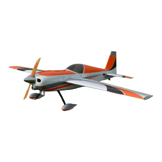
30cc Slick 540
Thank you for purchasing a Redwing RC aircraft. We have
worked hard to provide you with a high quality and great flying
aircraft. Please read through the manual before starting the
assembly. If you have any questions about your aircraft you can
E-mail us
info@redwingrc.com
or call us at 636-600-8735.
Thank you
Redwing RC
Advertisement

Summary of Contents for RedWing RC 30cc Slick 540
- Page 1 30cc Slick 540 Thank you for purchasing a Redwing RC aircraft. We have worked hard to provide you with a high quality and great flying aircraft. Please read through the manual before starting the assembly. If you have any questions about your aircraft you can E-mail us info@redwingrc.com...
-
Page 2: Specifications
Redwing RC assumes no liability for any damage resulting from the user assembled product. By the act of using the assembled product, the user accepts all resulting liability. The purchaser or designated person flying this aircraft accepts all liability associated with the use of this product. -
Page 3: Additional Items Needed
Miscellaneous Needed: Drill and Drill Bits Rotary Tool & Sanding Drum Various Hand tools Thread locker Hobby Knife Crimping tool 30-Minute Epoxy Additional Items Needed: 30cc to 36cc single cylinder engine Factory Muffler or Canister Muffler Propeller (Engine manufacturer recommended) 3 ½”... - Page 4 Carefully remove the aircraft from the boxes and inspect for any damage. If you have any damage it must be reported to the freight company immediately. Redwing RC is not responsible for any shipping damage. You must contact the carrier. We will work with the purchaser and the freight company to resolve any issues.
-
Page 5: Getting Started
climates, the covering may become lose and wrinkle in the sun. If you take the time to re-tighten the covering, you will be rewarded with a long lasting and beautiful airplane. Using your covering iron with a soft sock, gently apply pressure and rub in the covering. If any bubbles occur, your iron may be to hot. - Page 9 Control Horn Installation: (Elevator Hardware Bag) (Rudder Hardware Bag)
- Page 10 (Wing Hardware Bag) The control horns come pre-assembled and pre-painted. Use 30 minute epoxy to glue the control horns in place. (Elevator Control Horn)
- Page 11 (Elevator Control Horn Installed) The rudder control horns need 1/8” trimmed off of the bottom of each control horn so they don’t hit inside the rudder. (Rudder Control Horn Trimmed)
-
Page 12: Landing Gear Installation
Landing Gear Installation: (Landing Gear Hardware Pack) Install the axles on the Carbon Fiber Landing gear as shown. - Page 13 (Landing Gear Mounting Hardware) (Landing Gear Cover) Place the flat washers on each of the four socket head cap screws. These screws go through the holes in the landing gear cover and then through the holes in the landing gear. The landing gear is then secured in place by installing the four locknuts in the fuselage.
- Page 14 (Landing Gear Installed) (Lock Nuts installed inside fuse)
- Page 15 Tail wheel Bracket Installation: (Tail Wheel Assembly)
- Page 16 Assemble the tail wheel bracket as shown. Install the tail wheel assembly on the fuselage. Make sure the bracket is centered on the bottom of the fuselage.
- Page 17 Hinging the Control Surfaces: 30 minute epoxy is used to glue the hinges in place in the control surfaces. Be careful to not get any epoxy in the hinge joint. Once the epoxy has fully cured the control surfaces can be glued in place on the airframe.
- Page 18 Before gluing the rudder in place on the fuselage install the tail wheel tiller arm mount in the rudder. Drill a 3/16” hole located 2 ½” from the hinge line. The mount is centered on the rudder. Glue the mount in place with 5 minute epoxy.
- Page 19 (Rudder Installed) Aileron Servo Installation:...
- Page 20 (Aileron Servo Mount) Attach a 6”-12” servo extension to each aileron servo. Place a servo safety clip over the connectors. Use servo screws to mount the servo in the servo mount. Install your preferred servo arms on the aileron servo. Included with the aircraft are carbon fiber servo arms that bolt on to your existing servo arms.
- Page 21 choose aluminum servo arms. Make sure to apply medium thread locker to the servo screw. (Included Servo Arms) (Aileron Servo Installed)
- Page 22 Connect the pushrods as shown. The pushrods are right hand thread on one end and reverse threaded on the other. This allows for easy pushrod length adjustment.
- Page 23 Elevator Servo Installation: Attach a 24” servo extension to each elevator servo. Place a servo safety clip over the connectors. Route the servo extension through the fuselage to the equipment tray. Use servo screws to mount the servo in the servo mount. The servos output shaft faces the rear of the aircraft.
- Page 24 Rudder Servo Installation: Install the rudder servo in the fuselage. The servos output shaft faces toward the front of the aircraft. Use servo screws to secure the servo in the servo mount. Install a 3”-4” double servo arm on the rudder servo. Make sure to apply medium thread locker to the servo screw.
- Page 25 Rudder Pull-Pull Cable Installation: Run the pull-pull cables through the fuselage, the cables exit at the rear of the fuselage. The cables cross inside the fuselage Rudder Pull-Pull Cable Assembly:...
- Page 26 Assemble the pull-pull cables as shown. Use a crimping tool to secure the cables.
- Page 28 The cables should not have any slack in them. They should be tight, but not guitar string tight. Re-check the cables after the first few flights, they may stretch slightly and need adjusting. Horizontal Stab Installation: The horizontal stabilizers slide onto the carbon fiber tail tube, two socket head cap screws, rubber washers, and flat washers secure them in place.
- Page 31 Elevator Pushrod Installation: Connect the pushrods as shown. The pushrods are right hand thread on one end and reverse threaded on the other. This allows for easy pushrod length adjustment. Apply medium thread locker to the servo screw.
-
Page 32: Engine Installation
Engine Installation: The firewall is pre-marked for a DLE-30. If using a different engine; tape or clamp the engine mounting template in place on the firewall and drill the four holes for your engine. - Page 33 The spacing from the firewall to the front of the cowling is 6 3/8”. We spaced our engine out to 6 1/2” to provide for a nice cowling to spinner fit. Select standoffs that provide the necessary spacing for your engine. Flat washers can be used between the standoffs and firewall to make slight adjustments.
- Page 35 Throttle Servo Installation: (Throttle Servo Mount)
- Page 36 Use 30-minute epoxy to glue the servo mount in place. After the epoxy has fully cured; attach the throttle servo pushrod to the engines carburetor.
- Page 37 Attach a 12” servo extension to the throttle servo. Ignition Unit Installation: The ignition unit mounts in the motor box. Drill a hole in the bottom of the engine box to allow an exit for the spark plug wire. A rubber grommet can be used to protect the spark plug wire from chaffing.
- Page 39 Install the motor box cover as shown.
-
Page 40: Cowling Installation
Cowling Installation: Use cardboard or card stock to make a template for the needle valve adjustment openings. Once the template is made; install the cowling, and then use the template to mark the opening on the cowl. Remove the cowl and use a drill to make the needle valve adjustment opening. - Page 41 The cowling is large enough to allow the DLE-35RA muffler to fit inside the cowl with only the down pipes exiting the bottom of the cowling. Use cardboard or card stock to make a template for the muffler openings. Once the template is made; remove the mufflers from the engine, install the cowling, and then use the template to mark the openings on the cowl.
- Page 42 tool with a sanding drum to make the openings for the muffler exits.
- Page 43 If a quieter exhaust system is needed: the Slick is equipped with an exhaust tunnel in the fuselage that will allow mounting of a canister muffler. The cowling features a built in cowl ring. The cowling is secured to the fuselage by four screws: two screws inside the fuselage, and two screws from inside the cowling.
- Page 44 installation. Remove the covering over the fuel dot location and install the fuel dot as shown.
- Page 45 There is plenty of room in the Slick for up to a 16 ounce fuel tank. A fuel tank is included with the Slick. Redwing RC also has Fortitude RC fuel tanks available. Follow the fuel tank manufactures instructions for assembling the fuel tank.
- Page 47 Place foam rubber under the battery and receiver to protect them from shock and vibration. Use hook and loop material to secure the batteries and receiver. Wheel and Wheel Pant Installation: Install the wheels and wheel pants as shown, use medium thread locker on the wheel pant bolts.
-
Page 50: Wing Attachment
Wing Attachment: The wings slide onto the carbon fiber wing tube, a nylon wing bolt secures each wing panel in place. -
Page 51: Canopy Attachment
Canopy Attachment: The canopy comes ready to mount. Two socket head cap screws, rubber washers, and flat washers are used to secure the canopy assembly. - Page 52 Balancing: Assemble the airplane ready to fly (minus fuel.) For the initial flights balance the aircraft on the wing tube. Mark the locations at the wing tip and have a friend help you lift the aircraft by the wing tips at this location. The aircraft should balance level or slightly nose down.
- Page 53 AILERON: Low Rate: 25 degrees each direction – 25% Expo High Rate: 40 degrees each direction – 40% Expo RUDDER: Low: 30 degrees each direction – 20% Expo High: 50 degrees each direction – 35% Expo Pre-flight: The engine should be properly adjusted and running smoothly. It should have a good throttle transition and a reliable idle.
- Page 54 Make sure that you have used thread locker on all nuts and bolts. We recommend using low rates for the initial test flights. Enjoy your Redwing RC aircraft, have fun, and fly safe. Remember to always follow the Academy of...
Need help?
Do you have a question about the 30cc Slick 540 and is the answer not in the manual?
Questions and answers