Table of Contents
Advertisement
Technical documentation
NAVIGATION LIGHT CONTROL
For use on seagoing vessels
Change status
Version
Date
0.1
07.08.2008
0.2
29.09.2010
0.3
08.04.2016
0.4
12.01.2017
Tel: +49 (0)4105/65 60 – 0
E-mail:
- NLS 3000 -
Author
Checked
STO
HN
STO
TK
TK
TK
TK
TK
* DECKMA GmbH *
info@deckma-gmbh.de
Page 1 of 27
OPERATING MANUAL
NLS 3000 NAVIGATION
LIGHT CONTROL PANEL
Remark
1. Edition
Changes to BK01-E to
BK08...48-E
Some small errors corrected
„Special function" handmade (p. 21)
Fax: +49 (0)4105/65 60 – 25
*
Internet:
www.deckma-gmbh.de
Advertisement
Table of Contents

Summary of Contents for Deckma Hamburg NLS 3000
- Page 1 OPERATING MANUAL NLS 3000 NAVIGATION LIGHT CONTROL PANEL Technical documentation - NLS 3000 - NAVIGATION LIGHT CONTROL For use on seagoing vessels Change status Version Date Author Checked Remark 07.08.2008 1. Edition 29.09.2010 Changes to BK01-E to BK08...48-E 08.04.2016 Some small errors corrected 12.01.2017...
-
Page 2: Table Of Contents
3.5 Graphic control panel 15-17 3.6 VM01-E VDR module 3.7 SM01-E interface module 3.8 DT01-E data module 4.0 Operation of NLS 3000 via conventional BK08...48-E 21-22 5.0 Operation of NLS 3000 via graphic BG01-E 23-24 6.0 Mechanical specification 6.1 BK01-E conventional control panel 6.2 BG01-E graphic control panel... -
Page 3: Application And Design
The NLS 3000 navigation light control panel is in a modular design. The light modules (light switching and monitoring) are installed in a control cabinet together with the main module (power and master module monitoring). -
Page 4: Modules
Use for service purposes or configuration updates 2.9 FMS 3000 RS232 terminal adapter • Interface for connection of the data module interface 8 (on NLS 3000 / MM01-E) with PC (RS232) • Use for service purposes only (see and respect the separate service manual for this!) * DECKMA GmbH * Tel: +49 (0)4105/65 60 –... -
Page 5: Description Of The Modules
0.5 kg 3.1.1 General The main module is the communication master within the NLS 3000 communication system. In addition to the power for the connected modules, the main module includes a power monitoring circuit. The main module also has a connection for an optional data module DT01-E. - Page 6 OPERATING MANUAL NLS 3000 NAVIGATION LIGHT CONTROL PANEL 3.1.2 Optional display For easy system analysis and display of nominal and actual values, a display board can be added. The display is controlled by a microcontroller via an 8-bit databus and RS, RW and E (clock). The buttons on the display board are read-in directly via microcontroller ports.
- Page 7 0.4 A 3.2.1 General The "8-circuit lantern module" is a communication slave within the NLS 3000 communication system. It allows the connection of up to 8 lights/lanterns which can be switched on or off via relays with a conventional “2-pole” glass fuse protection (5x20mm).
- Page 8 OPERATING MANUAL NLS 3000 NAVIGATION LIGHT CONTROL PANEL 3.2.3 LEDs and DIP switch functions (microcontroller board) "EXT" ⇒ External communication: (2 LEDs) • Communication status with master via NLS bus system • Green flashing ⇒ Communication without faults • Red short ⇒...
- Page 9 OPERATING MANUAL NLS 3000 NAVIGATION LIGHT CONTROL PANEL How to readout and reset the operating hours counter (used for an 8 channel module) HOUR-LED (amber): Operating hours display active OK-LED (green): Display of the chosen channel FAULT-LED (rot): Display the operating hours Push the button “LED HOUR”.
-
Page 10: Lm02-E 2-Channel Lantern Module
OPERATING MANUAL NLS 3000 NAVIGATION LIGHT CONTROL PANEL 3.3 NLS 3000 LM02-E 2-channel lantern module Width 124mm Height 108 mm Depth 50 mm + connector around 80mm Mounting method Top-hat rail DIN EN 50022 Weight 0.8 kg Supply 24V DC... - Page 11 OPERATING MANUAL NLS 3000 NAVIGATION LIGHT CONTROL PANEL 3.3.3 LEDs and DIP switch functions (microcontroller board) "EXT" ⇒ External communication: (2 LEDs) • Communication status with master via NLS bus system • Green flashing ⇒ Communication without faults • Red short ⇒...
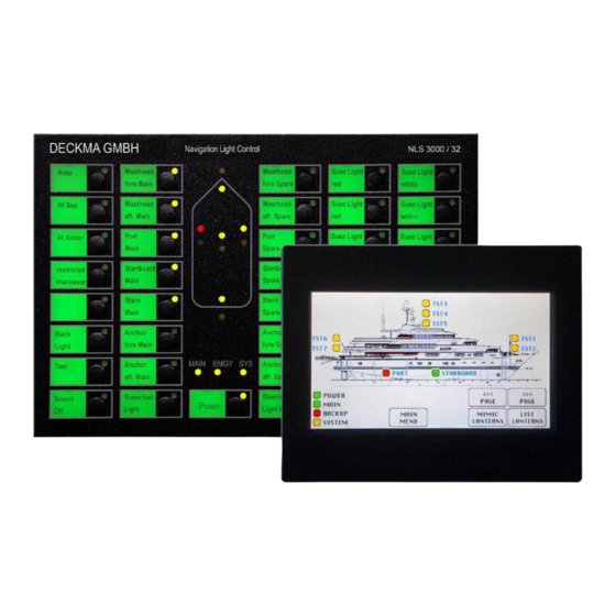
- Page 12 3.4.3 General buttons For general control of the NLS 3000, permanent and configurable functions are implemented. The associated buttons are arranged in the left section of the control panel or directly below of the ship’s mimic indication.
- Page 13 OPERATING MANUAL NLS 3000 NAVIGATION LIGHT CONTROL PANEL 3.4.5 Power and system: Emergency LED System status LED Main LED Power status LED Labelling field Power status button Labelling field • Marking with button function: …here: "Power" Power status button •...
- Page 14 OPERATING MANUAL NLS 3000 NAVIGATION LIGHT CONTROL PANEL 3.4.6 Function and light buttons: Status LED Labelling field Status button Labelling field • Marking with associated button function Status button • Switches associated function or light on or off Status LED •...
-
Page 15: Graphic Control Panel
16 it (65,536) 3.5.1 General The "graphic control panel" is a communication slave within the NLS 3000 communication system. It serves for display and control of the NLS, enabling lights to be switched on or off. From this control panel, the NLS generates visual and audible alarms on faults in the light circuits or in the NLS and system power supply. - Page 16 OPERATING MANUAL NLS 3000 NAVIGATION LIGHT CONTROL PANEL 3.5.2 Power and system: Power status LED Main LED Power status button Emergency LED System status LED Labelling field • Marking with button function: …here: "Power" Power status button • Switches the power for the lights •...
- Page 17 OPERATING MANUAL NLS 3000 NAVIGATION LIGHT CONTROL PANEL 3.5.3 Function and light button: Status LED Status button Labelling field Labelling field • Marking with associated button function Button status • Switches associated function or light on or off Status LED •...
-
Page 18: Vm01-E Vdr Module
OPERATING MANUAL NLS 3000 NAVIGATION LIGHT CONTROL PANEL 3.6 NLS 3000 VM01-E VDR module Width 72 mm Height 104 mm Depth 88 mm Mounting method Top-hat rail DIN EN 50022 Weight 0.3 kg 3.6.1 General The VDR module sends data via RS485 or RS232 to a VDR (Voyage Data Recorder). The module can alternatively be provided with drivers for RS485 or RS232. -
Page 19: Sm01-E Interface Module
0.005 A Supplied from module 3.7.1 General The slave module serves for connection of the NLS 3000 main module to the ship automation system. It decouples both systems. 3.7.2 Connector Communication takes place via an RS232 driver module with the main module and via an RS485 module with the ship automation system. -
Page 20: Dt01-E Data Module
OPERATING MANUAL NLS 3000 NAVIGATION LIGHT CONTROL PANEL 3.8 FMS 3000 DT01-E Data module Width 54 mm Height 60 mm Depth 17 mm Mounting method Plug-in Weight 0.05 kg Data and power connection 25-pin DSub male Supply 5V DC Power consumption max. - Page 21 4.1 Switching on NLS 3000 and power supply switching Provided for switching the NLS 3000 on and off are control and indicating elements arranged directly below the ship mimic. Two green LEDs (labelled "MAIN" and "EMGY") indicate via a steady light the presence of the respective power supply.
- Page 22 OPERATING MANUAL NLS 3000 NAVIGATION LIGHT CONTROL PANEL The programming (or better “matching”) to one of these 4 possible buttons works as follows: 1) All lanterns, who should act later on to this button, must be switched on! 2) Now the button [SOUND OFF] must be pressed and MUST held down permanently! 3) Now press the button whom should act with this lantern set (button 1/2/3 or 4) 4) From now on this “special function”...
- Page 23 LED flashes red or shows a steady light. The NLS 3000 is switched on by pressing the "Power" button. The NLS 3000 can be switched off by pressing and holding the button for around 3 seconds. When the button is pressed during operation, switching takes place between the main and backup power supply.
- Page 24 OPERATING MANUAL NLS 3000 NAVIGATION LIGHT CONTROL PANEL For lights using LEDs, the operating time is also monitored. If the maximum permissible operating time is exceeded, a fault is generated. 5.6 Ship mimic For the main lights, display is provided in the form a ship mimic. When these lights are switched on, the associated LED in the ship mimic also lights up and flashes on faults.
-
Page 25: Mechanical Specification
OPERATING MANUAL NLS 3000 NAVIGATION LIGHT CONTROL PANEL 6.0 Mechanical specifications 6.1 Dimensions of conventional control panel BK 08...48- E 6.2 Dimensions of graphic control panel BG 01- E * DECKMA GmbH * Tel: +49 (0)4105/65 60 – 0 Fax: +49 (0)4105/65 60 – 25 E-mail: info@deckma-gmbh.de... -
Page 26: Control Cabinet For Up To 16 Light Circuits
OPERATING MANUAL NLS 3000 NAVIGATION LIGHT CONTROL PANEL 6.3 Dimensions of control cabinet for up to 16 light circuits 6.4 Dimensions of control cabinet for 17-48 light circuits * DECKMA GmbH * Tel: +49 (0)4105/65 60 – 0 Fax: +49 (0)4105/65 60 – 25 E-mail: info@deckma-gmbh.de... -
Page 27: Installation Instruction
OPERATING MANUAL NLS 3000 NAVIGATION LIGHT CONTROL PANEL 7.0 Installation instructions 7.1 Cable requirements The following cables are recommended for a safe and reliable operation for the complete system: Main and emergency power supply: unshielded cable min. 3x1.5mm ² Lights/lantern outputs: unshielded cable min.
Need help?
Do you have a question about the NLS 3000 and is the answer not in the manual?
Questions and answers