
Summary of Contents for PAVONE DAT 500
- Page 1 DAT 500 Digital Transmitter TECHNICAL MANUAL For Analog/Profibus/Devicenet versions Software version PW13081...
- Page 2 Page II...
-
Page 3: Table Of Contents
TABLE OF CONTENTS PRECAUTIONS ....................Page INTRODUCTION ................... Page TECHNICAL FEATURES ................... Page INSTALLATION ....................Page FRONT PANEL OF THE INSTRUMENT .............. Page 10 USING THE KEYBOARD ................. Page 11 INFO DISPLAY ....................Page 13 VIEWING, ZEROING THE WEIGHT AND SELF-CALIBRATION ......Page 14 SETTING ....................... -
Page 4: Precautions
PRECAUTIONS READ this manual BEFORE operating or servicing the instrument. FOLLOW these instructions carefully. SAVE this manual for future use. CAUTION The installation and maintenance of this instrument must be allowed to qualified personnel only. Be careful when you perform inspections, testing and adjustment with the instrument on. -
Page 5: Introduction
INTRODUCTION The DAT 500 is a transmitter of weight to be combined with the load cells to detect the weight in every situation. The display allows easy reading of the weight, the status of the instrument, the setting parameters and errors. -
Page 6: Technical Features
TECHNICAL FEATURES Power supply 24 Vdc ± 15 % Max. absorption Insulation Class II Installation category Cat. II Operating temperature -10°C ÷ +40°C (max. humidity 85% non-condensing) Storage temperature -20°C ÷ +50°C Weight display Numerical with 6 red led digits and 7 segments (h 14 4 LEDs of 3 mm Keyboard 4 mechanical keys... -
Page 7: Installation
INSTALLATION GENERAL DATA The DAT 500 is composed of a motherboard, on which you can add the options available; the mother- board is housed in a plastic enclosure. The DAT 500 should not be immersed in water, subjected to jets of water and cleaned or washed with solvents. - Page 8 20 to 21. Connect the cell cable shield to the terminal 2. In the case of the usage of two or more load cells, use special jun- ction boxes. Below please find their connection. J-BOX CGS4 DAT 500 +EXC +EXC -SGN SIGN-...
- Page 9 15 meters (EIA RS-232-C), beyond which you should take the optional RS485 interface. RS422/RS485: The serial port RS485 (2-wire) is present in the model DAT 500/ RS485. S.GND To achieve the serial connection, use a suitable shielded cable, ma-...
- Page 10 For a reliable operation of the Fieldbus, should be used a line ter- mination at both ends. In the case of multiple DAT 500 instruments, use the line termination at only one instrument. For configuring the instrument, the GSD file is available (hms_1810.
- Page 11 DEVICENET CONNECTION Signal Description Negative power bus CAN_L CAN low bus line SHIELD Shield CAN_H CAN high bus line Positive power bus CAN_L To connect to the DeviceNet master, use a standard DeviceNet cable CAN_H or shielded twisted-pair cable as shown on the diagram. The cable must not be channeled with power cables.
-
Page 12: Front Panel Of The Instrument
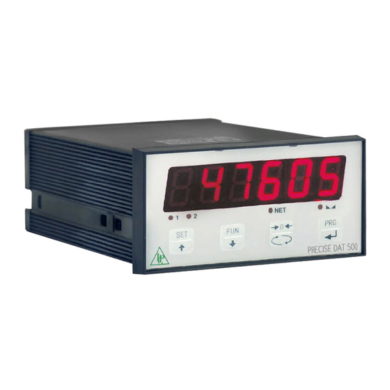
FRONT PANEL OF THE INSTRUMENT The DAT 500 has a bright 6-digit display, 4 status LEDs and four keys. In this operating mode the display shows the weight and the LEDs indicate the status of weight and the setpoints. The set-up parameters are easily accessed and modified through the use of the three front buttons used to select, edit, confirm and save the new settings. -
Page 13: Using The Keyboard
USING THE KEYBOARD The instrument is programmed and controlled through the keyboard which has 4 keys, with double functions. The selection of one of the key functions is established automatically by the instrument accor- ding to the operation in progress. In general, the management of the programming menus is done by using the SET and FUN keys to scroll through the items;... - Page 14 FUNCTION WHEN SETTING THE NUMERICAL VALUES It selects the next value. It selects the previous value. It confirms and store the displayed value. EXIT FROM THE SETTING MENU Press the key to return to the main menu. Press the . key again. It’s displayed “StORE?”. Press the key to return to the main menu.
-
Page 15: Info Display
INFO DISPLAY When the instrument is switched ON, you can test the display, then in sequence you can display the identification code of the software and its version. Communication codes in the event of a request for assistance. ERRORS NOTIFICATION In the operation mode, the display can report the following error codes. -
Page 16: Viewing, Zeroing The Weight And Self-Calibration
VIEWING, ZEROING THE WEIGHT AND SELF-CALIBRATION After being calibrated, at the subsequent switches on, the display shows the current weight. VIEWING THE NET WEIGHT/GROSS WEIGHT Press the key to toggle between the net weight and the gross weight and vice versa. The value displayed is signaled by the LED NET (lit: net weight). - Page 17 • Unstable weight (with control of the stability of the weight enabled). In this case, the reset command takes effect only if the weight stabilizes within 3 seconds or if the control of the weight stability is disabled (parameter “MOTION “ equal to zero). •...
- Page 18 PROGRAMMING THE WEIGHT SETPOINTS The set setpoint values are compared with the weight to drive its logic output. The comparison criterion is established in the process of set-up of the logic I / O (see relevant paragraph). To access the Setpoint setting, press the SET key and follow the instructions on the figure below. ...
- Page 19 KEYBOARD LOCK/UNLOCK FUNCTION KEYBOARD LOCK/UNLOCK A function that allows you to enable or disable the keys individually. When the keys are locked, the only way to access these settings is to press and hold pressed the PRG + 0 keys for 3 seconds. For more information on the function, refer to the block diagram above. SWITCHING THE DISPLAY OFF This function allows turning off the display after a programmable time.
-
Page 20: Setting
SETTING GENERAL DATA All functions of the DAT 500 are activated and modified by accessing a simple setup menu, shown afterwards. All settings selected or activated remain stored even after switching off the transmitter. The DAT 500 is preconfigured with a default setting. The following pages show the values of “Default”... - Page 21 FUNCTION WHEN SETTING THE PROSED VALUES It selects the next value. It selects the previous value. It confirms and store the displayed value. The menu parameters can assume values that can be set or selected. NOTE To exit and save the modified data, press multiple times the key until the display shown StorE, then press key to go back to the operating mode.
-
Page 22: Chart Of The Menu
DIAGRAM OF THE MENU Page 20... - Page 23 QUICK SETUP MENU ENTER MENU 5 sec. CapaC Enter Value SEns1t Enter Value Enter Value dEad L Enter Value dspd1J Select Value S1GnaL See Value CaL1br AnaLoG Enter Value StorE? 123456 EXIT MENU 60000 Page 21...
-
Page 24: Setting Parameters
CONFIGURATION PARAMETERS Through the setting of the parameters listed below, the theoretical Full Scale DAT 500 calibration is per- formed. You must complete these steps with the zero calibration described on page 23. The procedure ensures a good accuracy of the system (maximum error <1% FS) if there are no mechanical problems. - Page 25 CAPACITY OF THE WEIGHING SYSTEM Programming the net capacity of the weighing system. Values lower CaL1br AnaLog Conf1G than 1/10 of CAPAC are not accepted. Values: from 1 to 500000 CapaC Enter Value Unit: the same of that displayed Default: 10000 SEns1t Enter Value FIXED CALIBRATION OF THE WEIGHTING SYSTEM...
- Page 26 RECEIVING DATA FUNCTION UpLoad Receiving function from a serial of a file containing the setup data CaL1br AnaLog Conf1G that will be automatically set in the instrument. CapaC SENDING DATA FUNCTION dnLoad Enter Value Sending function from a serial of a file with the content of the setup SEns1t memory of the instrument.
-
Page 27: Calibration
CALIBRATION The calibration described herein should be performed with the use of sample masses and/or product pre-weighed on a weighing scale. Before proceeding with the calibration of the full scale, always perform the zero calibration. During the calibration phase, the display shows the weight intermittently with the inscription CaL. ATTENTION: If you turn off the instrument without exiting the set-up menu, the programming executed is not stored. - Page 28 LINEARIZATION PROCESS CaL1br Param Config When planning the sample weight, values greater than the full scale, or lower than the previous point, or when the weight is not stable, With unload are not accepted. If the entered value is accepted, it is proposed scale the next step, otherwise still the same.
-
Page 29: Weighting Parameters
WEIGHTING PARAMETERS The parameters in this menu allow you to adjust the timing of the acquisition and updating of the display and the manual or automatic zeroing that the transmitter performs. WEIGHT FILTER F1LtEr CaL1br ParaN In-oUt This parameter adjusts the refresh speed of the display and the serial and analog output. - Page 30 Select Value Not1on Select Value auto 0 TRACKING THE ZERO 0 trAc Enter Value This function allows you to perform a momentary zero calibration 0 trac compensating for the temperature drift of the weight. Select Value When you switch off the transmitter, it automatically returns to the 0 band previous zero calibration.
-
Page 31: Input/Output Parameters
INPUT/OUTPUT PARAMETERS SETPOINT 1 OPERATION MODE ParaN In-oUt SEr1aL NodE 1 Select 4 operation criteria of the setpoint 1 in sequence: NodE 1 The relay output is active in Net Weight mode Select Value GROSS The relay output is active in Gross Weight mode Select Value PEAK The relay output is active in Peak mode... - Page 32 SETPOINT 2 OPERATION MODE NodE 2 ParaN In-oUt SEr1aL Select 4 operation criteria of the setpoint 2 in sequence: The relay output is active in Net Weight mode NodE 1 GROSS The relay output is active in Gross Weight mode Select Value PEAK The relay output is active in Peak mode...
- Page 33 Select Value Select Value Select Value Hyst-2 LOGIC INPUTS TEST PROCEDURE tEst1n Enter Value The display shows the inputs status. t1NEr2 0 = input disabled Enter Value 1= input activated. dELay2 Enter Value The input 1 corresponds to the 1a value on the left. tEst1n Enable and disable the inputs to check the corresponding state on Read and...
-
Page 34: Serial Output Parameters
SERIAL OUTPUT PARAMETERS This menu allows you to set the serial ports COM1 and COM2 and the communication parameters. The instrument has two independent serial ports: COM1 with RS232 or RS422/RS485 interface COM2 with optional FIELDBUS interface. BAUD RATE COM1 baUd r Inout SEr1aL... - Page 35 Modbus: MODBUS RTU (slave) protocol. used only if PROT-2 is Inout SEr1aL Config configured equal NONE. See details in the relevant paragraph. Selectable communication patrameters: baUdr n-8-1 Select Value n-8-2 prot-1 E-8-1 Select Value o-8-1 prot-2 Default: n-8-1 Select Value Print: Data transfer to the printer.
- Page 36 baUdr Select Value prot-1 Select Value prot-2 COM1 SERIAL COMMUNICATION ADDRESS AddrEs Select Value Configuration of the address used in the transmission protocols and AddrEs in the MODBUS protocol. Enter Value Value from 000 to 99. IP-Add Default:01 IP-Ad1 PROGRAMMING OF THE PROFIBUS ADDRESS Pr-Add Configuration of the address used in the PROFIBUS protocol.
- Page 37 Before starting the mapping transmission in the PC (Send key), the receiving function must be enabled on the DAT 500 by pressing the PRG key. When receiving, the display shows RECEIV, at the end of the receiving it shows END-OK. To end the process of mapping transferring, press the 0 key.
-
Page 38: Analog Output Parameters
ANALOG - ANALOG OUTPUT PARAMETERS (DAT 500/A ONLY) FULL SCALE F-SCaL ConF1G SEr1aL AnaLoG It’s the weight corresponding to the full scale of the analog output that can be different from the capacity of the weighting system. f-sCaL Value to be set from 000 to 99999. - Page 39 ADJUSTING THE OFFSET (CALIBRATION) offsEt ConF1G SEr1aL AnaLoG Measure the analog output value with a multimeter to perform the calibration of zero (0) and full scale (FS). f-sCaL Enter Value Use the keys to adjust the analog output. Press and NodE hold down the key for a rapid change.
-
Page 40: Serial Communication Protocols
SERIAL COMMUNICATION PROTOCOLS CONTINUOUS, AUTOMATIC AND MANUAL TRANSMISSION PROTOCOL These protocols have been programmed into their programming menu. The string is transmitted as follows: <status> <net weight> <gross weight> <peak> <chksum> Where STX (start of text) = 0x02h ETX (end of text) = 0x03h EOT (end of transmission) = 0x04. - Page 41 STORING THE WEIGHT Setpoint IN A PERMANENT MANNER Master: <Addr> “M” EOT DAT 500: <Addr> “M” ACK EOT In the case of communication error or otherwise unrecognized command from DAT 500, it will respond with the following string: DAT 500: <Addr> NAK EOT FIELDS DECRIPTION The double quotes enclose constant characters (observe upper and lower case);...
- Page 42 <status> = an ASCII character that can take the following values: “S” = stable weight “M” = weight that is not stable (moving) “O” = weight greater than the maximum capacity “E” = weight that cannot be detected. <s1>...<s2> = 6 ASCII characters of setpoint. <net weight>...
- Page 43 MODBUS RTU PROTOCOL The addresses listed in the tables below follow the standard address specified in the guidelines of the Modicon PI-MBUS-300. Below please find an excerpt that helps the user to communicate with the instrument. “All data addresses in Modbus messages are referenced to zero. The first occurrence of a data item is addressed as item number zero.
- Page 44 SUPPORTED FUNCTIONS Function Description READ COIL STATUS (Reading the state of the logic outputs) READ INPUT STATUS (Reading the state of the logic inputs) READ HOLDING REGISTERS (Reading the programmable registers) READ INPUT REGISTERS (Reading the “read only” registers”) FORCE SINGLE COIL (Writing the status of each output) PRESET SINGLE REGISTER (Writing a programmable register) FORCE MULTIPLE COILS (Multiple writing of outputs) PRESET MULTIPLE REGISTERS (Multiple writing of registers)
- Page 45 LIST OF THE MODBUS PROTOCOL HOLDING REGISTERS Addres Holding Register Format Note 40001 Status Register See table A 40002 Gross weight (MSB) DINT 40003 Gross weight (LSB) 40004 Net weight (MSB) DINT 40005 Net weight (LSB) 40006 Peak value (MSB) DINT 40007 Peak value (LSB)
- Page 46 TABLE A - REGISTER STATUS CODING Output Output Input Input Memory Lock Over- Under- Tare Zero Stable Zero Description Flag keyboard Range load load entered band weignt center WARNING: Bits 15, 14 and 7 are not managed and are always equal to 0. OPERATION Flag memory (bit 9): When modifying a register that requires saving in the E prom (see table “Data stored in memory with the command 0x020”...
- Page 47 Addr. of Modbus register Data stored in memory with the 0x0020 command 41001-41002 Cells capacity 41003 Cells sensitivity 41004 Weight division value 41005-41006 Tare of the system 41007-41008 System capacity 41101 Weight filter 41102 Weight stability 41103-41104 Auto-zero setpoint 41105 Zero tracking 41106 Zero band in divisions...
-
Page 48: Fieldbus Protocols
FIELDBUS PROTOCOL FIELDBUS data exchange takes place on two separate memory areas, which are described in the tables below. WARNING: The “Input Data Area” and the “Output Data Area” are of 128 bytes To transfer the parameters of the Output Data Area to the instrument you need to enable direct access to the memory, writing the hexadecimal value 0x7FFF in the Command Register (1 word in writing) in order to avoid that the instrument resets all its variables in the case of uninitialized Output Data Area This command must be sent before the connection to inform the instrument that the parameters have... - Page 49 READING EXAMPLE To read the gross weight on the DAT 500 it is needed to read the addresses from 2 to 5 of the Input Area. To read the net weightit is needed to read the addresses from 6 to 9 of the Input Area.
- Page 50 See table F Page 45 Set_2_Hysteresys DINT Set_2_Timer Set_2_Delay Monitor_Register WRITING EXAMPLES To write the set-up parameters following the example: In the byte 128 (Command Register) write value Hex 7FFF. This value opens the writing area of the DAT 500. Page 48...
- Page 51 Save the data by writing the value Hex 20 in Command Register. N.B. The DAT 500 does not accept writing of the same values already written. To perform Zero and FS Calibration it is not needed to abilitate the internal Writing Area of the DAT 500. Zero Calibration: Whit empty system put Hex 10 in Command Register (byte 128).
-
Page 52: Troubleshooting
TROUBLESHOOTING PROBLEM POSSIBLE CAUSE SOLUTION The weight is not detectable because The display shows the the cell is absent or incorrectly Check the connections of the cells. O-L message connected The weight cannot be shown The display shows the because it exceeds the available five hyphen in the upper digits or is greater than the capacity display... -
Page 53: Grounding Connections Dat500
GROUNDING CONNECTIONS DAT-500 “0 Vdc” 1: Silo. A: Load receptor-base Earthing. 2: Load cell Accessory. B: Accessory Earthing. 3: Junction Box. C: Junction Box Earthing. 4: DAT indicator. D: DAT indicator Earthing. Page 51... -
Page 54: Intrinsic Safety Barriers
Page 52... -
Page 55: Option 24 Volt Power Supply
OPTION 24 VOLT POWER SUPPLY INSTALLATION • Make sure the installation complies with local regulations and electrical codes. • Connect AC voltage to the terminals marked “L” and “N”. • A red LED is illuminated when the power supply is “ON”. •...
Need help?
Do you have a question about the DAT 500 and is the answer not in the manual?
Questions and answers