Table of Contents
Advertisement
Advertisement
Table of Contents

Summary of Contents for Northern Lights Everbright Rear Drive SE01
- Page 1 SE01 INSTRUCTION MANUAL...
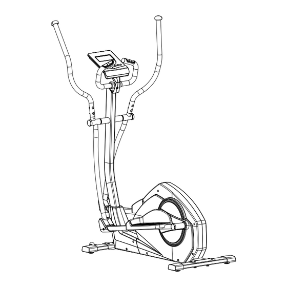
- Page 2 Exploded drawing.
- Page 3 G-7 G-8 G-5 G-6...
-
Page 4: Parts List
Parts List Description Number Q'ty Unit Console & Screw A, A-1 Front handlebar set Foam grip Hand pulse End cap Screw M4x20L Semi-circle washer 1.5T Wire for hand pulse Upper handlebar (Left) End cap Foam grip Upper handlebar (Right) Handlebar post Cable (upper) for console Screw M5xP0.8x12L Cover for console holder(Left) - Page 5 Inside cover for the disc F-15 Cross disc F-16 Flat washerφ5xφ16x1t F-17 Cap for the disc F-18 Front cover (Right ) F-19 Chain cover(Right ) F-20 Screw M5x16L F-21 Round disc F-22 Chain cover(Left) F-23 Self tapping screw F-24 Front cover (Left) F-25 Cover for the handlebar post F-26...
- Page 6 Assembly Stage #1 Attach the Front Stabilizer (J-4) to the Main Frame (F) using four Allen bolt (L-11) Attach the Rear Stabilizer (J) to the Main Frame (F) using four Allen bolt (L-11). Please remove the handlebar post cover (F-26) from the main frame (F). After assembly, the Trainer can be adjusted to slightly uneven ground by adjusting the height of the foot caps at the front and back.
- Page 7 Assembly Stage #3 L-15 1. Put pedal(K-5, K-6) onto the pedal arm and tighten it, using 4 knob (L-13), flat washers (L-12) (L-22), spring washer (L-14), sleeve and bolts(L-15) in each side Please note that the left and right pedals need to be placed in identical positions.
- Page 8 Assembly Stage #4 Please remove four sets of the Allen bolt (F-3) and Flat Washer (F-2)from the Main Frame (pt.F) 2. Take the Handlebar post (D) and pass it through the Handlebar post cover (F-26). 3. Hold the Handlebar Post (D) and connect the Lower Computer Cable (F-1) and the Upper Computer Cable (pt.
- Page 9 Assembly Stage #5 1. Disassemble one side of the pre-assembled screw (L-6) on axle, insert the axle into the whole movable handlebars and handlebar post . Then tighten the end using one plastic washer (L-7), flat washer (L-8), wave washer (L-9) and screw (L-6) in each side. carriage bolts 2.
- Page 10 Assembly Stage #7 Pass the hand-pulse wire (pt.B-6) through the handlebar post hole. Attach the Front handlebar (B) to the Handlebar post (D) using the clamp cover (L-18), and then fix with two Flat Washers (L-19), two Spring Washers (L-20), two Fixing Bolt (L-21).
- Page 11 Assembly Stage #8 M5*10L 1. Connect the Computer cables (D-1) and Hand pulse wire (pt.B-6) to the computer, then attach the Computer (pt .A-1) to the Computer bracket with the enclosed Screws (pt .A-2). Assembly Stage #9 M5*12L 1. Please remove four sets of the from the handlebar post (D) screw (D-2) 2.
- Page 12 and self tapping screw (L-1)
- Page 13 Assembly Stage #10 1. Assemble the upper handlebar (C, C-3) by carriage bolts (L-2) with nut (L-3) and semi-circle washer (L-4).
- Page 14 SE01 L-22: flat washer L-14: Spring *1T (4) L-7 : Teflon washer L-9:Curved Washer 17.5* 25*0.3T(4) *0.5T (4) L-8 : flat washer 10* *2T (4) L-6: Hex bolt L-4: Curved Washer for M8 bolt (4) M8*P1.0*20L(4)
- Page 15 SE01 L-21: Allen Bolt M7*P1.0*30L(2) L-2: Carriage Bolt L-10: lock nut for M8 (2) M8*P1.25*40L (4) L-15: Carriage Bolt M6*P1.0*50L (8) L-11: Allen Bolt M8*P1.25*16L 8pcs L-17 Washer L-1 Screw M3*25L(1) 16 t(2) L-16: allen bolt M8*P1.25*55L (2) L-3 :Acorn Nut for M8 Bolt (4) Box Spanner (2) L-19: flat washer 7* *1T (2)
- Page 16 COMPUTER INSTRUCTION MANUAL [BUTTON FUNCTION] MODE/ENTER In stop mode, the mode is to confirm all exercise data setting, and enter into progr RESET In stop mode, press the button back to main menu. START/STOP To start or stop exercise. RECOVERY To test hear rate recovery status.
- Page 17 4. Quick Start and Manual : Before exercise in Manual mode, user my set up TIME, DISTANCE, CALORIES and PULSE target. After power on, user may press START/STOP button to start exercise in MANUAL immediately without any setting. Level can be adjusted during exercise by press UP or DOWN.
Need help?
Do you have a question about the Everbright Rear Drive SE01 and is the answer not in the manual?
Questions and answers