Table of Contents
Advertisement
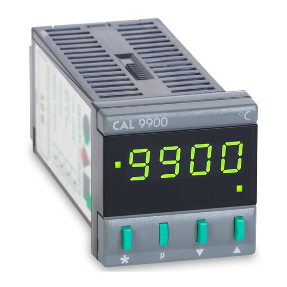
Install the 9900 controller in pone! see 10. 2
Wire up connections see 10 . 1
TO SELECT SENSOR AND ADJUST
SET POINT
Step l
POWER UP
Self check sequence
Step 2
ZERO FLASHES ON LEFT
Indicating no sensor
selected
Note
Buttons only adjust flashing digits
(shown green)
Step3
A
PRESS
TO SELECT
SENSOR e.g. Type K
�
2
Sensor options:
(For full table see 8)
l
R
J
E
4
s
K
2
L
5
N
3
T
6
8
Step4
p
PRESS
TO ENTER
SENSOR INTO MEMORY
Qisploy shows process
temperature e.g. Ambien
�
*
Steps
PRESS
TO
DISPLAY
SET POINT
($
*
Step 6
PRESS AND HOLD
&&
PRESS
TO INCREASE
A
SET POJNT
Output turns on and temperature rises
The controller is now
Prop bond 2.5%
operational with
Prop time
factory PIO settings:
Derivative 25 sec
Integral 5 min
DAC approach
control l.5
P l e a se re ad before using
2 I
MPORTANT
-
Autotune AT
If required adjust: Range. Hi-res 0.1 °.
Negative temperature ranging, see 8
Proportional cycle-time: 20 sec factory
2
set. if unsuitable change now or use
Autotune calculated value otter tuning
run see 6
3
For best results use normal set point
and load conditions
4
Start Autotune AT with the load cool
TO AUTOTUNE
Step 7
START AUTOTUNE 'AT'
NEAR AMBIENT
I
I
I
..
I
The CAL 9900 microprocessor based
temperature controller provides precise
control with a minimum of setting up, the
advanced Autotune algorithm tunes all
--------
five control parameters automatically.
The simple setting up procedure below is
normally sufficient. specialised applic
ations may need the comprehensive
9900 features covered in this manual.
Step 8
7
RTD 9
Pnoo
8
PRESS
10
PROGRAM MODE
Function O flashes
on right
*
Step 9
PRESS
TO OPTION SELECTION
Option O flashes
on left
Step 10
..
PRESS
A
AUTOTUNE 'AT'
Option l
Step 11
D
,..,...,..
......
t'l(C;);)
r'
AUTOTUNE 'AT'
20
sec
AT and Process
temperature displayed
alternately during
Autotune
3
AUTOTUNE TYPES AND USES
Two types of Autotune are provided to
ensure optimum control of a wide range
of applications
AUTOTUNE AT - Normal method. tunes
during warm up
AUTOTUNE PT - ( Push-to-Tune) - For
difficult applicolions. tunes at set point
.
3
1
AUTOTUNE AT
Start Autotune AT with the load cool. A short
tuning cycle occurs at 75% set point during
warm up. New PIO values ore automatically
entered and the temperature rises to set
point
p
TO ACCESS
TO CHANGE
TO SELECT
T-
r.TA .... ..,.
IV ;)l."\1(1
Hi.&.
SP.
LoT
Error
*
* ..,
View set point
Decrease
ik
.&.
Increase
KEY CONTENTS GUIDE
9
Important caution - please read first
10 Installation 1 Setting up
6
2, 3, 5
Autotune
Functions: 4 Selection
7 Alarms 11 Error messages
In Program Mode - Left of . is value, Right of . is parameter.
Autotuned parameters
Autotune limits
Entered automatically:
Proportional band/Gain
0.5 - 2C,
Integral time/Reset
0.2 - 43.5
Derivative time/Rate
l.0- 255 sec
DAC approach control
0.5 - 9.0 x gain
0. 8 - 81 9 sec
Calculated but for safety reasons needs
manual acceptance see 6
temp
set potnt
-
ATIU1'4ng
75'1. SP
onloH
I'/,
cycles
lu n ,ng
S t art
Ac.c
T
-l.L---..;.
-
'- -
� -
,
,
,
(100'1. output powe<)
Fig. 1 Autotune AT
3 2
AUTOTUNE PT (Push-to-Tune)
•
C.afa.,..f l"\""'t ') ,.f ? •+a .... 11""\
vv,v...,., "'""'' • ..,., • ••v,., ,....,
Used to fine tune difficult applications ot set
point. Useful if the set point or thermal
conditions are substantially changed. During
PT tuning some overshoot will occur. If this
is unacceptable, temporarily reduce set
point. PT tunes the parameters listed above
except DAC. Proportional cycle time is re
calculated but needs manual acceptance
remp
overshoot
Siert PI
d tJr, ng
tuning
setpotnt
:
·
\
\
-
�
P<OO
bond
I'/,
on/ott
cycles
tuning
I
-+---'-,-�
-��--'--hme
,
(100'1. output Power)
Fig. 2 Autotune PT
3.3
OVERIDING AUTOTUNE VALUES
After AT /PT any Autotuned parameter moy
be changed to an Option from the table.
The original Autotuned value is retained in
memory.
Note Subsequent Autotune AT or PT run
replaces manual selections with new
calculated values (except Cycle time)
Process
temperature
or set point
SPl
SP2
Prop cycle-time
a
Tobie
'°
c/ronge
min
new PIO volues
entllred ona
output power
re·Oppl,ed
-
tme
·
tuni ng PIO
new
PIO
volues
I
ente<ed
Advertisement
Table of Contents

Related Manuals for CAL Controls CAL 9900


Summary of Contents for CAL Controls CAL 9900
- Page 1 Self check sequence Error Step 2 ZERO FLASHES ON LEFT * .., Indicating no sensor View set point The CAL 9900 microprocessor based selected Decrease temperature controller provides precise .&. Increase control with a minimum of setting up, the Note...
- Page 3 FUNCTIONS AND OPTIONS TABLE Please read these Important notes first 3. Protected Functions: 5. Locating Functions: 1. Factory setting: is O ption 0 All Functions, except User Settings (Functions Function O is the Program mode entry point (except Functions 2 ond 22 ) l.
- Page 4 INSTALLATION: IMPORTANT SAFETY INFORMATION PLEASE REVIEW Designed for use: UL6 l O l 0- 1-Within 1. CONFIGURATION It is the responsibility of the installation Installation All functions ore front key selectable. engineer to ensure that this equipment's compliance to UL6 l010 is not impaired when it is the responsibility of the installing engineer to ensure that the fitted to the final installation and to use this...
- Page 5 13.4 MONITOR OPERATION (PM/DCM) IMPORTANT: SP2 latch alarms ADVANCED FUNCTIONS SECURITY Step Select Normal To start monotor: Fri 38/0pt The advanced functions ore intended for Latch To return to normal OEM's and process engineers. Access is operation PRESS therefore protected in the Function table Only for: SP2 ON/OFF mode.
- Page 7 5Vdc SSR drive 5A 250V SPDT relay Notes: These products are intended for indoor use only Field wiring employed must be rated for a minimum of 70°C. YDM00021B - Issue 05...
Need help?
Do you have a question about the CAL 9900 and is the answer not in the manual?
Questions and answers