Table of Contents
Advertisement
Quick Links
Advertisement
Table of Contents

Related Manuals for Hallicrafters HA-1


Summary of Contents for Hallicrafters HA-1
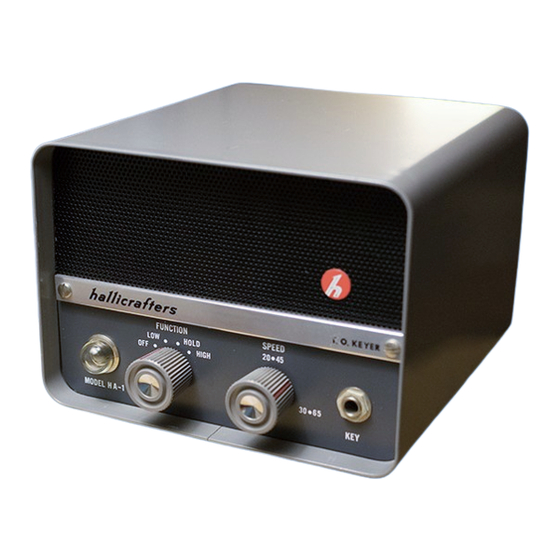
- Page 2 GENERAL 1-1. DESCRIPTION The Hallicrafters Model HA-1 T.O.Keyer ® employs digital circuitry, similar to that found in modern digital computers, to form perfect code characters at any speed. Experienced operators appreciate its stability and precision of operation, and novice operators discover a new command of CW that leads to proficiency and unsuspected enjoyment.
-
Page 3: Specifications
SECTION II SPECIFICATIONS POWER SOURCE ......105 to 125 volts, 60 cycles AC, 25 watts. SPEED RANGE ......Low: 10 to 30 WPM. High: 25 to 65 WPM. KEYING MONITOR ......Self-contained tone generator and PM speaker. Rear chassis mounted PHONES jack disconnects speaker when phones are inserted. -
Page 4: Installation
Various styles of commercially built key levers are available for use with electronic keyers. Any of these are suitable for use with the Model HA-1 keying unit. Connections to the key and panel jack are made as shown in figure 2. Key lever connections are also provided at the control socket on the rear of the unit (See paragraph 3-4-1-1). - Page 5 Receptacles are provided on the rear of the keyer for the following purposes. 3-4-1. CONTROL OUTLET (See figure 3) An eight-pin socket is provided to connect the Model HA-1 keying unit into the station control system. The mating connector for this socket is an Amphenol type CP-8 (one is supplied).
- Page 6 3-4-1-2.KEYING CONTACTS (Pin 2, 3 and 4) Pin 2 (normally open to ground) is normally used for transmitter keying purposes. Pin 3 and 4 (independent, normally closed to ground) are provided for auxiliary control of station facilities. IMPORTANT The mercury-wetted relay contact rating is 5 amperes maximum, or 500 volts maximum, the product not to exceed 250 voltamperes with contact protection.
- Page 7 The chart (figure 5) affords a convenient means of determining the necessary contact protection. Hallicrafters Model HT-30, HT-32, HT-32A, HT-32B, HT-37, HT-44, SR-150 and SR-160 Transmitters require no protection network when used with this keyer.
- Page 8 Example I: A circuit maintaining a load current of 2.0 amperes and an open circuit load voltage of 100 volts would require a C value of 0.4 µF and an R value of approximately 3.6 ohms. (See dotted lines on chart). Example II: Measured current and voltage is 50 mA and 150 V respectively.
- Page 9 Figure 5. Relay Contact Protection Chart.
- Page 10 SECTION IV FUNCTIONS OF OPERATING CONTROLS 4-1. FUNCTION SWITCH The FUNCTION control is a four-position rotary switch: (1) turns the unit ON and OFF, (2) selects low or high speed operation, and (3) has a center HOLD position for transmitter tuning purposes (key down). 4-2.
-
Page 11: Weight Control
4-5. WEIGHT CONTROL The WEIGHT control (knurled shaft), located on the rear panel, and referred to as the mark-space ratio adjustment, sets the time relationship of a dot (or mark) to its following space. For normal CW work this is usually set for a ratio of 1 to 1. -
Page 12: Operation
Care should be exercised in the selection of a key lever for use with the Model HA-1 keying unit; one incorporating good mechanical construction, particularly at the pivot and contact points, is a desirable and will provide long reliable service. -
Page 13: Theory Of Operation
formed and twice for each dash. In a perfectly formed character the rhythm of the flashes will be uninterrupted. SECTION VI THEORY OF OPERATION 6-1. GENERAL The keyer forms dots and dashes by the use of digital circuitry and logical sequencing. - Page 14 Figure 7. Model HA-1 Rear Oblique View. Figure 8. Model HA-1 Bottom Chassis View.
- Page 15 The sidetone signal is produced by a neon-type relaxation audio oscillator, amplified by V4B, and keyed by the relay. Frequency of the tone is determined by resistor R27 and capacitor C8. The sidetone level is controlled by potentiometer R28. The power supply incorporates an electrostatically shielded transformer to minimize possible RF pickup and to provide complete isolation from the power line.
-
Page 16: Service Data
7-3. TROUBLESHOOTING Throughout the design of the Model HA-1 keying unit, full consideration was given to keep maintenance problems at an absolute minimum. However, if a malfunction does occur, the voltage chart and schematic diagram will aid in isolating and correcting the malfunction. For the physical location of component parts, refer to figures 7 and 8. - Page 17 SERVICE AND OPERATING QUESTIONS For further information regarding operation or servicing of this equipment contact the dealer from whom the unit was purchased. The Hallicrafters Company maintains an extensive system of Authorized Service Centers where any required service will be performed promptly and efficiently at no charge if this...
Need help?
Do you have a question about the HA-1 and is the answer not in the manual?
Questions and answers