Table of Contents
Advertisement
Advertisement
Table of Contents

Subscribe to Our Youtube Channel
Summary of Contents for Cetus 3D Cetus
- Page 1 Cetus3D Cetus User Manual V 0.1 Cetus3D...
-
Page 2: Table Of Contents
Table of Contents Precautions Printer Body Accessories Install Print Head Installing Build Platform Installing the Software Software Interface Starting UP the Printer Setting the Nozzle Height Preparing for Printing Setting UP Wi-Fi Product Activation Loading a Model Printing a Model Pausing a Print Job Rotating a Model Scaling a Model... - Page 3 Table of Contents Using Customized Material Profile Converting a 2D Picture into a 3D Model Machine and Software Settings Printer Info and Naming a Printer Change Nozzle Cetus3D...
-
Page 4: Precautions
The USB cable can be unplugged after the data transfer is finished. The Cetus's ideal working temperature is between 15°C and 30°C with relative humidity between 20–50%. Users are recommneded to discharge any static charge from the body before touching the machine to prevent interruption of printing and any potential damage to the printer. -
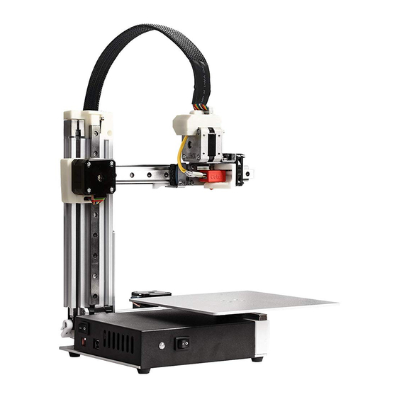
Page 5: Printer Body
Printer Body Print Head Z-axis Y-axis Build Platform X-axis USB Connector Power Power Main Board Case Connector Switch Cetus3D... -
Page 6: Accessories
Accessories Power Adapter Power Cable Scraper USB Cable Print Head Hex Keys Plier Nozzle Wrench 2.0mm, 2.5mm Build Plate Nozzles 0.2mm 0.4mm Cetus3D... -
Page 7: Install Print Head
Installing the Print Head Plug in print head cable Cetus3D... -
Page 8: Installing Build Platform
Installing the Build Platform The machine is pre-leveled in factory. There is no way and no need to level the build platform. Cetus3D... -
Page 9: Installing The Software
Install the Software Cetus temporarily use the UP Studio as its printing software. Please go to www.up3d.com to download the latest version. Mac users could go to Mac App Store to download the latest version. Cetus3D... -
Page 10: Software Interface
Software Interface Account UP (Print) Library Help Account Printer name Current Settings Material Share Nozzle & Platform Connection Printer Status Skin type Temperature Back to home Model Adjustment Add a Model/ wheel Picture Print Initialize Calibration Maintenance Build Space Move Mirror Rotate Save... -
Page 11: Starting Up The Printer
Starting Up the Printer Connect to power and computer as shown in the photo on the right. Turn on the machine using the power switch. Initialize the machine by clicking the "Initialize" button in the software menu Initialization is required every time the machine is switched on. -
Page 12: Setting The Nozzle Height
Setting the Nozzle Height 1. Go to Calibration. 2. Press button 5 to move print head to the middle of the build platform. 3. Use the + button to lower the print head to close proximity of platform. 4. Put a piece of paper in between the nozzle and the platform. -
Page 13: Preparing For Printing
Although ABS and ABS+ are temperature, e.g. for PLA, it is both available in the material list, 210°C. The printer will buzz and Cetus currently does not support the print head will start to extrude. these materials. Gently insert the filament into the small hole on the print head. -
Page 14: Setting Up Wi-Fi
Setting Up Wi-Fi Connecting to Cetus through Wi-Fi requires a Wireless Local Area Network (WLAN). The computer and the printers must connect to the same WLAN (same SSID) before they can communicate. In order to achieve stable Wi-Fi connection, It is highly recommended to use the printer under a capacious Wi-Fi environment. - Page 15 Wi-Fi Setup Connect Cetus to a computer through USB. At the top right corner click the printer tab Click the “Printer Detail” button. Cetus3D...
- Page 16 Click the dropdown menu to choose an available network. Choose your network from the drop down list. Cetus3D...
- Page 17 tier Input the password for the Wi-Fi network. If “Private” is set to ON, a private password can be optionally added to limit the printer access via Wi-Fi to trusted users. Please note that the password for private access is a weak protection that anyone who can connect the printer through USB connection can disable or change the password without any limitation.
-
Page 18: Product Activation
Product Activation It is highly recommended to activate Cetus as soon as possible to be able to access its unlimited printing power and the cloud based web functionality. The inactivated machine has limited printing times before the activation is done. -
Page 19: Loading A Model
Loading a Model Click "Import Mode or Image", choose to open a 3D model. Choose your model. Open Cancel The loaded model will appear on the print plate. Click "Print" to open the print preview window. Cetus3D... -
Page 20: Printing A Model
Printing a Model Make sure the printer is connected to a computer throug USB or Wi-Fi ( go to page 19 for details about Wi-Fi setting), and loaded a model. Click the print button to open the print interface Set Layer Thickness Please note that 0.05mm and 0.07mm layers are optimized for 0.2mm... -
Page 21: Pausing A Print Job
Pausing a Print Job An on-going print job can be paused by clicking the "Pause" button on the left hand side menu. Click the "Resume Print" to resume the paused print job. Once the print job is paused, the other buttons on the maintenance interface will be enabled. -
Page 22: Rotating A Model
Rotating a Model Choose the model and click the rotate button. Choose the rotation axis User could input a specific value or choose a preset value for rotation. Alternatively, user may use the rotation guide to rotate the model in real time by click and drag using mouse. -
Page 23: Scaling A Model
Scaling a Model Choose the model and click scale button. By default the scaling is in all axes. User could also choose a specific axis for scaling. User may input a specific scaling factor or choose a preset value. Click MM or INCH to convert the models to the size of corresponding units. -
Page 24: Moving A Model
Move a Model Choose the model and click the Move button. Choose the direction of movement. User may input a specific value or choose a preset value for the distance of movement. Alternatively, user may use the translational guide on the model to move on the X-Y plane or a single direction by click and drag using mouse. -
Page 25: Making Copies
Making Copies Choose the model by clicking it (hight lighted), then right-click to bring up the menu and select the number of copies. Repairing a Model If the model contains defective surfaces, the software will highlight the defective surfaces in red. Click the "More"... -
Page 26: Merging And Saving Models
Merging and Saving Models Ctrl/CMD-click all the models on the build plate. The Merge button on the second level of the adjustment wheel will become available. Click the "Merge" button to merge the models. Click the "Save" button to save the merged models to the comptuer. -
Page 27: Printing Preference
Print Preference Surface: The number of layers that sealing the top and the bottom of the printed object. Angle: This value determines at which angle the Surface layers start to be printed. Dense: Choose the number of the dense layers between the support structure and the supported surfaces. - Page 28 Print Preference No Raft: Print without raft. No Support: Print without support. Stable Support: Support structure will be stronger but harder to be removed. Unsolid Model: The software will autofix nonsolid models. Thin Wall: The software will detect the wall thickness that is too thin to print and expand the wall to a printable size.
-
Page 29: Printing Parameters
Printing Parameters Surface Infill Surface Support Dense (support) Raft Print Platform <30 <90 Dense: Solid support structure ensures that the surface being supported retains its shape and surface finish. Infill: The inner structure of the printed object. The density of the infill can be adjusted. Raft: The thick structure that assists with the adhesion of the object to the platform. -
Page 30: Using Customized Material Profile
Using Customized Material Profile It is possible to use customized material profile to control the printing temperature and platform temperature. This function is very useful for using third party materials that cannot print well using the preset profiles. The use the customized profile, go Maintenance and choose "Customize"... -
Page 31: Converting A 2D Picture Into A 3D Model
Converting a 2D Picture Into a 3D Model Click the “Add Picture” button and select a picture. Base Height determines the thickness The "Convert Negative" button of a flat layer that holds the picture. will reverse the pixel intensity so that user could choose the Model Height determines the contrast picture to be protruding from or of the final print. - Page 32 Converting a 2D Picture Into a 3D Model Update 3D model button. This button will convert the modified picture on the left to a 3D rendering on the right. OK button sends the 3D rendering to the 3D printing interface for printing.
-
Page 33: Machine And Software Settings
Machine and Software Settings Click the "Setting" button to bring up the menu Choose a Language Choose and Set the Printer's Name Printer Name and Wi-Fi Settings Privacy Setting Auto Update Setting Cetus3D... -
Page 34: Printer Info And Naming A Printer
Printer Info and Naming a Printer User could rename the printer by clicking the printer name on the status bar. Blackout Recovery A print job could be resumed after an electricity cutoff. The next time when the printer connects to a computer and after an initialization, a pop up window will appear to let the user choose to resume the interrupted print job. -
Page 35: Change Nozzle
Change nozzle While the machien is cold, remove the peek cap by hand. If cannot remove by hand, use a plier. Use the nozzle wrench provided to remove the nozzle. When install the new nozzle, just reverse the previous steps. Install the nozzle using the wrench, then put on the peek cap by hand, do not screw the cap too tight. - Page 36 This device complies with Part 15 of the FCC Rules. Operation is subject to the following two conditions: (1) this device may not cause harmful interference, and (2) this device must accept any interference received, including interference that may cause undesired operation. Changes or modifications not expressly approved by the party responsible for compliance could void the user's authority to operate the equipment.
Need help?
Do you have a question about the Cetus and is the answer not in the manual?
Questions and answers