Sony WM-GX100 Service Manual
Hide thumbs
Also See for WM-GX100:
- Operating instructions (2 pages) ,
- Operating instructions (2 pages)
Table of Contents
Advertisement
QQ
3 7 63 1515 0
SERVICE MANUAL
Ver 1.0 2000.10
• Frequency range
FM: 65.0 - 107.9 MHz (Eastern Europe)
TE
L 13942296513
87.5 - 108 MHz (Italy and Saudi Arabia)
87.6 - 108 MHz (North, Central and South America)
87.6 - 107.9 MHz (Other countries)
AM:526.5 - 1,606.5 kHz (Italy and Saudi Arabia)
530 - 1,710 kHz (North, Central and South America)
531 - 1,602 kHz (Other countries)
• Power requirement
– 3V DC batteries R6 (AA) x 2
– External DC 3 V power sources
• Dimensions
88.8 x 118.6 x 38.0 mm (3
• Mass
Approx. 160 g (5.7 oz)
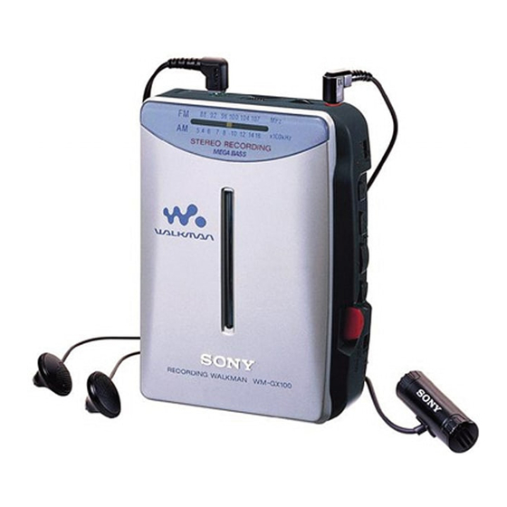
• Supplied accessories
Stereo headphones or Stereo earphones (1), Belt clip (1),
Stereo microphone (1)
Design and specifications are subject to change without notice.
www
.
http://www.xiaoyu163.com
1
3
1
⁄
x 4
⁄
x 1
⁄
inches) (w/h/d)
2
4
2
x
ao
u163
y
i
http://www.xiaoyu163.com
WM-GX100
2 9
8
Model Name Using Mechanism Type
Similar Mechanism Tape Transport
SPECIFICATIONS
Battery life (approximate hours) (EIAJ*)
Q Q
3
6 7
1 3
1 5
playback
radio
mic recording
radio recording
* Measured value by the standard of EIAJ (Electronic Industries
Association of Japan). (Using a Sony HF series cassette tape)
** When using LR6 (SG) Sony "STAMINA" alkaline dry batteries
(produced in Japan).
Note
• The battery life may be shorter depending on the operating condition,
the surrounding temperature and battery type.
RADIO CASSETTE-CORDER
co
.
9 4
2 8
E Model
Chinese Model
WM-SR1
MF-WMSR1-114
Sony alkaline LR6 (SG)**
0 5
8
2 9
9 4
2 8
Sony R6P (SR)
24
7
50
16
11
3.5
10
2.5
m
9 9
9 9
Advertisement
Table of Contents

Related Manuals for Sony WM-GX100


Summary of Contents for Sony WM-GX100
- Page 1 * Measured value by the standard of EIAJ (Electronic Industries – 3V DC batteries R6 (AA) x 2 Association of Japan). (Using a Sony HF series cassette tape) – External DC 3 V power sources ** When using LR6 (SG) Sony “STAMINA” alkaline dry batteries •...
-
Page 2: Table Of Contents
http://www.xiaoyu163.com 3 7 63 1515 0 TABLE OF CONTENTS Flexible Circuit Board Repairing • Keep the temperature of the soldering iron around 270°C during repairing. Specifications ................1 • Do not touch the soldering iron on the same conductor of the circuit board (within 3 times). -
Page 3: Disassembly
http://www.xiaoyu163.com SECTION 2 DISASSEMBLY 3 7 63 1515 0 The equipment can be removed using the following procedure. Mechanism deck Cabinet (rear) Main board Motor (M901), “Head, Magnetic” (HRP901) (MF-WMSR1-114) “Holder sub ASSY, Cassette” Note : Follow the disassembly procedure in the numerical order given. 2-1. -
Page 4: Main Board
http://www.xiaoyu163.com 3 7 63 1515 0 2-2. MAIN BOARD Main board 3 Screw (M1.4) 1 Remove solder (4 places) (M901) 2 Head flexible board 4 Claws (CN301) L 13942296513 2-3. MECHANISM DECK (MF-WMSR1-114) Mechanism deck (MF-WMSR1-114) 1 Claws u163 – 4 – http://www.xiaoyu163.com... -
Page 5: Motor (M901), "Head, Magnetic" (Hrp901)
http://www.xiaoyu163.com 3 7 63 1515 0 2-4. MOTOR (M901), “HEAD, MAGNETIC” (HRP901) How to apply the belt 1 Belt Wheel ASSY (NP), capstan M901 Belt 4 “Head, Magnetic” 3 Motor (M901) (HRP901) 2 Screws (M1.4) L 13942296513 2-5. HOLDER SUB ASSY, CASSETTE 1 Move hinge awsy from projection Hinge... -
Page 6: Setting The Pointer
http://www.xiaoyu163.com 3 7 63 1515 0 CAUTIONS DURING “HOLDER SUB ASSY, CASSETTE” ASSEMBLY 4 Holder sub ASSY, cassette 1 Spring (tortion) 3 Close the “Holder sub ASSY, cassette” then press it L 13942296513 2-6. SETTING THE POINTER Pointer 2 Install the pointer and align it with A section Pointer 1 Turn the tuning knob in the arrow direction... -
Page 7: Adjustments
http://www.xiaoyu163.com SECTION 3 ADJUSTMENTS 3 7 63 1515 0 3-1. MECHANICAL ADJUSTMENTS Adjustment Location : PRECAUTION RV601 : Tape speed Adjustment 1. Clean the following parts with a denatured-alcohol-moistened swab : playback head pinch roller capstan rubber belt 2. Demagnetize the playback head with a head demagnetizer. Do not use a magnetized screwdriver for the adjustments. - Page 8 http://www.xiaoyu163.com 3 7 63 1515 0 • Repeat the procedures in each adjustment several times, and the frequency coverage and tracking adjustments should be finally done by the trimmer capacitors. < > : Saudi Arabia model AM IF ADJUSTMENT Adjust for a maximum reading on level meter. 455kHz AM FREQUENCY COVERAGE ADJUSTMENT Adjust for a maximum reading on level meter.
-
Page 9: Diagrams
WM-GX100 SECTION 4 DIAGRAMS 3 7 6 3 1 5 1 5 0 4-1. BLOCK DIAGRAM (1/2) TUNER L/R RV601 TAPE SPEED TUNER L TUNER R MIC AMP, ALC REC/PB AMP S303 (4/4) IC341 (2/2) IC341 (1/2) (REC/PB) COMPARATOR TH601 –... -
Page 10: Block Diagram (2/2)
WM-GX100 3 7 6 3 1 5 1 5 0 4-2. BLOCK DIAGRAM (2/2) 10.7MHz FM/AM RF AMP, FM/AM MIX AMP, FM/AM OSC, FM/AM IF AMP, DET, MPX FM RF FM/AM TUNER L/R B.P.F. MIX OUT 10.7MHz L-OUT IF IN... -
Page 11: Printed Wiring Boards
WM-GX100 4-3. PRINTED WIRING BOARDS 3 7 6 3 1 5 1 5 0 Semiconductor Location Ref. No. Location D101 G-10 D102 G-10 D301 CT1-4 CT1-1 D302 D305 D306 D308 RV301 D309 w VOLUME D405 CT1-3 CT1-2 D502 D503... -
Page 12: Schematic Diagram (1/2)
WM-GX100 3 7 6 3 1 5 1 5 0 4-4. SCHEMATIC DIAGRAM (1/2) Refer to page 19 - 20 for IC Block Diagrams. Refer to page 19 for Notes. Refer to page 19 for Waveforms. 1 3 9 4 2 2 9 6 5 1 3... -
Page 13: Schematic Diagram (2/2)
WM-GX100 3 7 6 3 1 5 1 5 0 4-5. SCHEMATIC DIAGRAM (2/2) Refer to page 19 - 20 for IC Block Diagrams. Refer to page 19 for Notes. Refer to page 19 for Waveforms. 1 3 9 4 2 2 9 6 5 1 3... - Page 14 http://www.xiaoyu163.com 3 7 63 1515 0 Note on Schematic Diagram: Waveforms Note: • All capacitors are in µF unless otherwise noted. pF: µµF 50 WV or less are not indicated except for electrolytics and tantalums. • All resistors are in Ω and W or less unless otherwise 80 mVp-p specified.
- Page 15 http://www.xiaoyu163.com 3 7 63 1515 0 IC301 LA4585M-TLM 25 24 23 22 PRE 2 PRE 1 LOW BOOST – PRE REV IN 2 IN 2 H.P. 2 L.P. 1 PRE REV IN 1 PRE FWD IN 1 PRE FWD IN 2 LOW BOOST NF VREF LOW BOOST SW...
-
Page 16: Exploded Views
http://www.xiaoyu163.com SECTION 5 EXPLODED VIEWS 3 7 63 1515 0 NOTE : • -XX, -X mean standardized parts, so they • The mechanical parts with no reference • Abbreviation may have some difference from the original number in the exploded views are not : Saudi Arabia one. -
Page 17: Mechanism Deck Section
http://www.xiaoyu163.com 3 7 63 1515 0 5-2. MECHANISM DECK SECTION (MF-WMSR1-114) HRP901 M901 HE901 L 13942296513 Ref. No. Part No. Description Remark Ref. No. Part No. Description Remark 3-703-816-73 SCREW (M1.4), SPECIAL HEAD 3-923-530-01 SLEEVE (M) 3-704-197-01 SCREW (M1.4), SPECIAL HEAD X-3369-749-1 PINCH LEVER (N) ASSY 3-728-091-01 WASHER, STOPPER 3-920-996-01 SPRING (PINCH N) -
Page 18: Electrical Parts List
http://www.xiaoyu163.com SECTION 6 MAIN ELECTRICAL PARTS LIST 3 7 63 1515 0 NOTE : • Due to standardization, replacements in the • SEMICONDUCTORS When indicating parts by reference num- In each case, u : µ , for example : parts list may be different from the parts ber, please include the board. - Page 19 http://www.xiaoyu163.com MAIN 3 7 63 1515 0 Ref. No. Part No. Description Remark Ref. No. Part No. Description Remark C265 1-164-156-11 CERAMIC CHIP 0.1uF < FILTER > C301 1-164-346-11 CERAMIC CHIP 1-767-733-71 FILTER ASSY, CERAMIC C302 1-162-638-11 CERAMIC CHIP 1-527-870-00 FILTER C303 1-165-176-11 CERAMIC CHIP 0.047uF...
- Page 20 http://www.xiaoyu163.com MAIN 3 7 63 1515 0 Ref. No. Part No. Description Remark Ref. No. Part No. Description Remark 1-416-627-11 COIL (WITH CORE) R103 1-216-835-11 METAL CHIP 1/16W (FM FREQUENCY COVERAGE) (EA) 1-416-626-11 COIL (WITH CORE) R104 1-216-837-11 METAL CHIP 1/16W (FM FREQUENCY COVERAGE) (E,9E,CH,TW) R105...
- Page 21 WM-GX100 MAIN 3 7 63 1515 0 Ref. No. Part No. Description Remark Ref. No. Part No. Description Remark R381 1-216-857-11 METAL CHIP 1/16W MISCELLANEOUS R601 1-216-857-11 METAL CHIP 1/16W ************** R602 1-216-857-11 METAL CHIP 1/16W R603 1-216-857-11 METAL CHIP...
Need help?
Do you have a question about the WM-GX100 and is the answer not in the manual?
Questions and answers