Table of Contents
Advertisement
Advertisement
Table of Contents

Summary of Contents for Southern States VM-1
- Page 1 Type VM-1 Motor Operator All Ratings INSTALLATION & INSTRUCTION MANUAL...
- Page 2 The Quality Name in High Voltage Switching...
-
Page 3: Safety Information
Portions of it may not be applicable or may not have complete instructions for your specific equipment. If you do not understand any part of these instructions or need assistance, contact Southern States Service Division at 770-946-4562 during normal business hours (8:00am – 4:30pm EST, M-F) or 770-946-4565 after... -
Page 4: Limited Warranty
The Quality Name in High Voltage Switching LIMITED WARRANTY Southern States, LLC (“SSLLC”) warrants only to the Warranty Holder (hereinafter defined as the “End User” or the “Immediate Purchaser”, as applicable, pursuant to the terms and conditions of this Limited Warranty as set forth below), that the Product identified below will, upon shipment, be free of defects in workmanship and material for the applicable Warranty Period. - Page 5 The Quality Name in High Voltage Switching TYPE VM-1...
-
Page 6: Table Of Contents
Southern States reserves the right to make changes in the specifications shown herein or to make improvements at any time without notice or obligations. Should a conflict arise between the general information contained in this publication and the contents of drawings or supplementary material, or both, the latter shall take precedence. -
Page 7: Unpacking
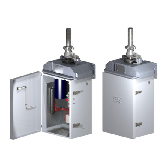
Figure 1 - Part Identification Storage: If this equipment is to be stored prior to use: 1. Store the VM-1 mechanism in the upright position 2. The door should be latched closed 3. No part of the mechanism should be submerged 4. -
Page 8: Installation
Installation: 1. Mount the VM-1 Mechanism as shown on the Operating Mechanism Drawing or Mounting Arrangement Drawing. Refer to Switch Installation Instructions for switch adjustment. 2. Attach the upper decoupler member to the vertical pipe in accordance with the instructions provided for the decoupler type supplied. - Page 9 Installation and Adjustment Procedures 4. Single Size Decoupler: ●Do not pierce the pipe with the self-piercing set screws at this time. ●The vertical pipe should bottom out in the upper decoupler member. ●A clearance of ½ inch must be maintained between the upper and lower decoupler members. To adjust, raise or lower the vertical pipe in the vertical bearing.
-
Page 10: Electrical Check-Out Procedure
VM-1 decoupled from the switch 2. Decouple as shown in Figure 3 and connect the VM-1 mechanism for electrical operation as shown on the wiring diagram drawing. Refer to Figure 1 for conduit entry into the cabinet. -
Page 11: Adjusting Switch Operation To Vm-1 Rotation
Mechanism drawing and switch installation instructions for this procedure. 2. Perform all trail operations manually. Refer to Figure 4. 3. Do not rotate the VM-1 past the open and/or close position locks. Over rotation can damage the switch and operating mechanism. -
Page 12: Manual Operation
1. Complete adjustments of switch and operating mechanism. 2. MAKE SURE MANUAL ROTATION OF THE SWTICH MATCHES THE ELECTRICAL ROTATION OF THE VM-1 MECHANISM. 3. Remove the manual operating handle and test electrical operation of the switch. 4. NOTE: The stop button when supplied will override all other commands. -
Page 13: Changing Output Rotation
2. Loosen the adjustable lock plate and disengage-Refer to Figure 5. 3. Manually rotate the VM-1 mechanism to the desired position. (See Figure 6) Adjust the motor limit switches to stop the motor at the new position as described in section IX. The limit switches are the two top poles of the auxiliary switch. -
Page 14: Auxiliary Switch Adjustment
Installation and Adjustment Procedures Auxiliary Switch Adjustment: 1. Each auxiliary switch contact is spring loaded. 2. A contact is opened and held open by a cam operating against a roller – Refer to Figure 8. 3. The Auxiliary switch is adjustable in infinite steps to open and close at any point in the line switch operation. - Page 15 Installation and Adjustment Procedures 6 mm Figure 7 - Auxiliary Switch...
- Page 16 Installation and Adjustment Procedures Procedure for Setting Auxiliary And Limit Switch Contacts Factory Settings: ┤├ Closed in counter-clockwise limit position (CCW). (Figure 8) ┤├ Closed in clockwise limit position (CW). (Figure 9) All Illustrations Shown From Above Limit Switches Figure 8 - CCW – LS Figure 9 - CW –...
-
Page 17: Reverse Motor Rotation
1. Motor Mechanisms are factory wired to rotate in the direction indicated on the switch operating mechanism drawing or customer’s order. 2. Refer to notes on the VM-1 wiring diagram should it become necessary to reverse rotation. 3. All auxiliary contacts must be readjusted after changing leads. Follow procedure described on 11. - Page 18 30 Georgia Avenue Hampton, Georgia 30228 Phone: 770-946-4562 Fax: 770-946-8106 E-mail: support@southernstatesllc.com http://www.southernstatesllc.com ©2015 Southern States, LLC IB-501-VM1-Rev 1 100815 Printed U.S.A.
Need help?
Do you have a question about the VM-1 and is the answer not in the manual?
Questions and answers
How do we reverse rotation
To reverse rotation on the Southern States VM-1:
1. Refer to the notes on the VM-1 wiring diagram to change motor lead connections.
2. Ensure the VM-1 is decoupled from the switch before starting.
3. Pull motor fuses and heater fuses, and place the overload toggle switch in the off position.
4. After reversing leads, readjust all auxiliary contacts using the procedure described.
5. Keep the VM-1 decoupled until all adjustments are complete.
This answer is automatically generated