
Related Manuals for Eagle A3 Super 3


Summary of Contents for Eagle A3 Super 3
-
Page 1: Instruction Manual
A3 SUPER INSTRUCTION MANUAL For Firmware Version 1.0, Data Version 1.0 Aug 1, 2017 Revision support@hobbyeagle.com... -
Page 2: Table Of Contents
CONTENTS IMPORTANT NOTES ……..……………………………………………………………………….…………..3 Introduction …….…………..……………………………………………………………….……………..4 Setup Procedure Overview ………………………………………………………………….…………..5 Installation …………………………………………………………………………………….…………..6 Receiver & Servos Connection …………………………………………………………….………….8 4.1. Port Description ……………..…………………………………………………………….…………..8 4.2. Supported Wing Type …….……………………………………………………………….………...8 4.3. Using Pass-through Function of [A2] & [E2] …..………………………………………….………..9 4.4. Standard Receiver Connection (for Electric Planes) ………………………………….………..10 4.5. -
Page 3: Important Notes
IMPORTANT NOTES Always turn on the transmitter before power on the plane and the gyro. After Power on, A3 Super 3 needs to perform an initialization which includes the gyroscope calibration and stick centering. Keep the plane still and wait for the gyro to initialize, the initialization will take about 2 seconds and the LED will blink blue several times. -
Page 4: Introduction
Thank you for purchasing our products. A3 Super 3 (hereinafter referred to as A3S3) is a high-performance and functional 6-axis gyro and stabilizer designed for R/C airplanes. This gyro can be used with nearly any size and type of R/C airplanes and it will make the flying even easier and comfortable. -
Page 5: Setup Procedure Overview
SETUP PROCEDURE OVERVIEW The procedure below will show you how to install and setup the A3S3 step by step. PREPARING YOUR PLANE Before installing the gyro, make sure that the plane is well installed, connect all the control surfaces to the servos and make them center by adjusting the linkages. -
Page 6: Installation
CHECKING FOR GYRO DIRECTIONS Switch to normal mode, check the gyro direction for each channel one by one, and reverse it if the gyro reacts in the wrong direction on the Gyro tab of the software. This procedure is extremely important because an opposite reaction of the gyro could lead to losing control or even crash after takeoff! See Page 15 “6. - Page 7 Flat: Flat Inverted: face up, socket pointing to rear. face down, socket pointing to rear. Upright: Upright Inverted: [DATA] up, socket pointing to rear. [DATA] down, socket pointing to rear. CAUTION You need only one piece of the tapes each time, a soft or thick mounting may probably impact the performance of the gyro.
-
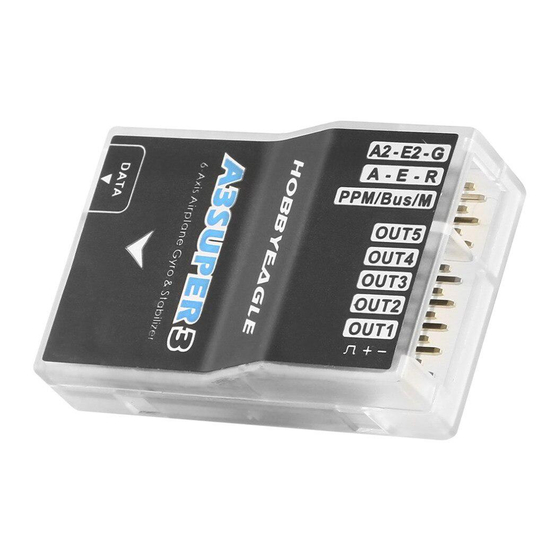
Page 8: Receiver & Servos Connection
RECEIVER & SERVOS CONNECTION A3S3 has 7 separate input channels which used to connect to the receiver and 5 output channels for servos, and supports standard receivers and PPM or Futaba’s S.BUS(or S.BUS 2) single-line receivers. There are 7 different wing type available for airplane. -
Page 9: Using Pass-Through Function Of [A2] & [E2]
Flying-Wing (Delta-wing) V Tail CAUTION Again make sure that there are no mixing functions active on your transmitter. Have a look at the radio’s servo monitor and verify that each stick controls only one output channel (except for aileron stick which controls aileron and aileron 2 if dual aileron is used, or elevator stick which controls elevator and elevator 2 if dual elevator is used). -
Page 10: Standard Receiver Connection (For Electric Planes)
The pass-through function of [A2] and [E2] are also available when using a standard receiver. For example, if 2AIL+1ELE+1RUD type is selected, the [E2] is free so you can connect it to the throttle channel of the receiver and get the ESC or throttle servo connected at [OUT5], it is just the same as connecting the ESC or throttle servo directly to the receiver. -
Page 11: Standard Receiver Connection (For Nitro/Gas Planes)
CAUTION Pay attention to the polarity of the plugs. The orange signal line must always be on the top and the brown on the bottom. Check all the connectors and make sure that all of them are firmly connected to the sockets. Please refer to the instructions of your transmitter for setting up the 3-position switch for flight mode control, and the knob (or slider) for remote master gain control. -
Page 12: Ppm, S.bus Single-Line Receiver Connection
4.6. PPM, S.BUS SINGLE-LINE RECEIVER CONNECTION Using a single-line receiver (e.g. PPM receiver or Futaba’s S.Bus receiver) all channels are transferred by one single wire which connected to [PPM/Bus/M]. When a single-line receiver type has been selected, A3S3 will load the default channel assignment to recognize the channels from receiver. - Page 13 Programming the channel assignment in the software. support@hobbyeagle.com...
-
Page 14: Flight Mode
FLIGHT MODE A3S3 provides 6 different flight modes which can be changed by a 3-position switch (or 6-position logic switch) of the transmitter during flight. GYRO-OFF MODE Solid Red Gyro-Off mode is usually used for testing purpose only. When this mode is selected, the gyro will be deactivated completely. The plane will be completely under the control of your transmitter as it was before installing the gyro. -
Page 15: 3-Position Mode Switching
AUTO-HOVER MODE Fast Flashing Violet The Auto-Hover mode provides the same functionality as the Auto-Level mode. The only difference is that when you release the sticks, the plane will be brought to vertical position (nose up) and keeps hovering. This flight mode is designed to help you to learn hovering maneuver and reduce the probability of crashing. - Page 16 Check the gyro direction in aileron direction Quickly move the right wing downward around the roll axis, the right aileron surface should flap down and the left flap up as shown below. Check the gyro direction in elevator direction Quickly move the nose of the plane downward around the pitch axis, the elevator surface should flap up as shown below. Check the gyro direction in rudder direction Quickly move the nose of the plane to the left around the yaw axis, the rudder surface should flap right as shown below.
-
Page 17: Gain Settings
GAIN SETTINGS Basic Gain Basic gain determines the momentary reaction strength of the gyro. The momentary correction exists and plays an important role in all flight modes except off mode. Basic gain is the basis of all gain settings and it will directly affect the performance of the gyro in all flight modes. -
Page 18: Led Descriptions
plane in the vertical direction. If the gain is too low, the plane will lean sideways while hovering. In order to get firmly hovering, you can simply set the hover gain to maximum. Response Gain The response gain is used to adjust the control behavior of the gyro. It determines how sensitive the A3S3 will react to stick inputs for aileron, elevator and rudder. -
Page 19: Install The Usb Driver
9.1. INSTALL THE USB DRIVER Run the USB driver installer and follow the instructions to complete the installation of Silicon Laboratories CP210x VCP driver, as shown below. After setup, insert the USB adapter into the PC and wait until the windows finishes scanning and installing the new hardware. -
Page 20: Overview Of The Software
9.2. OVERVIEW OF THE SOFTWARE Double-click the icon on your desktop to run the software, you will get the following GUI. [1] Main Menu Click the icon on the top-left corner will pop up a menu that contains the most commonly used functions. You can change the language between English, Simplified Chinese and Traditional Chinese in the menu, after change the language, you need to restart the software to make the new language take effect. -
Page 21: Flight Mode
9.3. FLIGHT MODE [1] Flight Mode Type Choose either 3-position or 6-position switch for flight mode control. [2] Flight Mode Preset Assign the desired flight mode for each position of the switch, blue background color is used to indicate the position currently selected when you flipping the switch. -
Page 22: Mount Orientation
9.5. MOUNT ORIENTATION Choose the mounting orientation of your A3S3. The orientation in the picture should look as same as yours. 9.6. GYRO SETTINGS [1] Gyro On-Off You can disable the gyro separately for each channel. [2] Gyro Direction Reverse the gyro if it reacts in opposite direction. [3] Gain Settings Adjust the gain of each axis for each flight mode. -
Page 23: Radio Settings
9.7. RADIO SETTINGS [1] Receiver Type Selection Choose your receiver type then restart the gyro to make the new setting take effect. [2] Channel Monitor The channel monitor displays the stick positions for each channel graphically and numerically. [3] Stick Reverse Change the direction of an individual servo’s response to a stick input. -
Page 24: Servo Settings
Step 1: Neutral Calibration for [Gain] and [Mode] Move the mode switch and gain control knob (or slider) to their center positions, the progress bar [MOD] and [GAIN] should be in the right position of 0%. If not, adjust the Sub-Trim setting of your transmitter to fix it. -
Page 25: Servo Trimming
9.8.1. Servo Trimming This function allows you to adjust the center position of the servos using the transmitter. It will be more convenient and more intuitive. Click the “Servo Trimming” button to enter the setting procedure in the “Servo” page. After entering, move the elevator stick up or down to select one of the servos connected at [OUT1] to [OUT5] (the pass-through channels will be skipped automatically). -
Page 26: Travel Limiting
9.8.2. Travel Limiting This function allows you to adjust the travel limits of the servos using the transmitter. It will be more convenient and more intuitive. Click the “Travel Limiting” button to enter the setting procedure in the “Servo” page. After entering, move the elevator stick up or down to select one of the servos connected at [OUT1] to [OUT5] (the pass-through channels will be skipped automatically). -
Page 27: Sensor Monitor
9.9. SENSOR MONITOR [1] Real-time Chart of the Gyroscope Reading Display the real-time reading of the gyroscope graphically. [2] Real-time Chart of the Accelerometer Reading Display the real-time reading of the accelerometer graphically. [3] Attitude Indication Display the real-time angle on roll and pitch axes. [4] Level and Hover Offset &... -
Page 28: Level Calibration
9.9.1. Level Calibration When flying in Trainer mode or Auto-Level mode, A3S3 needs to know the angle of the plane in both roll and pitch direction, this is achieved by calculating the attitude of its own. A small angle deviation caused by installation can lead to an unexpected behavior when flying in Trainer mode or Auto-Level mode. -
Page 29: Hover Calibration
9.9.2. Hover Calibration As a same reason, a hover calibration is recommended to perform after installation if you want to fly with Auto-Hover mode. The procedure is quite similar to that of level calibration. The only difference is in the first step. Before calibrating, you need to lift the plane and make it vertical to the ground instead of putting it on the ground. -
Page 30: Accelerometer Calibration
9.9.3. Accelerometer Calibration Before leaving the factory every unit has been carefully tested and calibrated. Usually you don’t need to perform a calibration of the accelerometer during use. However, in some specific cases, we’d suggest you re-calibrate the accelerometer to obtain better performance, these include special conditions such as temperature changes those will probably cause the mechanical characteristics changes of the sensor. - Page 31 Now turn the gyro around and fix it with the sticker showing down, press “Next” to continue and wait until the Step 3 calibration is done, just like the last step. Now stand it up with the arrow pointing to the table. Fix it with your fingers and make sure it is vertical to the Step 4 desktop.
- Page 32 Now turn the gyro around and fix it with the arrow pointing upwards, press “Next” to continue and wait until Step 5 the calibration is done. Now change to another orientation and make the gyro look like it is in the picture, with the long side of the Step 6 housing on the table and the [DATA] socket up.
- Page 33 Now turn the gyro around and make the [DATA] socket down. Again fix it with your fingers and press “Next” to Step 7 continue and wait until the calibration is done. After you have finished all of the steps above, you can see the new calibration results of each axis on the Step 8 screen.
-
Page 34: Advanced Settings
9.10. ADVANCED SETTINGS Changing the advanced settings incorrectly can lead an abnormal phenomenon of the gyro system. If you are not sure, it is recommended to leave all settings as their default. [1] Stick Deadband The stick deadband is the range around the very center of the sticks at where the controller will not react. Some transmitters have the problem that when the sticks are brought back after an input, they are not exactly at the same center position as before which may generate a deviation on the corresponding function, in this condition, you can increase the setting of stick dead band to fix it. -
Page 35: Program Card
PROGRAM CARD If you have purchased a full set of A3S3, a programming card is included to let you program the gyro more easily instead of using a PC or a laptop. The modifications made via the box will take effect immediately without a final confirmation and you just need to simply pull out the box when you have finished the setting. -
Page 36: Function List (V3.5)
10.7. FUNCTION LIST (v3.5) 01. Switch Type Choose the type of the flight mode control switch, 3-position or 6-position. Preset the flight mode for each position of the switch, when 3-position switch type is selected, the options of POS-4, POS-5 and POS-6 will be unavailable. 【OFF】 Gyro-Off Mode, 【NORM】 02. - Page 37 Set the EXP of aileron, elevator and rudder for 05.AutoLevel Mode Auto-Level mode, from -100% to +100%. Set the EXP of aileron, elevator and rudder for 06.AutoHover Mode Auto-Hover mode, from -100% to +100%. Assign the channel number for each channel when using a PPM or 05.
-
Page 38: Specifications
SPECIFICATIONS 32-bit MCU Main Controller Sensors High-precision 3-axis gyroscope and 3-axis accelerometer ±2000dps Gyroscope Scale Range ±4g Accelerometer Scale Range 920uS ~ 2120uS with 1520uS center length / 50~333Hz Input Voltage 4.8V~8.4V Operating Temperature -10℃~50℃ Size 43×27×14mm Weight 10g (excluding wires) * VOLTAGE PROTECTOR It’s recommended to use the supplied 3300uF/16V capacitor to get a more stable and secure working voltage for the gyro.