
Summary of Contents for Federal Signal Corporation SS2000 Plus
-
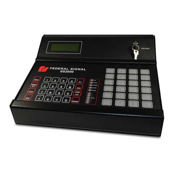
Page 1: Installation And Operation Manual
SS2000+ Encoder/Decoder Installation and Operation Manual 255400 Rev. C1 1216 Printed in U.S.A. © Copyright 2016 Federal Signal Corporation... -
Page 2: Limited Warranty
A copy of this limited warranty can also be obtained by written request to Federal Signal Corporation, 2645 Federal Signal Drive, University Park, IL 60484, email to info@fedsig.com or call +1 708-534-3400. -
Page 3: Table Of Contents
Contents Safety Messages............................. 7 General Description ..........................9 Introduction ............................9 Features ............................. 9 Encoding ........................... 10 Modes of Operation ........................10 Standalone Two-way Operation ....................10 Computer Mode Operation ......................10 Automatic Logging ........................10 Testing and Alignment ........................11 Audio Inputs ..........................11 Serial Ports ..........................11 Relay Outputs ..........................11... - Page 4 Using the SSLoader+ Software ......................25 Using the General Configuration Tab ....................25 Digital Communications ......................25 DTMF Communications ......................26 Descriptions of Functions Reported by RTUs–Sent to Printer ..........27 Comm Port Parameters ......................27 General Parameters ........................28 Relay Functions ........................
- Page 5 Computer Mode ........................49 Encoding ............................49 Manual Activation ..........................51 Activating All Sites ........................51 Activating a Zone ........................51 Activating an Individual Site ...................... 52 Menu Selection ..........................53 Sending the Calibration Tone ....................53 Setting the Date and Time ......................54 Executing the Self Test ......................
- Page 6 Tables Table 1 Electrical ..........................13 Table 2 Signaling Formats ........................13 Table 3 Transceiver Interface Port ..................... 13 Table 4 Local Mic Input ........................14 Table 5 External Mic Input ........................14 Table 6 Line Input ..........................14 Table 7 Ethernet Network Connection ....................14 Table 8 Environmental .........................
-
Page 7: Safety Messages
Safety Messages Safety Messages It is important to follow all instructions shipped with this product. This device is to be installed by trained personnel who are thoroughly familiar with the country electric codes and will follow these guidelines as well as local codes. Listed below are important safety instructions and precautions you should follow: Important Notice Federal Signal reserves the right to make changes to devices and specifications detailed in... - Page 8 Safety Messages • After installation, service, or maintenance, test the siren system to confirm that it is operating properly. Test the system regularly to confirm that it will be operational in an emergency. • If future service and operating personnel do not have these instructions to refer to, the siren system may not provide the intended audible warning and service personnel may be exposed to death, permanent hearing loss, or other bodily injury.
-
Page 9: General Description
General Description General Description Introduction This manual describes the features, specifications, installation, and how to use the SS2000+ encoder. The SS2000+ encoder monitors and controls your siren system. The SS2000+ supports one-way communication with the option of two-way communications using DTMF or FSK encoding. -
Page 10: Encoding
General Description • Monitor Speaker to Monitor Incoming and Outgoing Traffic • Powered from 12 to 30 Vdc, runs on standard 12 or 24 V backup power Encoding Program up to three codes under each activation input. There are sixty programmable functions available. -
Page 11: Testing And Alignment
General Description Testing and Alignment The SS2000+ has a calibrate function and an LED bar graph to aid in setting receive and transmit levels. It also incorporates a comprehensive built in test routine to test every circuit of the unit. The internal monitor speaker allows the user to hear all incoming and outgoing transmissions to aid in system setup and troubleshooting. -
Page 12: Transceiver Interface
General Description Transceiver Interface The transceiver interface features a balanced 600 ohms input and output (optional 10 K ohms) and can accept a wide range of transceiver types and levels. The transmit audio from other encoding equipment can be interrupted during the transmissions of the SS2000+ by the PTT relay. -
Page 13: Specifications
Specifications Specifications Table 1 Electrical D.C. Power Input Input Voltage 12-30 Vdc Current Draw <300 mA Standby, <700 mA max Table 2 Signaling Formats MSK Digital encode/decode 1200 Baud Decode Sensitivity </= 21 dB SINAD for highest modem tone DTMF encode/decode 35 ms/5 ms-100 ms/100 ms timing Two-Tone encode 282-3000 Hz,... -
Page 14: Table 4 Local Mic Input
Specifications Table 4 Local Mic Input Type Dynamic, non-amplified mic Levels 10-150 mV nominal input, 10 K ohms Table 5 External Mic Input Balanced, Low Impedance 10-150 mV for non-amplified Dynamic mic. 30-570 mV for amplified Sensitivity adjustable from; 10 K ohms Impedance with VOX Jumper Selectable for Amplified mic, 48 Vdc Phantom power Table 6 Line Input... -
Page 15: Connectors, Indicators, Controls And Jumpers
Connectors, Indicators, Controls and Jumpers Connectors, Indicators, Controls and Jumpers Figure 3 Drawing of back of SS2000+ Controller Board Connectors DC Power In – External Center – 12-30 Vdc input Outside – GND Relay Outputs - External 1 – Aux 1 Common 2 –... -
Page 16: Figure 4 Back Of Ss2000
Connectors, Indicators, Controls and Jumpers Transceiver Interface - External 1 – PTT Common 2 – PTT Normally Open 3 – PTT Normally Closed 4 – Local TX Audio, audio is disconnected when SS2000+ transmits 5 – TX Audio Hi 6 – TX Audio Low 7 –... - Page 17 Connectors, Indicators, Controls and Jumpers Ethernet Port - External 1 – TXD+ 2 – TXD- 3 – RXD+ 4 – EPWR+ 5 – EPWR+ 6 – RXD- 7 – EPWR- 8 – EPWR- Line Level Inputs – External Top Tip – Input # 2 Top Ring –...
-
Page 18: Remote Activation Inputs Board Connectors
Connectors, Indicators, Controls and Jumpers Figure 5 Back of SS2000+ Remote Activation Inputs Board Connectors Remote Input Board Addressing Buttons 01 - 20, 21 - 40, 41 - 60, Remote Activation Inputs 1 – 5 - External 1 – Remote Activation Input # 1 2 –... - Page 19 Connectors, Indicators, Controls and Jumpers Remote Activation Inputs 1 – 5 - External 8 – Iso GND 9 – Remote Activation Input # 5 10 – Iso GND Remote Activation Inputs 6 – 10 - External 1 – Remote Activation Input # 6 2 –...
-
Page 20: Indicators
Connectors, Indicators, Controls and Jumpers Indicators Display LEDs • LCD Display • AUX LED • TX DATA • TRANSMIT • RX DATA • RECEIVE • Receive Signal Level, 5 LED Bars SS2000+ Encoder/Decoder... -
Page 21: Controls
Connectors, Indicators, Controls and Jumpers Figure 6 LEDs Controls The following table provides the description of the controls in the back of the SS2000+. V2 (TX LEVEL) Transmit Audio Level V3 (RX LEVEL) Receive Audio Level V4 (MIC LEVEL MNC) Local Mic Input Level V5 (MONITOR) Monitor Speaker Level... -
Page 22: Jumpers
Connectors, Indicators, Controls and Jumpers Figure 7 Controls on the SS2000+ Jumpers DTMF Decode Speed Jumpered = 35 ms/5 ms Open = 50 ms/50 ms External Mic Amplified or not Jumpered for amplified mics JU4A Receive Audio Input Impedance Center and Upper pins Jumpered = 10 K ohms Center and Lower pins Jumpered = 600 ohms JU4B Transmit Audio Output Impedance... -
Page 23: Installation
Installation Installation Programming the SS2000+ To program the SS2000+, do the following: 1. Connect a USB cable between your computer and the port labeled P1 on the SS2000+ with the plug adaptor. (Use serial port adaptor with part number 2005204 and the six conductor telephone cable with part number 1751134.) Figure 8 Port labeled P1 2. -
Page 24: Describing Ssloader+ Software
Installation Describing SSLoader+ Software Use the SSLoader+ Software is to configure and active functions on the SS2000+. Table 10 SSLoader+ Icons Opens an INI file on your computer. Saves an INI file to your computer. Sends an INI file to the SS2000+. Reads an INI file from the SS2000+ to your computer. -
Page 25: Reading Ini File From Ss2000
Using the SSLoader+ Software Reading INI file from SS2000+ To read the INI configuration file from the SS2000+, do the following: 1. Click the Read Ini File to SS2000 button to send the INI file to the SSLoader+. An information dialog box appears. 2. -
Page 26: Dtmf Communications
Using the SSLoader+ Software Field Description 128 Bit Encryption radio button Enter your Encryption key to secure your SS2000+. The default Encryption key is all zeros. 256 Bit Encryption radio button Enter your Encryption key to secure your SS2000+. The default Encryption key is all zeros. Security Code By default, the security code is 65535, which means that the security code is open. -
Page 27: Descriptions Of Functions Reported By Rtus-Sent To Printer
Using the SSLoader+ Software Descriptions of Functions Reported by RTUs–Sent to Printer When a site is polled, it reports back the last function number that was run. This is where the name and description for the functions are entered. These names and descriptions are sent to the printer when the site reports back. -
Page 28: General Parameters
Using the SSLoader+ Software General Parameters The following shows the General Parameters group box of the General Configuration tab. Field Description AutoReport Delay Enter the number of seconds to wait after activating a function before requesting a report. The range is 0 to 99 seconds. Report Request Timeout Enter the number of seconds to wait for a response from a Report Request before trying again or moving onto another... -
Page 29: Relay Functions
Using the SSLoader+ Software Field Description Front Porch Time Enter the number of milliseconds between when the SS2000+ keys up a transmitter and when it begins sending the codes. The range is 100 to 9999 milliseconds (0.1 to 9.9999 seconds). Inter-Code Gap Time Enter the number of milliseconds the SS2000+ waits between the end of one transmitted code and the beginning of the next. -
Page 30: Rtu Faults
Using the SSLoader+ Software RTU Faults The following shows the RTU Faults group box of the General Configuration tab. The RTU Faults group box lets you select the conditions considered a fault by the SS2000+. The columns are divided into mechanical and electronic type sirens. Field Description Mechanical RTU Faults... -
Page 31: Network Settings
Using the SSLoader+ Software Network Settings The following shows the Network Settings Frame group box of the General Configuration tab. The Network Settings group box allow you to configure how the SS2000+ connects to an Ethernet network. Field Description Enable Ethernet Communications Check to enable this group box settings. Obtain IP Address Automatically Click to negotiate with the network for an IP address when it is connected. -
Page 32: Using The Activation Function Tab
Using the SSLoader+ Software Using the Activation Function Tab Activation Function The following shows the Activation Functions group box of the Activation Function tab. Field Description Spin box—Button # Select the button to configure. Function Name Enter the name of the function. Symbols such as the equal sign = and the semicolon ;... - Page 33 Using the SSLoader+ Software Field Description Comment Sent to Enter a description that is sent to the printer during the activation. Printer when this Function is activated Two-Tone Select TwoTone from Activation Codes to display the Two-Tone group box. To save, click Save.
- Page 34 Using the SSLoader+ Software Select EAS from Activation Codes to display the EAS group box. To save, click Save. Field Description Origin Code EAN—Emergency Action Notification Network PEP—Primary Entry Point System WXR—National Weather Service CIV—Civil authorities EAS—Broadcast station or cable system Event Code Select an event code from the from the list.
- Page 35 Using the SSLoader+ Software Federal Digital Select Federal Digital from Activation Codes to display the Federal Digital group box. To save, click Save. Field Description Site numbers or ranges Enter the site numbers or ranges for numbers separated of numbers separated by by commas.
- Page 36 Using the SSLoader+ Software Field Description Off Time Enter how many seconds the relay waits after the activation to close. The range is 0-999. On Time Enter how many seconds the relay stays close. The range is 0-999. HotKey Select HotKey from Activation Codes to display the Hot Key group box. To save, click Save.
-
Page 37: Ss2000+ Activation Button Numbering
Using the SSLoader+ Software Call Function Key# Select Call Function Key# from Activation Codes to display the Call Activation Button group box. To save, click Save. Field Description Call Activation Button # Select the organization code from the list. SS2000+ Activation Button Numbering The following graphic shows the numbering of the activation buttons on the SS2000+ Installation and Operation Manual... -
Page 38: Uploading Ini File To The Ss2000
Using the SSLoader+ Software Uploading INI File to the SS2000+ To upload the INI configuration file to the SS2000+ using SSLoader software, do the following: Click the Send Ini File to SS2000 button to upload a file to the SS2000+. The following warning appears. -
Page 39: Balanced Interface
Using the SSLoader+ Software Figure 9 Unbalanced Interface Connections (TB2) SS2000+ TRANSCEIVER INTERFACE GROUND CAR DET CARRIER DET RX AUD LO RX AUD HI RX AUD +DE-EMPHASIZED/MUTE TX AUD LO TX AUD HI TX AUD LOC TX AUD PTTNC PTTNO PTT-N.O. -
Page 40: Setting The Jumpers
Using the SSLoader+ Software Figure 10 Balanced Interface Connections (TB2) SS2000+ TRANSCEIVER INTERFACE GROUND CAR DET CARRIER DET RX AUD LO BALANCED RX AUD RX AUD HI DE-EMPHASIZED/MUTED TX AUD LO BALANCED TX AUD TX AUD HI LOC TX AUD PTTNC PTTNO PTTCOM... -
Page 41: Setting The Levels
Using the SSLoader+ Software Setting the Levels Setting the Transmit Levels To set the levels on the SS2000+, do the following: 1. On the SS2000+, press the MENU button. 1. Printer Status 2. Send Calibrate 3. Set Date and Time 4. -
Page 42: Setting The Receive Level
Using the SSLoader+ Software Setting the Receive Level Inject a radio signal modulated by a 1 kHz tone at 1.5 kHz (3 kHz for wideband) of deviation into the transceiver. Using V3, set the level on the level meter until the first two LEDs are on, and then slowly increase the level until the third LED just comes on OR set TP11 for 1VP-P (354 mV NOTE: Configure RTUs in the field with at least a 500 ms front porch to be used with the... -
Page 43: Configuring The Ss2000+ For Operation Over Ethernet
Using the SSLoader+ Software Configuring the SS2000+ for operation over Ethernet The SS2000+ needs to be configured for the following: • Use the following IP Address (ObtainIPAddress=manual). • IP Address is set to a Static address set aside for the SS2000+. •... - Page 44 Using the SSLoader+ Software The following dialog box appears. 5. If the SS2000+ appears in the list, select it and then click Next . 6. If the SS2000+ is not in the list, select <Device not listed> and then click Next. The following dialog box appears.
- Page 45 Using the SSLoader+ Software The following dialog box appears. 11. Select the com port to use, and then click Next. The program installs the drivers and configures the com port. The following dialog box appears. 12. Click Finish and the SS2000+ is available on the virtual com port . Installation and Operation Manual...
-
Page 46: Using The Ss2000
Using the SS2000+ Using the SS2000+ Unlocking the System The SS2000+ keypad is secured with a key lock switch. When the key is in the LOCK position, the LCD displays Keypad Locked message, time, and date. ** Keypad Locked ** SS2000+ 07:29 06/19/2015 (c) When the key is turned to the UNLOCK position, the keypad is enabled and the standby... -
Page 47: Communication Mode
Using the SS2000+ Whenever the SS2000+ attempts to transmit, the following occurs: If the radio channel is busy and Carrier Detect is active, the LCD displays the following. F01: Function Name Waiting for Carrier The SS2000+ waits ten seconds for the channel to clear before transmitting. b. - Page 48 Using the SS2000+ When a Report - All is executed, the SS2000+ polls the units in the Digital list and logs each poll and response. When complete, the SS2000+ polls the units in the DTMF list, converting the DTMF reply to the same format as the Digital information and logs each poll and response.
-
Page 49: Computer Mode
Using the SS2000+ Computer Mode Requesting Reports and Polling Any poll requests or activation commands from Commander software are examined by the SS2000+ for time and date. The SS2000+ updates its internal clock to match, and then sends the Digital message. When Commander sends a poll request, the SS2000+ LCD displays the following. - Page 50 Using the SS2000+ Cycling the 3 Relay Outputs • Off times and on times 0 to 999 seconds Calling another activation key The 24 activation buttons activate functions 1 to 24. You can use the rear mounted activation to activate functions 1 to 20 or you can modify jumpers to use the rear mounted inputs as additional activation inputs.
-
Page 51: Manual Activation
Using the SS2000+ Manual Activation From the STANDBY screen, press the MANUAL ACT button The SS2000+ LCD displays the following. Manual Activation Select: ALL ZONE or SITE MANUAL ACTIV STANDBY Activating All Sites To activate all sites, do the following: 1. -
Page 52: Activating An Individual Site
Using the SS2000+ 4. Press the SEND button. The SS2000+ prompts for the Function. Enter Function: 1-50, 97=Cancel 98=QuietTest 99=Rset MANUAL SEND to START 5. Enter the function number. Press the CLEAR button to stop the process and return to the STANDBY screen. Activating an Individual Site To activate an individual site, do the following: 1. -
Page 53: Menu Selection
Using the SS2000+ Menu Selection The following section explains how the use the SS2000+ menu section. To view the menu selection, press the MENU button. The SS2000+ LCD displays the following. 1. Printer Status 2. Send Calibrate 3. Set Date and Time 4. -
Page 54: Setting The Date And Time
Using the SS2000+ After 10 seconds, the SS2000+ LCD displays the following. SEND to Transmit CLEAR to Quit 4. Press SEND to send the tone for another 10 seconds or press CLEAR or MENU to return to the STANDBY screen. Setting the Date and Time To set the date and time, do the following: 1. -
Page 55: Getting Service
Getting Service Getting Service If you are experiencing any difficulties, contact Federal Signal Customer Care at: 800-548-7229 or 708-534-3400 extension 5822 or Technical Support at: 800-524-3021 or 708-534-3400 extension 7329 or through e mail at: techsupport@fedsig.com. For instruction manuals and information on related products, visit: http://www.fedsig.com/ Installation and Operation Manual... - Page 56 2645 Federal Signal Drive University Park, Illinois 60484-3617 www.fedsig.com Customer Support 800-548-7229 • +1 708 534-3400 Technical Support 800-524-3021 • +1 708 534-3400...
Need help?
Do you have a question about the SS2000 Plus and is the answer not in the manual?
Questions and answers