Advertisement
Quick Links
Advertisement

Related Manuals for Vishay PS-1020

Summary of Contents for Vishay PS-1020
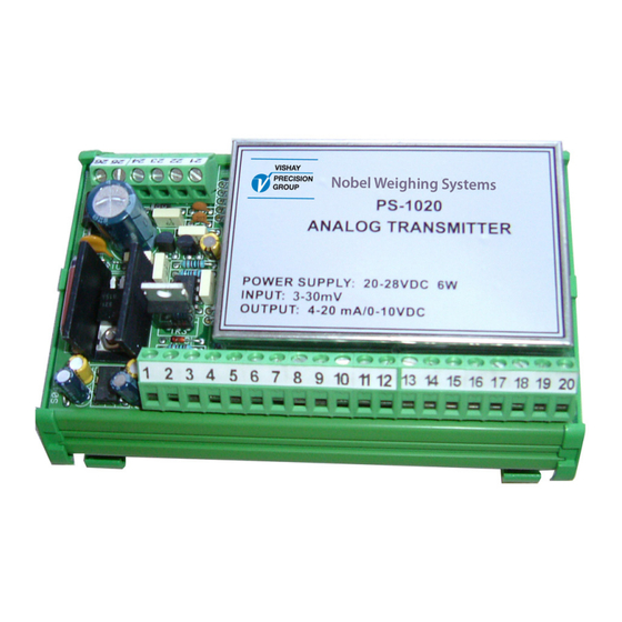
- Page 1 Analog Weight Transmitter PS-1020 Installation and Operating Manual...
- Page 2 ...
-
Page 3: Table Of Contents
Calibration Procedure ..........8 Section 3, Options 24 V Power Supply, PS-121 ........11 Appendices EC DECLARATION OF CONFORMITY for Analog Weight Transmitter PS-1020 ... Appendix 1 EC DECLARATION OF CONFORMITY for 24 V Power Supply PS-121 ....Appendix 2... -
Page 4: Ec Declaration Of Conformity For 24 V Power Supply Ps-121
... -
Page 5: Section 1, General Information
SECTION 1 GENERAL INFORMATION Introduction PS-1020 Analog Transmitters are electronic devices utilizing solid-state integrated components. They provide the user with a selectable voltage or current output directly proportional to the input signal within a specified linearity. Description The transmitters are intended for field mounting close to the vessel site, thereby reducing installation costs. -
Page 6: Specifications
Mounting DIN rail mount Material ABS Plastic Weight 215 gram Wiring Connections terminal blocks, pitch 5 mm OPTIONS 230 VAC Power Supply DIN rail mount Vishay BLH is continually seeking to improve product quality and performance. Specifications may change accordingly... -
Page 9: Section 2, Calibration
SECTION 2 CALIBRATION Prior to calibrating the instrument perform the following calculations. This will enable you to determine where the dip-switches should be positioned for zero and span. Obtain the capacity and full scale output of the transducer/s from the calibration certificates. If required, convert them into the engineering units being used in the system. -
Page 10: Calibration Procedure
Calibration Procedure Remove the metal cover to expose the dip-switches, jumpers and trim pots as shown in Figure 2 below. Set the zero and span dip-switches so the calculated values are within the minimum and maximum mV ranges given in Tables 1 and 2. - Page 11 Calibration Procedure (cont’d) Apply a known weight and adjust the fine span trim pot for the correct output. Turning the trim pot clockwise increases the output while turning it counter clockwise decreases the output. Re-check “zero” and “span” calibration and re-adjust if required. Replace the metal cover after calibration has been completed.
- Page 12 TABLE 2 Span Adjustment Dip-switches 12.2 11.6 16.5 15.2 24.7 FIGURE 3 Analog Filter Adjustment Filter Adjustment J2 removed = No Filtering J2 installed = Filter Activated...
-
Page 13: Section 3, Options
SECTION 3 OPTIONS 24 V Power Supply, PS-121 Specifications Power Input Voltage 230 Vac, 50/60 Hz Output Voltage 24 Vdc (nominal) Power Consumption 10 VA maximum Fuse T 160 mA Isolation Class II Environmental Operating Temp. Range -10 to +40ºC Storage Temp. - Page 14 Replace the front cover on the power supply. • Re-apply AC voltage to the unit. In the event of a malfunction, please contact the nearest Vishay service office for assistance. Any attempt to modify or repair the power supply will void the manufacturers warranty.
- Page 15 APPENDIX 1...
- Page 17 APPENDIX 2...
- Page 18 ...
- Page 19 ...
- Page 20 Document no. 35202 Article no. 600 690 R2 © Vishay Nobel AB, 2011-06-22 Subject to changes without notice. Vishay Nobel AB Box 423, SE-691 27 Karlskoga, Sweden Phone +46 586 63000 · Fax +46 586 63099 pw.se@vishaypg.com www.weighingsolutions.com...
Need help?
Do you have a question about the PS-1020 and is the answer not in the manual?
Questions and answers