Table of Contents
Advertisement
Available languages
Available languages
Quick Links
Advertisement
Table of Contents

Subscribe to Our Youtube Channel
Summary of Contents for Dynacord DPC 8015
- Page 1 OWNER‘S MANUAL BEDIENUNGSANLEITUNG DPC 8015 DPC 8120 Digital Paging Console...
-
Page 2: Table Of Contents
Paging Console CONTENTS 1 Introduction ............. . . 4 1.1 System overview . -
Page 3: Important Safety Instructions
EVI Audio GmbH products: Telex, Dynacord, ElectroVoice, Midas Consoles, KlarkTeknik and RTS. Arrangements are made with the dealer where you purchased the equipment from, for the returning of all unusable equipment at no cost, to the fac- tory in Straubing, for environmental protective disposal. -
Page 4: Introduction
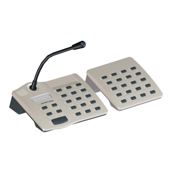
The PROMATRIX 8000 system includes the DPC 8015 paging console and the DPC 8120 paging console extension. The DPC 8015 employs a gooseneck microphone, 15 programmable function keys and 5 preprogrammed menu keys. Up to 3 alarm keys or key-locked switches can be retrofittted. The DPC 8015 employs a lighted LC-display (122 x 32 pixel). - Page 5 Paging Console DPC 8120 1 Paging console extension DPC 8120 1 Connection wire 6-pole 1 Connector plate 1 Connector 6 Screws (self-tapping) 1 Technical Information 1 Labeling template 1 Warranty card Keep the original invoice that states the purchase/delivery date together with the warranty certificate at a safe place.
-
Page 6: Description
Paging Console 2 Description Top view Selection buttons Selecting single zone or group with green/yellow LEDs Optional Key-Slots For up to 3 covered buttons or key-locked switches POWER LED Green if power supply active FAULT LED Yellow if a fault occured ALARM LED Red if alarm is active Microphone... - Page 7 Paging Console Bottom view EXT interface Interface for DPC 8120 paging console extension PCA BUS port Interface for PROMATRIX 8000 System Controller LINE/PTT interface Interface for external audio source or PTT switch MIC interface Interface for external microphone EXTENSION ADDRESS DIP switch for address selection of paging console extension Owner‘s Manual...
-
Page 8: Indications
Paging Console 2.1 Indications The following table provides you with an overview of the most important LED-indications. Status Description No group or area selected Selection (green) lights green Area or group selected / special function activated Group or area available flashing Group or area busy (alarm signal) Selection (yellow) -
Page 9: Factory Presets
The paging stations provide the following factory pre-set functions and characteristics: Parameter Setting / Description CAN address 0 (disconnected) 5 (priority for messages) Priority DPC 8015 Name Setup menu password protected, Default-Passwort: 2222 Password Pre-gong signal Buzzer On (acoustic alert signal) -
Page 10: Operation
Paging Console 3 Operation 3.1 LC-display Depending on the actual operational status of the PROMATRIX 8000 system, the LC-display shows information on time, operation mode, user notes, setting up, fault messages including precise device / module specification, etc. Status messages During error free operation of the PROMATRIX 8000 system the LC-display shows the name / description of the paging console in line 1 and the current date and time in line 2. - Page 11 Paging Console Operation mode Setup mode Pressing the PROGRAM button selects the program assign In setup mode this (PROGRAM) mode. The selection keys are used in this mode to assign a button is used to program (background music) to the desired areas or groups. select next The PROGRAM LED lights while being in the program assign...
- Page 12 Paging Console higher priority signals, the TALK LED will vastly blink and the calling attempt is ignored (also refer to the description of indications). The TALK LED lights during the transmission of an announcement. The TALK button has to be pressed during the whole message.
- Page 13 Paging Console Selective Alarm NOTE: The launch of an alarm does not depend on a paging console’s priority setting it had been activated from. Launching an alarm is possible from any microphone terminal at any time, even when the system is in stand-by mode. A running alarm is optically and occasionally also acoustically indicated at every paging station.
-
Page 14: Paging Console Configuration In Setup Mode
Paging Console The second line of the LC-display indicates the description of the programs, as they were definied during configuration via IRIS-Net. 3. Pressing a single or several selection buttons assigns the outputted program (background music) to the selected areas and groups. If the yellow LED of a selection key lights, the program can not be assigned to this area or group. -
Page 15: User Menu
Paging Console Menu structure Operation mode PROGRAM PROGRAM 1 - 4 PROGRAM + ON Program 1 Volume 1 Program assignment Program 4 Pre-Gong Volume 4 Buzzer Setup Menu SETUP Date / Time CAN address LCD contrast CAN baudrate CAN termination LCD brightness Firmware version LED test... - Page 16 Paging Console Program X The list of available programs is shown. Select a program by pressing the buttons. If there are already areas or groups assigned to the currently selected program, the corresponding green selection LEDs are lit. Pressing a single or several selection keys assigns the outputted program (background music) to the selected areas and groups.
-
Page 17: Lcd Contrast
Paging Console Date / Time The connected paging stations allow setting the date and time of the PROMATRIX 8000 system. Pressing the button opens the Date / Time dialog box, which allows selecting day, month, year, hour, minute or seconds by pressing the buttons. -
Page 18: Setup Menu
Paging Console Setup Menu Pressing the button opens the Setup sub menu, see following section. If this menu item is not available it has to be activated via the Password dialog box. 3.5 Setup menu CAN address Pressing the button opens the CAN address dialog box where the user can select the CAN address of the paging console in the range of 1 to 16 using the buttons. -
Page 19: Appendix
4.3 Paging console extension Up to five paging console extensions DPC 8120 can be connected to a paging console DPC 8015. The paging console extension provides 20 freely programmable function or zone keys having a green and yellow LED each. - Page 20 2. Put paging console and paging console extension side by side and upside down. (the illustration below shows the installation of two DPC 8120 to a DPC 8015) 3. Connect EXT ports of paging console and paging console extension using the connection wire (3) (the connector has to snap into the port) 4.
-
Page 21: Optionally Available Accessories
Paging Console 4.4 Optionally available accessories The paging console DPC 8015 employ three empty slots for retrofitting optional alarm keys or key-lock switches. For installing an additional alarm key you should only use the EB DPC (Artikel D 121 963) extension kit. -
Page 22: Interface Description
4.5 Interface description PCA BUS interface The PROMATRIX CAN Audio (PCA) BUS interface is used for connecting the DPC 8015 paging console to the PROMATRIX 8000 system. The 8-pole RJ-45 connector provides power supply, control interface (CAN bus), and audio connections. The microphone terminal has to be connected to a corresponding RJ- 45 wall outlet using the supplied connection cord (3 m). - Page 23 LINE interface used for PTT contact For connecting an external PTT microphone to the DPC 8015 the LINE interface is used as input for the PTT contact. The PTT function of the corresponding paging station has to be configured during system...
- Page 24 Paging Console configuration via IRIS-Net software. The following figure shows the correct assignment of a 3,5 mm jack for using the LINE interface as PTT contact input. Illustration 4.4: Assignment of LINE interface as PTT contact input MIC interface The mic interface allows connecting an external microphone. A standard „PC microphone” (V = 3,3 V) can be used.
- Page 25 Paging Console Owner‘s Manual...
-
Page 26: Inhalt
Paging Console INHALT 1 Einführung ..............28 1.1 Systemübersicht . -
Page 27: Wichtige Sicherheitshinweise
EU-Staaten bitten wir Sie, sich an Ihren örtlichen Händler zu wenden. Wir haben ein eigenes System zur Verarbeitung elektronischer Abfälle und gewährleisten die kosten- freie Entgegennahme aller Produkte der EVI Audio GmbH: Telex, Dynacord, ElectroVoice, Midas Consoles, KlarkTeknik und RTS. Wir haben mit dem Händler, bei dem Sie Ihr Produkt gekauft haben, eine Vereinbarung getroffen, dass alle nicht mehr verwenbaren Geräte zur umweltgerech-... -
Page 28: Einführung
Paging Console 1 Einführung 1.1 Systemübersicht Zum PROMATRIX 8000 System gehören die Sprechstelle DPC 8015 und die Sprechstellen-Erweiterung DPC 8120. Die Sprechstelle ist mit einem Schwanenhals-Mikrofon ausgestattet und verfügt standardmäßig über 15 frei programmierbare Auswahl- bzw. Funktionstasten und 5 vorprogrammierte Menü-/Funktionstasten. - Page 29 Paging Console DPC 8120 1 Sprechstellen-Erweiterung DPC 8120 1 Verbindungskabel für Sprechstellen-Erweiterung, 6-polig 1 Verbindungshalter für Sprechstellen-Erweiterung 1 Verbindungsplatte für Sprechstellen-Erweiterung 6 Schrauben (selbstschneidend) 1 Technische Informationen 1 Beschriftungsvorlage 1 Garantiekarte Überprüfen Sie bitte, ob die Garantiekarte vollständig ausgefüllt ist, denn nur so können Sie etwaige Garantieansprüche geltend machen.
-
Page 30: Gerätebeschreibung
Paging Console 2 Gerätebeschreibung Oberseite Auswahltasten Kreisauswahl- und Gruppenwahltasten mit grüner und gelber LED Optionale Tasteneinbauplätze Für bis zu 3 Alarmtaster oder Schlüsselschalter POWER LED Leuchtet grün wenn Spannungsversorgung ein ist FAULT LED Leuchtet gelb wenn ein Fehler aufgetreten ist ALARM LED Leuchtet rot wenn eine Alarmierung läuft Mikrofon... - Page 31 Paging Console Unterseite EXT-Schnittstelle Anschluss für DPC 8120 Sprechstellen-Erweiterung PCA BUS Schnittstelle Anschluss an PROMATRIX 8000 System Controller LINE-/PTT-Schnittstelle Anschluss für externe Audiogeräte oder eine PTT-Taste MIC-Schnittstelle Anschluss für externes Mikrofon EXTENSION ADDRESS DIP-Schalter zur Adress-Einstellung der Sprechstellen-Erweiterung Bedienungsanleitung...
-
Page 32: Anzeigen
Paging Console 2.1 Anzeigen Nachfolgend sind die Bedeutungen der LED-Anzeigen der Sprechstelle zusammengefasst. Zustand Beschreibung Kreis oder Gruppe nicht ausgewählt Zone (grün) grün leuchtend Kreis oder Gruppe ausgewählt / Sonderfunktion aktiviert Kreis oder Gruppe nicht belegt gelb blinkend Kreis oder Gruppe belegt (Alarmierung oder Räumung) Zone (gelb) •... -
Page 33: Auslieferungszustand
CAN-Adresse (1-16) zugewiesen werden. Die Sprechstellen werden werksseitig mit folgenden Funktionen und Eigenschaften programmiert: Parameter Einstellung/Beschreibung CAN-Adresse 0 (disconnected) Priorität 5 (Priorität für Durchsagen) Name DPC 8015 Setup-Menü passwortgeschützt, Default-Passwort: 2222 Passwort Vorgong Summer Ein (akustisches Warnsignal) Kompressor Alarmtasten Nicht konfiguriert... - Page 34 Paging Console Parameter Einstellung/Beschreibung Auswahl der Kreise 1 bis n (Taste 1 = Kreis 1, Taste 2 = Kreis Auswahltasten 1-n 2 usw.) Ruf in ausgewählte Kreise, Priorität 5 SPRECHEN Tastenbele- Ein- / Ausschalten der Anlage, Priorität 5 ON ( ) gung Programmzuteilung in ausgewählte Kreise PROGRAM ( )
-
Page 35: Betrieb
Paging Console 3 Betrieb 3.1 Funktionen der Sprechstelle Das beleuchtbare LC-Display mit 122 x 32 Pixel zeigt je nach aktuellem Zustand der Anlage Zeitinformationen, Betriebszustände, Benutzerhinweise, Setup-Informationen, Fehlermeldungen mit genauen Geräte-/Modulbezeichnungen usw. an. Statusanzeige im LC-Display Während des normalen Betriebs im Durchsage-Modus werden im LC-Display der Name der Sprechstelle (Zeile 1) sowie das Datum und die Uhrzeit (Zeile 2) angezeigt. - Page 36 Paging Console Durchsage-Modus Menü-Modus ESC (STOP) Durch Betätigen der Taste STOP wird ein laufendes Alarm- Für die Menüführung oder Gongsignal bzw. die Textwiedergabe abgeschaltet. Es wird diese Taste als können in der Regel nur solche Signale beendet werden, die ESC-Taste, also zum von der jeweiligen Sprechstelle ausgelöst wurden.
- Page 37 Paging Console Durchsage-Modus Menü-Modus ALARM Diese Taste dient zum Starten eines Alarmsignals, das in pro- grammierbare Kreise übertragen wird. Die Alarm-LED blinkt, sobald der Alarm ausgelöst wird. Durch Drücken der Taste STOP wird der Alarm wieder gestoppt. Die Art des Alarms wird während der Konfiguration der PROMATRIX Anlage fest- gelegt.
- Page 38 Paging Console Genereller Alarm HINWEIS: Auslösung eines Alarms ist unabhängig von der Priorität der Sprechstelle, von der aus er aktiviert wird. Es kann konfiguriert werden, von welchen Sprechstellen ein Alarm ausgelöst werden kann. Bei entsprechender Konfiguration kann ein Alarm auch dann ausgelöst werden, wenn sich die Anlage im Standby-Zustand befindet.
-
Page 39: Sprechstellen-Konfiguration Im Menü-Modus
Paging Console Im ausgeschalteten Zustand (Standby) ist die zugehörige LED aus. Durch Drücken auf die Taste ON wird die PROMATRIX 8000 Anlage eingeschaltet. Während des Einschaltvorgangs blinkt die LED ON, sobald die Anlage betriebsbereit ist, leuchtet die LED ON dauernd (gilt für alle Sprechstellen in der Anlage). Für das Ausschalten der Anlage muss die ON-Taste für ca. - Page 40 Paging Console 1. Drücken Sie die Taste ON, halten Sie die Taste gedrückt und betätigen Sie gleichzeitig die Taste PROGRAM. Das Display wechselt vom Durchsage-Modus in den Menü-Modus. 2. Verwenden Sie die Tasten der Sprechstelle um im Menü zu navigieren und Einstellungen vorzunehmen.
-
Page 41: User Menü
Paging Console 3.4 User Menü Programmauswahl Die Sprechstelle ermöglicht die Zuweisung von Programmen an einzelne Kreise oder Gruppen (siehe Seite 39) der PROMATRIX 8000 Anlage. Dieser Menüpunkt kann auch direkt vom Durchsage-Modus durch Drücken der Taste PROGRAM erreicht werden. Die Programmübertragung hat grundsätzlich die niedrigste Priorität. - Page 42 Paging Console Vorgong Für Durchsagen kann ein Vorgong programmiert werden. Dieser wird im Durchsage-Modus bei jeder Betätigung der Taste in die gewählten Kreise übertragen. Die Durchsage kann bereits während des Vorgongs beginnen; es kann sozusagen in den Vorgong "hineingesprochen" werden. Durch Drücken der Taste gelangt man in das Untermenü...
-
Page 43: Setup Menü
Paging Console Drücken der Taste übernimmt die gewählte Helligkeit und führt in das User-Menü zurück. LED-Test Durch Drücken der Taste wird der LED-Test der Sprechstelle und aller angeschlossenen Sprechstellen- Erweiterungen aktiviert, es blinken also alle LEDs. Drücken der Taste deaktiviert den LED-Test und führt in das User-Menü zurück. Passworteingabe gelangt man in den Dialog Passwort. - Page 44 Paging Console CAN-Baudrate Durch Drücken der Taste gelangt man in den Dialog CAN-Baudrate. Durch Drücken der Tasten bzw. kann zwischen den verfügbaren Baudraten umgeschaltet werden. Drücken der Taste übernimmt die gewählte Einstellung und führt in das Setup Menü zurück. CAN-Terminierung Durch Drücken der Taste gelangt man in den Dialog CAN-Terminierung.
-
Page 45: Anhang
Schnittstellen im Netzwerk auf einem gemeinsamen Potential liegen. 4.3 Sprechstellen-Erweiterung An die Sprechstelle DPC 8015 können maximal fünf Sprechstellen-Erweiterungen des Typs DPC 8120 angeschlossen werden. Die Sprechstellen-Erweiterung DPC 8120 verfügt über 20 freiprogrammierbare Funktions- bzw. Zielwahltasten. Es können maximal fünf Sprechstellen-Erweiterungen an eine Sprechstelle angebaut werden. - Page 46 1. Sprechstelle von allen Anschlüssen trennen 2. Sprechstelle und Sprechstellenerweiterung mit den Oberseiten nach unten nebeneinander ausrichten (folgende Abbildung zeigt die Montage von zwei DPC 8120 an eine DPC 8015) 3. Verbindungsplatte (1) und Verbindungshalter (2) mit jeweils 4 bzw. 2 Schrauben montieren 4.
-
Page 47: Nachrüstmöglichkeiten
ADDRESS die Adresse des ersetzten Geräts zugewiesen werden. 4.4 Nachrüstmöglichkeiten Die Sprechstelle DPC 8015 ist für die Nachrüstung mit maximal drei abgedeckten Tasten (EB DPC, Artikel D 121 963) bzw. Schlüsselschaltern (NRS 90231, Artikel D 121 721) vorbereitet. Zusätzliche Bedienelemente können z.B. für die Alarmierung bestimmter Bereiche (Auswahl-Alarm) oder für Anlage EIN/AUS verwendet werden. -
Page 48: Schnittstellenbeschreibung
Die Zuleitungen des Schlüsselschalters werden von der Sprechstelle überwacht, tritt ein Fehler auf erscheint dieser im Fehlerprotokoll des PROMATRIX 8000 Systems. Montage Bitte beachten Sie folgende Hinweise für den Einbau des NRS 90231 in die Sprechstelle DPC 8015. 1. Sprechstelle von allen Anschlüssen trennen 2. Sprechstellenboden abschrauben (4 Schrauben) 3. - Page 49 LINE_RIGHT Abbildung 4.3: Belegung des LINE-Steckers als Audio-Eingang Verwendung als PTT-Kontakt-Eingang Bei Anschluss eines PTT-Mikrofons an eine DPC 8015 wird die LINE-Schnittstelle als Eingang für den PTT-Kontakt verwendet. Die PTT-Funktion muss für die Sprechstelle während der Konfiguration mit IRIS- Bedienungsanleitung...
- Page 50 Paging Console Net eingestellt werden. Das folgende Bild zeigt die entsprechende Belegung eines Stereo-Klinkenstecker (3,5 mm, „Miniklinke“). Abbildung 4.4: Belegung des LINE-Steckers als PTT-Kontakt-Eingang MIC-Schnittstelle Die MIC-Schnittstelle erlaubt den Anschluss eines zweiten Mikrofons. Es kann ein konventionelles „PC- Mikrofon” (V = 3,3 V) angeschlossen werden.
-
Page 51: Specification
Paging Console 5 Specification DPC 8015 Supply Voltage 15...58 V DC < 80 mA / 24 V Maximum Supply Current (without extensions) < 110 mA / 18 V Maximum Supply Current < 180 mA / 24 V (with 5 extensions DPC 8120) <... -
Page 52: Block Diagram
Paging Console 5.1 Block Diagram LINE IN Ext. Mic Sym-Amp MOS-Relay Mic-Amp Limiter Pilot Tone Microphone I-Supervision Low-Pass Pilot Tone Line-Amp Pilot-Detect Push Push Push Button 1 Button 2 Button 3 RJ-12 EXT. Microcontroller Keyboard 6MHz Line-Amp RJ-45 CAN-BUS RJ-45 Display Contrast / Brightness Service... -
Page 53: Dimensions
Paging Console 5.2 Dimensions DPC 8015 DPC 8120 Bedienungsanleitung... - Page 54 Notes...
- Page 55 Notes...
- Page 56 Americas Asia & Pacific Rim Bosch Communications Systems Japan: EVI Audio Japan Ltd. 12000 Portland Ave South 5-3-8 Funabashi, Setagaya-Ku Burnsville, MN 55337, USA Tokyo, Japan 156-0055 USA: Phone:1-800-392-3497 Phone: +81 3-5316-5020 Fax: 1-800-955-6831 Fax: +81 3-5316-5031 Canada: Phone: 1-866-505-5551 China: Bosch Communications Systems Fax:1-866-336-8467...
Need help?
Do you have a question about the DPC 8015 and is the answer not in the manual?
Questions and answers