Table of Contents
Advertisement
Quick Links
Advertisement
Table of Contents

Summary of Contents for Deif DPS-1
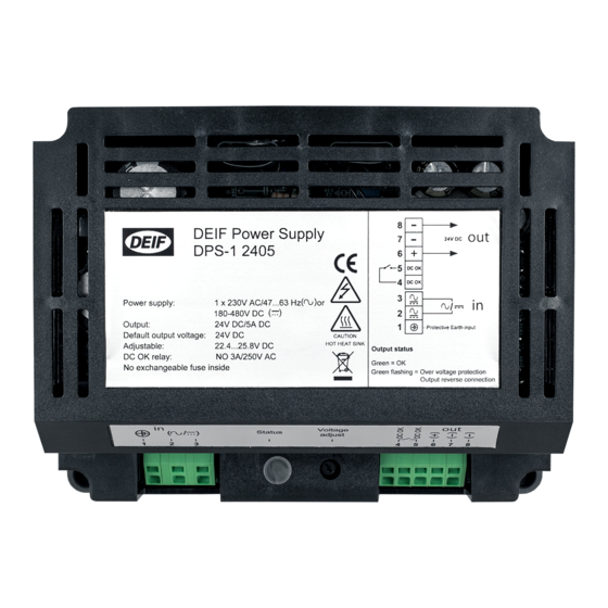
- Page 1 INSTALLATION AND OPERATION INSTRUCTIONS Power supply DPS-1 DEIF A/S ∙ Frisenborgvej 33 ∙ DK-7800 Skive Document no.: 4189360002 Rev.: C Tel.: +45 9614 9614 ∙ Fax: 9614 9615 Date: 2017-06-27 Info@deif.com ∙ www.deifwindpower.com Language: EN-GB...
- Page 2 DPS-1 Installation and operation instructions 4189360002 Rev. C Disclaimer The contents of this document are subject to revision without notice. DEIF A/S shall have no liability for any error or damages of any kind resulting from the use of this document.
-
Page 3: Table Of Contents
DPS-1 Installation and operation instructions 4189360002 Rev. C Introduction Contents Introduction ......................4 Revision history ....................4 Conventions ......................4 Safety precautions ..................... 5 Mechanical work ....................5 Electrical work ....................5 Package content, tools and handling ............... 6 Package content ....................6 3.1.1 Standard package content: ............... -
Page 4: Introduction
DPS-1 Installation and operation instructions 4189360002 Rev. C Introduction 1. Introduction This document describes how to install and operate the DPS-1. The document is intended for persons responsible for integration of the DPS-1 in a pitch system, cabinet design, installation and operation. -
Page 5: Safety Precautions
Observe local regulation when working with electrical components. When the DPS-1 has been powered, there is a risk of stored energy even when the power is disconnected. Wait 5 minutes after the power is disconnected and verify zero energy according to company procedures on the outputs before performing any work. -
Page 6: Package Content, Tools And Handling
3.1 Package content 3.1.1 Standard package content: Quantity Description DPS-1 power supply 3.2 Required tools and accessories The following required tools and accessories are not delivered with the DPS-1. Table 1 Required tools and accessories Tool or accessory Torque Used to Flat Screwdriver 3 mm wide Connect / disconnect wires. - Page 7 DPS-1 Installation and operation instructions 4189360002 Rev. C Package content, tools and handling Sufficient care must be taken to protect the terminal against electrostatic discharges during the installation. Once the unit is installed and connected, these precautions are no longer necessary.
-
Page 8: Mechanical Mounting
DPS-1 Installation and operation instructions 4189360002 Rev. C Mechanical mounting 4. Mechanical mounting Figure 1 DPS-1 2405 mechanical drawing The DPS-1 can be mounted on a 35 mm DIN rail, or by using 4 pcs. 4 mm screws and nuts (chassis mount). www.deifwindpower.com Page 8 of 14... -
Page 9: Din Rail Mounting
Drill six ⌀4 mm holes according to Figure 2 on page and the cabinet drawings for mounting the DPS-1. Use 4 pcs. 4 mm screws and nuts to mount the DPS-1. Torque according to bolt specification. 141 mm Figure 2 DPS-1 2405 drilling drawing www.deifwindpower.com... -
Page 10: Electrical Connections
The following figure shows the connections to the DPS-1. 24V DC DPS-1 DC OK DC OK input - Protective Earth Figure 3 Connection diagram Connect the wires to the DPS-1 according to the wiring diagram. Info Terminals 7 and 8 are internally connected. www.deifwindpower.com Page 10 of 14... -
Page 11: General Recommendations
DPS-1 Installation and operation instructions 4189360002 Rev. C Electrical connections 5.2 General recommendations It is recommended to use ferrules on the wires before connecting it to the connector. The length of ferrule (termination sleeve) is the uninsulated part of the ferrule:... -
Page 12: Operating The Dps-1
DPS-1 Installation and operation instructions 4189360002 Rev. C Operating the DPS-1 6. Operating the DPS-1 The DPS-1 is designed to operate without manual intervention. It is equipped with a visual and electrical indication/alarm that continuously monitors the input and output voltage 6.1 Voltage drop compensation The power supply can be adjusted to compensate the voltage drop in the wiring between the DPS-1 and the load. -
Page 13: Disposal Of The Dps-1
DPS-1 Installation and operation instructions 4189360002 Rev. C Disposal of the DPS-1 7. Disposal of the DPS-1 All products that are marked with the crossed-out wheeled bin (the WEEE symbol) are electrical and electronic equipment (EEE). EEE contains materials, components and substances that can be dangerous and harmful to people's health and to the environment. -
Page 14: Glossary
DPS-1 Installation and operation instructions 4189360002 Rev. C Glossary 8. Glossary 8.1 Terms and abbreviations Light emitting diode Main circuit breaker DEIF Power Supply 8.2 Units Unit Unit Quantity name US name Conversion Alternative Name unit units ����[º����] ampere Current (����[º����] −...
Need help?
Do you have a question about the DPS-1 and is the answer not in the manual?
Questions and answers