Table of Contents
Advertisement
Advertisement
Table of Contents

Summary of Contents for Keymile SUPM1
- Page 1 User Manual SUPM1 supm1_r2b POTS, TDM services XMC20...
- Page 2 Copyright and Confidentiality Copyright in this document vests in KEYMILE. This document contains confi- dential information which is the property of KEYMILE. It must be held in con- fidence by the recipient and may not be used for any purposes except those specifically authorised by contract or otherwise in writing by KEYMILE.
-
Page 3: Table Of Contents
Voice Transmission Specification Signalling Specification Thermal Management Line Test Length of Subscriber Lines Power Consumption Installation Prerequisites Slots and Deployment Scenarios for the SUPM1 Unit Splitters Jumpers Protection Compatibility Connections and Cables © KEYMILE December 2015 page 3 of 94... - Page 4 Commissioning Commissioning of a PSTN Port Operation Unit Optical Indicators Maintenance User Interface Reference Introduction AP: / unit-x: SUPM1 AP: / unit-x / port-y Annex Associated XMC20 Documents Technical Support Product Training © KEYMILE December 2015 page 4 of 94...
- Page 5 SUPM1 unit view Figure 3: XMC25subrack with 19 SUPM1 units and 1 STM14 unit Figure 4: XMC23 subrack with 6 SUPM1 units and 1 SELI8 unit Figure 5: XMC25 subrack with 19 SUPM1 units and 1 VOIP1 unit Figure 6:...
-
Page 6: Preface
Indicates that an action may lead to operating trouble or loss of data. → Possible actions are given. Please note: Shows significant information. → Possible actions are given. © KEYMILE December 2015 page 6 of 94 EN/LZTBU 372 129/1 RC... -
Page 7: Interfaces And Circuit Categories
Preface User Manual SUPM1 Interfaces and Circuit Categories Table 1: Electrical interfaces and circuit categories SUPM1 interface Circuit category according to Max. rating EN 60950-1 Voltage Current Local power supply TNV2 < 72 V < 2.5 A PSTN a/b interface TNV3 <... -
Page 8: Introduction
XMC20. The SUPM1 unit is a 1-slot wide service unit of XMC20. It has 16 PSTN user ports with a telephony bandwidth of 300 Hz to 3.4 kHz. The SUPM1 unit con- verts the analogue voice signal to a 64 kbit/s digital signal (and vice versa). -
Page 9: Unit View
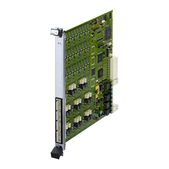
SUPM1 unit view Figure 2 "SUPM1 unit view" shows the SUPM1 unit hardware. On the front plate are two LEDs for the unit- and traffic failure indication and one standard DIN 41 612 based connector for 16 PSTN signals. © KEYMILE December 2015... -
Page 10: Functions And Specifications
Functions and Specifications User Manual SUPM1 Functions and Specifications The SUPM1 unit provides the following functions and conforms to the corre- sponding standards and recommendations (conformance to applicable parts of the standards). Feature Licences Part of the XMC20 functionality is subject to feature licences. For more infor- mation on feature licences please refer to [012] Release Note “XMC20”... - Page 11 Front panel access. One shielded cable is connected to the front panel. It carries all 16 subscriber lines No hardware settable options on the unit. All unit parameters are software settable with the Element Man- ager © KEYMILE December 2015 page 11 of 94 EN/LZTBU 372 129/1 RC...
- Page 12 Main functions and specifications (continued) Feature Rating or standard Release Hot swapping: You can replace a SUPM1 unit without interfering with any other units. No actions on powering, configuration or commissioning need to be taken if you remove/replace a SUPM1 unit Alarm reporting ITU-T X.733 (1992)
-
Page 13: User Ports
User Ports Table 4: User ports Feature Rating or standard Number of user ports per SUPM1 unit Maximum number of subscribers in off-hook per SUPM1 unit, duration infinite © KEYMILE December 2015 page 13 of 94 EN/LZTBU 372 129/1 RC... -
Page 14: Voice Transmission Specification
Q.552; 2.2.1.2; Fig. 1 Impedance unbalance about earth Q.552; 2.2.2; Fig. 2 Relative voice levels Q.552; 2.2.3.1 - Input (Subscriber → SUPM1): -4 … +4 dBr - Output (SUPM1 →Subscriber): -10 … 0 dBr - Selectable in steps of 0.5 dB Tolerances of relative levels Q.552;... - Page 15 ID. Refer to Q.552; 3.1.8.1; Fig. 10: [Ω] [Ω] [nF] Weighted noise Q.552; 3.3.2.1 Total distortion Q.552; 3.3.3; Fig. 14 a, b © KEYMILE December 2015 page 15 of 94 EN/LZTBU 372 129/1 RC...
-
Page 16: Signalling Specification
If a wake up signal, e.g. a polarity reversal, is sent out to initiate CLIP, the terminal will draw a short current pulse which can be interpreted by the SUPM1 as an off-hook event. So the detection time for off-hook has to be increased to prevent this false off-hook detection to ≥... - Page 17 In the MCAS mode of operation, the flash detection times are defined by the CAS. Note: If SUPM1 is in thermal overheat state 1 and a flash impulse is > 200 ms, then this flash impulse will interrupt the call since it is detected as a short but valid on-hook state.
- Page 18 Signalling specification - metering Feature Rating or standard Each subscriber circuit on the SUPM1 unit has its own metering generator. Metering pulses can be sent to the line dur- ing off-hook and up to 25.5 seconds after going on-hook. © KEYMILE December 2015...
- Page 19 Rating or standard Pulsed no battery is supported in the V5CAS mode of opera- tion only. The SUPM1 unit supports two types of pulsed no battery: a-wire and b-wire disconnected (default): An information element (IE) “pulsed no battery” causes a dis- connect of both wires.
- Page 20 An information element (IE) “pulsed no battery” disconnects the a-wire only. The b-wire remains on the –V SUPM1 a-wire b-wire Delay CAS → a/b-wire ≤ 100 ms © KEYMILE December 2015 page 20 of 94 EN/LZTBU 372 129/1 RC...
-
Page 21: Thermal Management
Ongoing calls are not affected. In all other operation modes new calls are possible with- out restriction. Overheat state 2 > 85 °C All ongoing calls are immediately stopped. < 83 °C © KEYMILE December 2015 page 21 of 94 EN/LZTBU 372 129/1 RC... -
Page 22: Line Test
- b, in the range of 300 Hz … 3400 Hz -10, -20, -30, -40 dBm, or “Not used” Capacitance No threshold selectable since no alarm will be generated. The measured value will be displayed. © KEYMILE December 2015 page 22 of 94 EN/LZTBU 372 129/1 RC... - Page 23 User Manual SUPM1 Table 23: Line test - permanent line check Feature Rating or standard a-wire and b-wire short not configurable AC power cross Transversal current Longitudinal current © KEYMILE December 2015 page 23 of 94 EN/LZTBU 372 129/1 RC...
-
Page 24: Length Of Subscriber Lines
- Cable attenuation for voice transmission and/or - Metering pulses. It is highly recommended to use twisted wire pairs in order to minimize the susceptibility to cross talk and induced voltages. © KEYMILE December 2015 page 24 of 94 EN/LZTBU 372 129/1 RC... -
Page 25: Power Consumption
Functions and Specifications User Manual SUPM1 Power Consumption Please note: When operating the SUPM1 unit in a passively cooled subrack the loop cur- rent is limited to 23.5 mA Table 25: Power consumption, V = -48 V [mA] Loop length... - Page 26 User Manual SUPM1 Table 26: Power consumption @ 0.1 Erlang, V = -48 V (continued) [mA] Loop length Off-hook [n] Loop VBAT long 0.24 11.5 long 0.25 12.0 © KEYMILE December 2015 page 26 of 94 EN/LZTBU 372 129/1 RC...
-
Page 27: Installation
Installation User Manual SUPM1 Installation Prerequisites Before installing a SUPM1 unit take care to follow the safety advices as listed in [202] Safety Instructions “Precautions and safety”. Valid combinations of hardware (HW) and embedded software (ESW) ver- sions are given in [012] Release Note “XMC20”. -
Page 28: Slots And Deployment Scenarios For The Supm1 Unit
Slots and Deployment Scenarios for the SUPM1 Unit The SUPM1 unit uses one slot in the XMC20 subrack. In a XMC20, the SUPM1 unit can be operated in any of the following slots: • XMC25: 1 … 10, 12 … 21. -
Page 29: Figure 5: Xmc25 Subrack With 19 Supm1 Units And 1 Voip1 Unit
Installation User Manual SUPM1 XMC25 Slot Slot Slot Network Figure 5: XMC25 subrack with 19 SUPM1 units and 1 VOIP1 unit © KEYMILE December 2015 page 29 of 94 EN/LZTBU 372 129/1 RC... -
Page 30: Splitters
There are no jumpers or any other kind of hardware settable items on the SUPM1 unit. Protection External primary protection (230 V Gas Discharge Tubes) is mandatory for each subscriber line. These protection elements are normally plugged onto the MDF. © KEYMILE December 2015 page 30 of 94 EN/LZTBU 372 129/1 RC... -
Page 31: Compatibility
Installation User Manual SUPM1 Compatibility 4.6.1 XMC20 Units SUPM1 is compatible with any other XMC20 service unit with an ESW release of the current XMC20 system release. Please refer to [012] Release Note “XMC20”. 4.6.2 Previous ESW Revisions The SUPM1 unit with ESW release supm1_r2b was first released for the XMC20 system release R4C. -
Page 32: Connections And Cables
SUPM1 Front Backplane Connector Connectors PSTN port 2 PSTN port 1 Figure 6: Pin-out of the SUPM1 front connectors, front view Table 27: SUPM1 front connector pins PSTN port Connector pin for signal a signal b © KEYMILE December 2015... -
Page 33: En/Lztbu 372 129/1 Rc
Cable 16 Pairs, DIN 41612 to open End An open ended or unterminated cable with 16 pairs is used to connect the 16 interfaces of the SUPM1 unit with the 2-wire interfaces to the MDF. The MDF end of the cable is open ended. - Page 34 The cable route on the cable tray should follow approximately the projection of the unit slot on the cable tray. In the XMC23 and XMC22, cables connecting to the SUPM1 unit or other units should be guided and attached similarly to the way shown in Figure "Side view of the cable tray and the cable in XMC25"...
-
Page 35: Functional Description
XMC20 subrack. V5CAS Mode of Operation Please note: The V5CAS mode of operation is only applicable if the SUPM1 unit is con- nected to the VOIP1 media gateway unit. A PSTN subscriber accesses the SUPM1 unit with three different logical channels: •... -
Page 36: Mercury Cas Modes Of Operation
Voice channel (with inband PSTN signalling ) signalling data voice traffic Figure 9: MCAS routing in XMC20 The SUPM1 supports four different sub modes for the Mercury CAS proto- col: • MCAS direct line • MCAS loop calling PBX •... - Page 37 5.2.4 MCAS PBX Extension A standard telephone set is connected to the SUPM1 unit, and a PBX is con- nected to an exchange side analogue subscriber line service unit. The predefined protocol fixes the CAS bit pattern according to the following table: ©...
- Page 38 CAS bit State downstream upstream Disconnect clear Ground key Call established Off-hook Metering pulse Ringing off Ringing on Circuit free (idle) or busy On-hook Blocking (AIS) Blocking (AIS) © KEYMILE December 2015 page 38 of 94 EN/LZTBU 372 129/1 RC...
-
Page 39: Phone-Exchange Mode Of Operation
User Manual SUPM1 Phone-Exchange Mode of Operation This mode of operation allows you to set the SUPM1 CAS-signalling accord- ing to your needs. Subscribers connected to the SUPM1 can interwork with the exchange side analogue line card TUXA1 or with any third party equipment. - Page 40 Metering pulse function towards the subscriber can be enabled or disa- bled, • Pulse on answer function is disabled, • Polarity reversal function towards the subscriber can be enabled or disa- bled. © KEYMILE December 2015 page 40 of 94 EN/LZTBU 372 129/1 RC...
-
Page 41: Phone-Phone Mode Of Operation
Phone-Phone Auto Ring Down As soon as the calling subscriber (A-subscriber) goes off-hook, the SUPM1 sends the CAS pattern “Off-hook” in upstream direction. The SUPM1 on the receiving side creates the ring back control tone towards the A-subscriber and applies the ringing signal cadence with 2 seconds ringing, followed ©... - Page 42 It is not possible to set two identical CAS patterns for the on-hook and off- hook signalling. Please note: Signalling patterns with all “0” or all “1” are not allowed. © KEYMILE December 2015 page 42 of 94 EN/LZTBU 372 129/1 RC...
-
Page 43: Port States
If any call is not terminated within the next 30 min- utes after the issue of the shutdown command an SHT (shutdown time- out) alarm is raised. © KEYMILE December 2015 page 43 of 94 EN/LZTBU 372 129/1 RC... - Page 44 Only the user ports in the state “unlocked” / “enabled” are really in operation and ready to do calls. In all the other states, the associated user port is either blocked or considered as blocked. © KEYMILE December 2015 page 44 of 94 EN/LZTBU 372 129/1 RC...
-
Page 45: Pstn Maintenance
PSTN Maintenance If for maintenance purposes a subscriber has to be removed from the MDF (main distribution frame) or a SUPM1 unit has to be removed from the XMC20 subrack, this should be done without interrupting ongoing calls. This is accomplished, under the control of the signalling (H.248/MEGACO, SIP or V5), by blocking a user port as soon as an ongoing call is terminated. -
Page 46: Figure 12: Digital Test Loop For Voice Signals
Risk of operating trouble! An ongoing call will be interrupted in direction towards the network. An active test loop activates the MFA (maintenance function active) alarm on the port. © KEYMILE December 2015 page 46 of 94 EN/LZTBU 372 129/1 RC... -
Page 47: Line Impedance Selection
User Manual SUPM1 Line Impedance Selection The hardware of the SUPM1 unit is prepared to comply with many national requirements concerning the line impedance. The line impedance parame- ters can be configured with the element manager. The line impedance is selected from a list according to the national require- ments. -
Page 48: Input And Output Level
Note that the theoretical load capacity of a PCM A-law coded signal is +3.14 dBm0. With a relative level of 0 dBr, the maximum absolute level is therefore 0 dBr + 3.14 dBm0 = 3.14 dBm. © KEYMILE December 2015 page 48 of 94 EN/LZTBU 372 129/1 RC... -
Page 49: Line Feeding
User Manual SUPM1 Line Feeding The analogue a/b-wires of SUPM1 are fed with a line feed current, the loop current. This is the current a subscriber will draw from the interface during off-hook. Since the interface behaves as a constant current source it is possible to define the value of this constant current (= maximum loop current) in the range from 15.0 mA up to 45 mA. -
Page 50: Signalling
On unit level, advanced board parameters, the “Metering Pulse after On Hook” can be configured. This timer defines the time a SUPM1 user port may send out any metering pulses after the subscriber went on-hook. Also the voice path remains transparent during this time. - Page 51 An initial ring or a polarity reversal signal is used as an indica- tion that CLIP will follow as in-band tones. In support of CLIP, the SUPM1 unit opens the voice path to the line upon reception of any PSTN CAS signal in the on-hook state.
-
Page 52: Line Test
A line-test is started either manually (on demand line-test) or automatically in a user-defined interval (cyclic line-test). The SUPM1 checks for each subscriber whether he is busy or idle. If a sub- scriber is busy (off-hook or ringing) the line-test for this particular subscriber is postponed. - Page 53 A reasonable time to start the test is between 2am and 4am since then the traffic is low. Please keep in mind that a line-test for an entire SUPM1 will typically take about 3 minutes and up to 8 minutes in the worst case.
-
Page 54: Figure 15: Test Adapter
− a-wire and b-wire − a-wire and ground − b-wire and ground The test area selection is configured in the SUPM1 unit configuration, on the “Line Test Parameters” tab. The test area selection is valid for cyclic and manual line-tests. - Page 55 The resulting line-test status is displayed as follows: • Requested In this phase the SUPM1 checks the subscriber line for its state (on-hook / off-hook). If a subscriber is on-hook the user port is set to the locked state (V5CAS mode of operation only).
-
Page 56: Figure 16: Finite State Machine For The Line-Test Procedure
Capacitance is untestable, Noise is untestable. Another reason can be that an alarm from a failed line-test has been cleared by the “Reset Line Test Defects” button in the SUPM1 unit status. • Not tested Indicates that this test was not executed and so no test results are availa- ble. - Page 57 Test Defect” button in the SUPM1 unit status. 5.11.5 Permanent line check The permanent line checks are running on the SUPM1 unit as a background process. These line checks do not need any configuration, they run forever automatically. The following parameters are supervised by the permanent line checks: •...
-
Page 58: Thermal Management
SUPM1 5.12 Thermal Management The thermal management system on the SUPM1 prevents any damage of the unit caused by overheating. It is achieved with a temperature sensor. The board controller reads the sensor every second and determines the required action. -
Page 59: Power Management
Power Management The subscriber telephone sets in the PSTN (POTS) application are powered by the access node, i.e. by the SUPM1 unit. The SUPM1 unit is designed to be able to deliver the power to all 16 subscribers simultaneously. If the... -
Page 60: Special Features
5.14.1 Wetting Current SUPM1 allows specific phones to draw a wetting current during the ringing pause. If a wetting current occurs the SUPM1 does not enter the off-hook state. This feature does not need to be configured. © KEYMILE December 2015... -
Page 61: Commissioning
Commissioning User Manual SUPM1 Commissioning In this section, you will find a commissioning example of the SUPM1 unit and the configuration of a port. Please refer to [355] User Manual “ECST” for details on the general GUI aspects, and to [302] User Guide “XMC25/XMC23/XMC22”... - Page 62 MCAS local exchange. The following assumptions and identifiers are used: ‒ The SUPM1 unit is assumed to be plugged in slot 9 of the XMC25. ‒ The SUPM1 unit is assigned. ‒ The port to be configured has the identifier port-1.
- Page 63 Line Test Time-Out = 3.0 h. 9. Execute “Apply”. Configure the line test alarm Proceed as follows: thresholds 1. Navigate to the line test alarm thresholds: AP:/unit-9, Configuration - Line Test Alarm Thresholds. © KEYMILE December 2015 page 63 of 94 EN/LZTBU 372 129/1 RC...
- Page 64 6. Select the priority: Priority = Normal. 7. Enable the cyclic line test for this port: Enable Cyclic Test = true. 8. Disable the DSL adaptation. The SUPM1 does not make use of this parameter: Enable DSL Adaptation = false. 9. Execute “Apply”.
- Page 65 7. Select the A-End CTP: Select the SELI8 unit, port-8/chan-1. 8. Execute “Create”. Result: The bidirectional cross connection between SUPM1 and SELI8 is configured. Activation Proceed as follows: 1. Set the administrative state of the port-1 to up AP:/unit-9/port-1, Main - Admin And Oper Status: Set Administrative Status to “Up”.
-
Page 66: Operation
The operation functions described in this section assume a correctly config- ured and operational SUPM1 unit. Unit Optical Indicators LEDs on the front of the SUPM1 unit are used to indicate to the user the alarm status summary of the unit and of the network traffic signals. XXXXx... -
Page 67: Maintenance
User Manual SUPM1 Maintenance 7.2.1 Inventory Data It is possible to read inventory data from the SUPM1 unit via the ECST with the following access point: AP: /unit-x, Main - Inventory. 7.2.2 Unit ESW Download It is possible to update the embedded software (ESW) of the SUPM1 unit via software download. -
Page 68: User Interface Reference
User Manual SUPM1 User Interface Reference This section gives a complete reference of the managed objects, properties, and commands of the SUPM1 service unit as far as these are not covered in the generic descriptions in [302] User Guide “XMC25/XMC23/XMC22”. - Page 69 Please note: Screenshots presented in this reference are examples and show configura- tions or data that may not correspond to the view you see when managing your XMC20 equipment. © KEYMILE December 2015 page 69 of 94 EN/LZTBU 372 129/1 RC...
-
Page 70: Ap: / Unit-X: Supm1
User Interface Reference User Manual SUPM1 AP: / unit-x: SUPM1 8.2.1 AP: / unit-x, Overview For a description of the − “Overview - Alarms”, and − “Overview - Cross Connections” management functions, please refer to [302] User Guide “XMC25/XMC23/ XMC22”. - Page 71 Blocked Port Line Feed Enabled enabled enabled disabled disabled Metering Pulse Enabled enabled enabled enabled disabled Pulse On Answer Enabled enabled disabled disabled disabled Polarity Reversal Enabled enabled enabled enabled disabled © KEYMILE December 2015 page 71 of 94 EN/LZTBU 372 129/1 RC...
- Page 72 Mercury CAS Loop Calling Mercury CAS is the signalling mode of operation (used in the United Kingdom) between the SUPM1 unit and the P12 transport units in the Mercury CAS Earth Calling application with a Mercury CAS enabled switch. Please refer to section 5.2 Mercury CAS Modes...
- Page 73 Ringing Valid characters are “0”, “1” and “x”. “x” means “don’t care”. The default CAS pattern is “x101”. Note that polarity reversal during ringing is not supported. © KEYMILE December 2015 page 73 of 94 EN/LZTBU 372 129/1 RC...
- Page 74 AP: / unit-x, Configuration - Advanced Unit Parameters Operation Name Parameter Name Range Description / Details This is the time the SUPM1 uses to accept an Advanced Unit CAS AIS Debounc- 0.1 … 1.0 … 25.5 s, AIS on voice and signalling (without interrupting...
- Page 75 AP: / unit-x, Configuration - Advanced Unit Parameters (continued) Operation Name Parameter Name Range Description / Details This timer defines the time a SUPM1 user port Advanced Unit Time-Out 0.0 … 4.0 … 25.5 s, may send out a metering pulse after the sub- Parameters, Meter- step 0.1 s...
- Page 76 Description / Details Alarm threshold resistance between a-wire and Line Test Alarm Not Used b-wire. Thresholds, Resist- 10 kOhm ance/Isolation 20 kOhm 30 kOhm 40 kOhm 50 kOhm 100 kOhm © KEYMILE December 2015 page 76 of 94 EN/LZTBU 372 129/1 RC...
- Page 77 50 V 60 V Alarm threshold foreign DC voltage between b- b-GND Not Used wire and ground. 10 V 20 V 30 V 40 V 50 V 60 V © KEYMILE December 2015 page 77 of 94 EN/LZTBU 372 129/1 RC...
- Page 78 Minor The ESW that is scheduled for installa- Not Available Alarm tion is not available on the unit. Make sure that the ESW is downloaded to the unit. © KEYMILE December 2015 page 78 of 94 EN/LZTBU 372 129/1 RC...
- Page 79 Replace the defective unit. Equipment Malfunction Equipment Critical The SUPM1 controller detects any Alarm anomalies on the unit, e.g. a voltage is missing, a chip does not respond, etc.
- Page 80 “idle” has been detected. Lock all enabled user ports. The user ports are Lock All Ports blocked (locked state) immediately after confir- mation of the warning message. © KEYMILE December 2015 page 80 of 94 EN/LZTBU 372 129/1 RC...
- Page 81 V5CAS mode of operation. b. This command is only available for the V5CAS mode of operation. c. The unit line-test state displays the combined test state of all user ports. © KEYMILE December 2015 page 81 of 94 EN/LZTBU 372 129/1 RC...
-
Page 82: Ap: / Unit-X / Port-Y
Set the IETF administrative status of the port. Administrative Sta- State Down Display of the IETF operational status of the port. Operational Status State Down Testing Unknown Dormant Not Present Lower Layer Down © KEYMILE December 2015 page 82 of 94 EN/LZTBU 372 129/1 RC... - Page 83 0.5 High priority subscribers are able to do new Priority Normal calls also when the SUPM1 unit is in over- heat state 1 or in power state 2. Refer to section 5.12 Thermal Management High (on page 58) and to section 5.13 Power Man-...
- Page 84 CTP Configuration Layer Rate P0_nc P0_nc, i.e. n x 64 kbit/s. The layer rate property of a SUPM1 port is fixed to P0_nc. Layer rate of the connection termination point is P12, i.e. 2048 kbit/s. Number of timeslots in case of P0_nc. The pos- 0 …...
- Page 85 Affecting Severity Equipment Malfunction Equipment Critical This alarm shows that a subscriber cir- Alarm cuit on the SUPM1 is out of order. Such a fault is detected during an internal HW check. Overload Equipment Major This alarm occurs if a subscriber line...
- Page 86 Hazardous voltages. Risk of electric shock! WARNING With an active FRV alarm there is a risk of hazardous voltages! Mains volt- age of 115VAC or 230VAC is a danger to life. © KEYMILE December 2015 page 86 of 94 EN/LZTBU 372 129/1 RC...
- Page 87 For the a description of the general aspects of the performance management (PM) functions, please refer to [302] User Guide “XMC25/XMC23/XMC22”. The following counter group is available for the SUPM1 ports: • “Protection” group, see section 8.3.5.1 AP: / unit-x / port-y, Performance...
- Page 88 The actual user port status is controlled by the local exchange, the subscriber or the management system. Please refer to section 5.5 Port States (on page 43). b. This command is only available for the V5CAS mode of operation. © KEYMILE December 2015 page 88 of 94 EN/LZTBU 372 129/1 RC...
- Page 89 52) Line-test description. Results - Test Foreign DC Voltage a-GND Description Foreign DC Voltage b-GND Foreign DC Voltage a-b Foreign AC Voltage a-GND Foreign AC Voltage b-GND © KEYMILE December 2015 page 89 of 94 EN/LZTBU 372 129/1 RC...
- Page 90 Activate the loopback of the digital voice sig- Enable test loop nal towards the network. Deactivate the loopback of the digital voice Disable test loop signal towards the network. © KEYMILE December 2015 page 90 of 94 EN/LZTBU 372 129/1 RC...
- Page 91 The trail from the a-end working remote CTP has Active Trail Working been selected. The trail from the a-end protecting remote CTP Protecting has been selected. There is no active trail. Not Available © KEYMILE December 2015 page 91 of 94 EN/LZTBU 372 129/1 RC...
- Page 92 Prefer the trail from the a-end protecting remote Manual Protecting CTP. Use this trail only if the fault status is not worse than the fault status of the working trail. © KEYMILE December 2015 page 92 of 94 EN/LZTBU 372 129/1 RC...
-
Page 93: Annex
[340] Quick Guide “TDM Services over PDH/SDH” [447] User Manual “COGE5, COGE5-F co5ne_r2, co5un_r2” [410] User Manual “SELI8 seli8_r5” [452] User Manual “VOIP1 voip1_r2” [458] User Manual “FIL16” © KEYMILE December 2015 page 93 of 94 EN/LZTBU 372 129/1 RC... -
Page 94: Keymile December 2015
Please refer to the KEYMILE Extranet (via http://www.keymile.com) for sup- port contact information. Product Training Training courses are available for a wide range of KEYMILE products and applications. For contact information, course descriptions, locations and dates, go to the Website: http://www.keymile.com, then search for “product training”.
Need help?
Do you have a question about the SUPM1 and is the answer not in the manual?
Questions and answers