
Summary of Contents for Valfonta S3
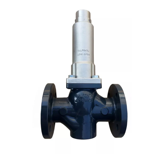
- Page 1 VALFONTA INSTRUCTIONS: OPERATION AND INSTALLATION PRESSURE RELIEF VALVE SPRINGLOADED MODEL Pressure Relief Valve S3 - Operation and Installation - 1 - manual S3-17A-ENG February 2017...
-
Page 2: Table Of Contents
VALFONTA INDEX PAGE IDENTIFICATION PLATE LEGEND MAIN FEATURES OPERATION SCHEME ASSEMBLY POSSIBLE TROUBLESHOOTING INSTALLATION DRAWINGS RECEIPT ON SITE Pressure Relief Valve S3 - Operation and Installation - 2 - manual S3-17A-ENG February 2017... -
Page 3: Identification Plate Legend
CE marked is required in accordance with PED 2014/68/UE b) CE marked is NOT required in accordance with PED 2014/68/UE SERIAL N. VALVE IDENTIFICATION NUMBER. VALFONTA WILL NEEDS THIS NUMBER FOR SPARE PARTS OR COMMENTS RESPECT OF THIS VALVE. MOD. - Page 4 IIC Safety construction protection mode for substances C IIIC IIIC Tx / TxºC Termal class according fluid temp. used Number of certification from ExNB (LOM) Pressure Relief Valve S3 - Operation and Installation - 4 - manual S3-17A-ENG February 2017...
-
Page 5: Main Features
Handwheel regulation, specials gaskets, Super Duplex construction, bronze construction, … Approvals Quality system ISO 9001, Pressure equipment Directive according 2014/68/UE and Atex Directive according 2014/34/UE (file pending to include). Pressure Relief Valve S3 - Operation and Installation - 5 - manual S3-17A-ENG February 2017... - Page 6 Ti >135ºC 100ºC Ti >100ºC 85ºC Ti >85ºC Class II (combustible dust) T(x) ≤ 2/3 MIT cloud T(x)≤ 5 mm MIT – 75 K layer Pressure Relief Valve S3 - Operation and Installation - 6 - manual S3-17A-ENG February 2017...
-
Page 7: Scheme
This device must be installed by specialized personnel with knowledge and experience. They must know about the current regulations in order to judge the risks that may involve this work. Pressure Relief Valve S3 - Operation and Installation - 7 - manual S3-17A-ENG... -
Page 8: Assembly
Recommended installation position in horizontal pipeline. The pressure gauge located on the upstream pressure side allows the adjusted set point to be monitored. Pressure Relief Valve S3 - Operation and Installation - 8 - manual S3-17A-ENG February 2017... - Page 9 Before any maintenance, ensure the valve is depressurised and clear of media, and isolate it both upstream and downstream. Be sure the temperature isn’t dangerous. IMPORTANT! Use only genuine parts or recommended by VALFONTA, SL Pressure Relief Valve S3 - Operation and Installation...
-
Page 10: Possible Troubleshooting
Refer to technical sheet HT-101 EPDM, FPM PTFE+GR PEEK Max. permissible temperature: plug 80ºC 150ºC 220ºC 250ºC Max. permissible temperature: Packing PTFE+GRAPHITE UP TO 220ºC Pressure Relief Valve S3 - Operation and Installation - 10 - manual S3-17A-ENG February 2017... -
Page 11: Installation Drawings
(mm) ○ ○ (inches) 7,76” 9,25” 10,51” 11,5” 12,50” 14,49” (sealing cap) (mm) (Handwheel) (mm) Weight (kg) ○ Available under request Flanged type Threaded type Pressure Relief Valve S3 - Operation and Installation - 11 - manual S3-17A-ENG February 2017... -
Page 12: Receipt On Site
Mechanical Verification Check all moving parts of the apparatus, as well as screws and other elements fulfill their mission. IMPORTANT! If is observed abnormality during these guidelines reception, contact urgently VALFONTA to clarify responsibilities and put the devices in correct status.
Need help?
Do you have a question about the S3 and is the answer not in the manual?
Questions and answers