Table of Contents
Advertisement
Advertisement
Table of Contents

Subscribe to Our Youtube Channel
Related Manuals for SolarMax MaxWeb xp

Summary of Contents for SolarMax MaxWeb xp
- Page 1 MaxWeb xp Installation instructions...
-
Page 2: Table Of Contents
Configuration of MaxWeb xp � � � � � � � � � � � � � � � � � � � � � � � � � � � � � � � � � � � � �... - Page 3 Opening the MaxWeb Portal ........32 Opening the MaxWeb xp user interface ......32 Expansion Port �...
-
Page 4: About This Installation Manual
1310-2 MaxWeb xp GPRS 1310-4 1�2 Target group The installation of the MaxWeb xp may only be carried out by trained, skilled electri- cians (e.g. electricians, electric systems technicians, electrical mechanics, industrial electronics technicians). 1�3 Where to keep this manual The system operator must ensure that this instruction manual is available to those responsible for the power plant at all times. -
Page 5: Safety
Safety 2�1 Appropriate use The web-based MaxWeb xp data logger is solely for the logging of device and plant data within a MaxComm communications network. MaxWeb xp provides the following basic functions: Internet-capable data logger for system communication via standard Internet ■... -
Page 6: Description
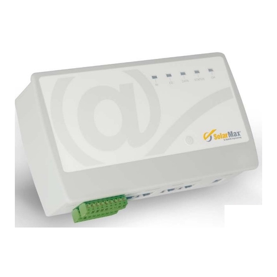
The five LEDs at the top of the casing indicate the operational status. MaxWeb xp Ethernet DATA STATUS On: electrical connection Flashes during data Lights up when function to the network is active. reception from the MaxWeb xp is running. function Off: no connection. devices. -
Page 7: Installation
Crossover Ethernet connection cable (short, red) 4�3 Siting Please note the following when siting your MaxWeb xp: MaxWeb xp meets the requirements of protection class IP20 and is therefore only ■ ■ suitable for installation in dry, clean spaces. For outdoor installation or operation... -
Page 8: Device Installation
35mm top-hat rail. Installation of the MaxComm network 5�1 Connection options Up to 75 devices with a MaxComm interface can be connected to your MaxWeb xp data logger. Device Purpose SolarMax inverters... -
Page 9: Wiring
Other topologies are not recommended owing to the high data volumes and corresponding high connection costs. Connection option with bridge between the “Modem ISDN” and “Ethernet” connec- ■ ■ tions (the bridge is included in the delivery package): MaxWeb xp GPRS Modem Ethernet RS485 RS485... -
Page 10: Addressing
5�3 Addressing For MaxWeb xp to be able to detect connected devices, you must assign an unambiguous device address to every device. Please note that each device address must be used once only. You will find instructions for setting the address in the product description of the... -
Page 11: Ethernet Connection
All inverters and devices with an Ethernet interface can be operated within a LAN network together with MaxWeb xp. The inverters connected to MaxWeb xp by means of the Ethernet interface assume the gateway function for the other devices. Behind the gateway inverters the MaxComm net- work consists of RS485 connections. -
Page 12: Power Supply
The power supply should be independent of the inverter AC feed cable. If ■ ■ this is not the case, the MaxWeb xp will be disconnected from the power supply when the inverters disconnect from the mains. Use an uninterruptible 230 VAC power supply for the plug-in mains unit. -
Page 13: Configuration Of Maxweb
MaxWeb xp. Then connect the plug-in mains unit to the power supply. As soon as the power supply is connected, MaxWeb xp starts and the status LED comes on. After approx. 30 seconds the device is accessible via the web browser. -
Page 14: Modifying Your Network Settings
Just in case, write down the values you have set before you reboot MaxWeb xp. 1. Connect MaxWeb xp directly to the Ethernet interface of your PC using the red cross- over cable. 2. From Windows XP open the menu Control panel > Settings > Network Connections >... -
Page 15: Maxweb Xp Ethernet
6�4�1 Recommendations for the SIM card To use MaxWeb xp via GPRS you need a SIM card with GPRS data service. The services and tariffs offered by different providers vary widely. For this reason only general instruc- tions can be given at this point. -
Page 16: Installation Instructions For The Maxweb Xp Gprs
Leave the SD card in its base. 6�4�3 GPRS configuration 1. Connect the the Ethernet socket of your PC with the Modem socket of the MaxWeb xp using the red crossover cable. Note To access MaxWeb xp the network connection of your PC must be appropri- ately configured (see Section 6.2.3). - Page 17 7. Switch MaxWeb xp off (see Section 6.1). Installing the SIM card 8. Fully disconnect the MaxWeb xp from the power supply by pulling the plug-in mains unit from the socket. 9. Release the four screws under the edge of the cover and lift it off.
- Page 18 15. Enter “http://192.168.1.234” in the web browser. The MaxWeb xp login screen will appear. 16. Enter “admin” as user name and “solarmax.com” as password and click “OK” in order to log into MaxWeb xp. The start-up screen of the MaxWeb Wizard appears. 17. Continue with the configuration in accordance with Section 6.5.
-
Page 19: Configuration Using Maxweb Wizard
The Wizard helps you configure your MaxWeb xp correctly. The configuration consists of 13 steps. You can complete all the steps in the Wizard only if MaxWeb xp is connected to the Internet. The other network subscribers must also be connected via an RS 485 or Eth- ernet interface and configured with the correct address. -
Page 20: Connection Test
If you connected MaxWeb xp via the red crossover cable directly to your PC, use the grey cable to connect MaxWeb xp to your local network. Your PC must also be connected to the same network. Then enter the previously defined IP address of MaxWeb xp in your web browser and log in again. - Page 21 1. Log out of MaxWeb xp. 2. Remove the red Ethernet cable from the socket labelled Ethernet and connect the sockets labelled Modem and Ethernet on the MaxWeb xp with the red, short Ethernet cable. 3. Wait roughly 3 minutes, remove the short Ethernet cable, Connect the long, red Eth- ernet cable to your PC.
-
Page 22: Contract Data
6�5�4 Contract data Select the following settings: Option Setting Description Replacement device The data logger has been replaced. Enter the replace- ment ID. You can obtain the replacement ID from the MaxWeb Portal (path: plant administration/data logger/ processing data logger/replacement number). It is not a replacement device. -
Page 23: Plant Settings
6�5�5 Plant settings Enter a name for your plant for the MaxWeb Portal and the local time zone. Click OK to save your settings. 6�5�6 Device communications settings The communications modus to the inverters can be selected here. If you have selected RS485, no further entries are necessary and you can click NEXT to proceed to the next step. -
Page 24: Find Devices
MaxWeb Portal before starting a device search. Click on START. MaxWeb xp begins to search the whole address range for installed devices. You can interrupt the search once you are certain that above the current search address there are no further devices. -
Page 25: Device Settings
Note If MaxWeb xp does not detect or display all devices, the internet browser may be configured incorrectly (see Section 7.2). 6�5�8 Device settings Here you can see the currently installed devices. You can adapt the names, the installed capacity and the serial numbers. -
Page 26: Energy Values
6�5�9 Energy values The energy value logger records the energy values of the selected devices (kWh day, kWh month, kWh year and kWh Total) at a specified time on each day. By clicking on the “Active” box you can switch the logger on or off. Select the devices to be logged from the “Device selection”... -
Page 27: Time Values
6�5�10 Time values The time value logger uses selected values to generate snapshots for a settable interval. By clicking on the “Active” box you can switch the logger on or off. Enter the start and stop times to define the period for which data is logged. Enter the Interval to set how frequently data is recorded. - Page 28 Measured value Description Unit Voltage Uac L1 AC output voltage, phase 1 Voltage Uac L2 AC output voltage, phase 2 Voltage Uac L3 AC output voltage, phase 3 Voltage Udc DC input voltage Voltage Udc1 … DC input voltage, tracker 1 … tracker 12 Voltage Udc12 Voltage Ugnd Voltage of the PV generator in comparison with the...
-
Page 29: Alarming
6�5�11 Alarming Define up to 3 email and SMS recipients of alarm messages: Parameter Description Email Email address Telephone number for SMS in international format, e.g. ++491719999999 Language Language of alarm messages (DE, EN, FR, ES, IT) Alarm level The recipient will receive alarm messages up to the specified alarm level. The operating status of the inverter is "Failure"... -
Page 30: Energy Comparison
6�5�12 Energy comparison The relative daily yields of all inverters are compared. The relative daily yield is calculated from the installed capacity and the daily yield. Hence the importance of correctly setting the installed capacities for each device. If the relative yield of one or more inverters falls shorter of the mean value for all the inverters than the specified tolerance an Alarm 3 alarm is sent. -
Page 31: Date/Time Settings
Enter the current date and local time. When you save the entries by clicking OK they become the system date/time for MaxWeb xp. 6�5�14 Finishing the MaxWeb Wizard The successful configuration is confirmed. Click FINISH and the standard MaxWeb xp interface is displayed. Register for access to the MaxWeb Portal (see Section 6.6). -
Page 32: Maxweb Portal Registration
2. In the “Basic settings” menu, click on “General”. 3. Enter a valid email address in the “MaxWeb Portal” field. 4. Click “OK”. As soon as MaxWeb xp sends the first data set to the MaxWeb Portal, you will receive your acces data via email. 6�7... -
Page 33: Access To The Pv Plant
4. Enter your registration details. The “Overview” tab will be displayed. Browser compatibility Certain elements of the MaxWeb xp interface require JavaScript support. The JavaScript support must be activated in the web browser. MaxWeb xp was tested using the following web browsers: Firefox from version 3 ■... - Page 34 Useful information for Internet Explorer 6 and 7 The following settings are required for displaying the current system overview, device installation and device monitor: 1. In Internet Explorer open the menu Tools / Internet Options / General 2. Click on “Settings” under “Temporary Internet files” (Internet Explorer 7: “Browsing history”).
-
Page 35: Expansion Port
Please note the following when connecting sensors for irradiance und/or temperature measurement to the expansion port: The distance between the sensor and MaxWeb xp should not exceed 50 m. For larger ■ ■ distances the auxiliary MaxMeteo module is required. - Page 36 A combined irradiance and cell temperature sensor (Si-420TC-T) with preconfigured ■ ■ measuring inputs is available from Sputnik Engineering. Connect the sensor to the expansion port as follows: Signal Wire colour Expansion port terminal black Irradiance orange Cell temperature brown For other sensors adjust the measuring input parameters as required.
-
Page 37: Configuration
Configure the expansion port for your data logger in the menu Devices - External devices. Further information can be found in the electronic help file for your MaxWeb xp. 1. Activate the necessary sensors in MaxWeb xp under Devices / External devices, and enter for each one the offset and the gradient as described above. -
Page 38: Terminal Assignment
8�5 Terminal assignment Terminal Function Signal/Limit values Connection schema External alarm inputs GND for A und B for each input – open: 15 V Alarm input A – closed: < 10 mA Alarm input B Status signalling contact Reference maximum switching capacity: Closes to C in the event of –... -
Page 39: Troubleshooting
■ ■ Installation location ■ ■ Information on the present failure (status message, etc.) ■ ■ Availability The contact details of the SolarMax Service Center can be found overleaf. Sputnik Engineering AG Länggasse 85 CH-2504 Biel-Bienne 10 Technical data MaxWeb xp... -
Page 40: 11 Disposal
11 Disposal Dispose of the data logger in compliance with the disposal regulations for electrical equip- ment applicable at the place of installation. 12 Warranty Sputnik Engineering AG (hereafter SPUTNIK) guarantees full function and lack of defects of its technical devices for a warranty period as specified below for each type of device. Such warranty period can be extended by means of a warranty extension, subject to the conditions named below. - Page 41 Any further claims, especially claims for compensation of damages resulting directly or indirectly from the defect or claims for replacement of further costs in connection with the installation and removal of devices or claims for loss of profits are not covered by this warranty. 3�...
- Page 42 In case these terms on the handling of warranty cases are not respected, SPUTNIK may refuse its warranty performances. 7� Suspension of Warranty Sputnik reserves its right to suspend this manufacturer’s warranty temporarily or definitely in case a specific installation does not allow a correct functioning of the inverters (e.g. in case of one of the circumstances listed in cipher 5).
- Page 43 Sputnik Engineering AG Länggasse 85 CH-2504 Biel/Bienne Tel: +41 32 545 56 00 Fax: +41 32 346 56 09 E-Mail: info@solarmax.com © Sputnik Engineering AG 2013...
- Page 44 SolarMax Service Center: hotline@solarmax.com www.solarmax.com/service...
Need help?
Do you have a question about the MaxWeb xp and is the answer not in the manual?
Questions and answers