Table of Contents

Summary of Contents for Masibus Automation VMS4SE
-
Page 1: User Manual
USER MANUAL VMS4SE VIBRATION MONITOR Masibus Automation & Instrumentation Pvt. Ltd. B/30, GIDC Electronics Estate, Sector-25, Gandhinagar-382044, Gujarat, India +91 79 23287275-79 +91 79 23287281-82 Email: support@masibus.com Web: www.masibus.com... -
Page 2: Table Of Contents
1.1 Product Ordering Code ......................8 2. INSTALLATION ..........................9 2.1 Safety Precautions in Installation ..................... 9 2.2 Mounting of VMS4SE ......................10 2.3 Maintenance and Inspection ....................11 3. HARDWARE SPECIFICATION ...................... 13 3.1 Vibration Input Specification ..................... 13 3.1.1 Input Specification(Optional)* .................... -
Page 3: List Of Tables
VMS4SE(Vibration Monitor) REF NO: mVMA/om/101 Issue No: 01 9. CALIBRATION PROCEDURE ....................... 61 10. MODBUS COMMUNICATION DETAIL ..................63 10.1 Overview ..........................63 10.2 Exception Responses ......................64 10.3 Modbus Addresses ....................... 65 11. TROUBLESHOOTING ........................83 APPENDIX – A PV STATUS DURING SENSOR BURN OUT CONDITIONS ........84 APPENDIX –... - Page 4 VMS4SE(Vibration Monitor) REF NO: mVMA/om/101 Issue No: 01 Table 33 Alarm 1 and Alarm 2 Maintained Alarm Logic ............... 58 Table 34 Control Operation (Optional) ....................59 Table 35 Error Messages and its Description ..................60 Table 36 Group Calibration Detail ......................61 Table 37 Modbus Communication frame format ...................
-
Page 5: List Of Figures
Figure 13 Analog Output Cable Connection ..................29 Figure 14 Communication Cable Connection ..................33 Figure 15 Profibus Configuration Cable ....................34 Figure 16 Functional Block Diagram of VMS4SE ................. 35 Figure 17 Program Mode Flow diagram ....................36 Figure 18 Configuration Mode Flow diagram ..................37 Figure 19 Configuration Mode Flow diagram .................. -
Page 6: Safety Precautions
VMS4SE(Vibration Monitor) REF NO: mVMA/om/101 Issue No: 01 SAFETY PRECAUTIONS The product and the instruction manual describe important information to prevent possible harm to users and damage to the property and to use the product safely. Understand the following description (signs and symbols), read the text and observe Descriptions. -
Page 7: Introduction
Please read instructions carefully before altering any programming or configuration information. The VMS4SE module operates independently and can also be connected to a data Highway for remote systems communication functions through a personal computer or a distributed control system (DCS) using RS 485 or Ethernet communication. -
Page 8: Product Ordering Code
Issue No: 01 1.1 Product Ordering Code The VMS4SE Vibration Monitor unit has a nameplate affixed to the one side of the enclosure. Check the model and suffix codes inscribed on the nameplate to confirm that the product received is that which was ordered. -
Page 9: Installation
To connect the protective conductor terminal to earth, complete these steps: 1) Use a spade lug to make contact with the metal surface of the VMS4SE. 2) Use a green and yellow wire to reliably earth the protective conductor terminal. Wire gauge must be no thinner than the current-carrying wire in the product‟s mains supply. -
Page 10: Mounting Of Vms4Se
VMS4SE(Vibration Monitor) REF NO: mVMA/om/101 Issue No: 01 2.2 Mounting of VMS4SE Mounting Method : Panel Mounting External Dimensions and Panel Cut Out Dimensions : Unit: mm Figure 1 Panel Cutout Dimensions User Manual... -
Page 11: Maintenance And Inspection
VMS4SE(Vibration Monitor) REF NO: mVMA/om/101 Issue No: 01 Side View and Top View Figure 2 Side View and TOP view Note : - 1) AOC (Analog Output Cable) can be used in place of OCC(Open Collector Cable) 2) VIC (Vibration Input Cable) can be used in place of AIC (Analog Input Cable) 2.3 Maintenance and Inspection... - Page 12 VMS4SE(Vibration Monitor) REF NO: mVMA/om/101 Issue No: 01 Check the front panel LEDs: Check the Control LED display Digital Output – Open collector (DO-OC). The corresponding LED illuminates when the external input signal (Analog Input) is above Control Set point.
-
Page 13: Hardware Specification
VMS4SE(Vibration Monitor) REF NO: mVMA/om/101 Issue No: 01 3. HARDWARE SPECIFICATION 3.1 Vibration Input Specification NO. OF CHANNEL 4,8 & 12 ACCELEROMETER INPUT Remote ICP piezoelectric Accelerometer Sensitivity: 100 mV/g ±10% Dynamic range: 80 g pk INPUT TYPE As specified in Table 4... -
Page 14: Output Specification
VMS4SE(Vibration Monitor) REF NO: mVMA/om/101 Issue No: 01 450 to 1800C 0 to 1750C + 0.1% of instrument range + 1 digit 1C 0 to 1750C -200 to 1300°C RTD(PT100) -199.9 to 850.0C CU53 -210.0 to 210.0°C + 0.1% of instrument range + 1 digit 0.1C... -
Page 15: Communication Specification
VMS4SE(Vibration Monitor) REF NO: mVMA/om/101 Issue No: 01 SOFTWARE MEMORY Non volatile, restored after power loss 3.4 Communication Specification NO. OF COMMUNICATION 2-RS485(COM-1 and COM-2) . COM2 is Optional PORT COMMUNICATION TYPE Half duplex/Asynchronous COMMUNICATION MODBUS RTU (Baud rate and Parity bit are selectable). All PROTOCOL parameters are Configurable through MODBUS Protocol. -
Page 16: Display Specification
VMS4SE(Vibration Monitor) REF NO: mVMA/om/101 Issue No: 01 FAT32 USB fetched data file format .xls (only) Full Data Fetch (For Periodic and Event Records) Fetch data by time(approximately) (For Periodic Records USB data retrieving option only) Note : * - With USB port, CE marking is not applicable/valid. -
Page 17: Construction, Installation, And Wiring Specification
VMS4SE(Vibration Monitor) REF NO: mVMA/om/101 Issue No: 01 3.12 Construction, Installation, and Wiring Specification MATERIAL Aluminium extrusion CONSTRUCTION Panel Mount Top and Bottom mounting clamps (1 each) CASE COLOR Clear Anodized WEIGHT 1.25 KG ENCLOSURE DIMENSION 72mm (W) X 144mm (H) X 165mm (D) PANEL CUTOUT 68.5mm (W) x 137mm (H) -
Page 18: Front And Rear Panel Diagram
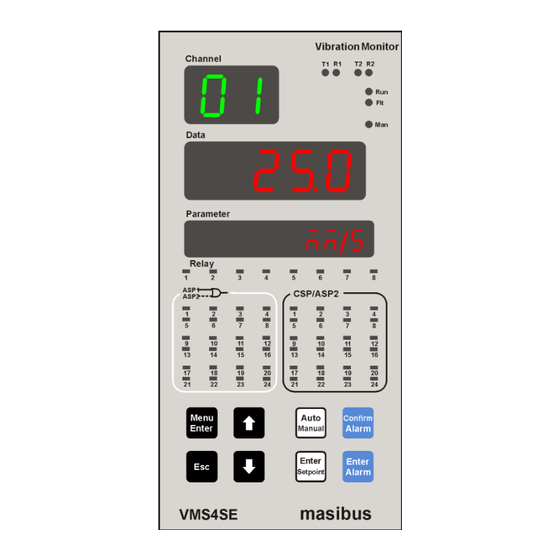
VMS4SE(Vibration Monitor) REF NO: mVMA/om/101 Issue No: 01 4. FRONT AND REAR PANEL DIAGRAM 4.1 Front Panel Diagram Figure 3 Front Panel Diagram Name of Part Indication on Front Panel Channel Display Channel Data Display Data Parameter Display Parameter COM-1 RS485 slave indicator LED... -
Page 19: Rear Panel Diagram
VMS4SE(Vibration Monitor) REF NO: mVMA/om/101 Issue No: 01 It is used in decrementing value when run mode and other DECREMENT KEY modes. It is also used for shifting a digit while editing of numeric value.(When user wants to edit numeric value, Decrement key will work as shift key) It allows user to toggle between Auto Channel Display mode –... -
Page 20: Figure 6 Rear Panel Diagram With Ac Supply
VMS4SE(Vibration Monitor) REF NO: mVMA/om/101 Issue No: 01 Rear Panel Diagram for Profibus Connectivity (Optional): Figure 6 Rear Panel Diagram with AC Supply Figure 7 Rear Panel Diagram with DC Supply For Profibus Connectivity for Profibus Connectivity User Manual... -
Page 21: Connection Diagram
VMS4SE(Vibration Monitor) REF NO: mVMA/om/101 Issue No: 01 5. CONNECTION DIAGRAM 5.1 Connection Terminal Details DO – RL Relay Terminals: 16 Pre-Feb. Cable Power Supply: Live (L/+), Neutral(N/-) and Earth ( Pre-Feb. Cable AI-1,2 and 3 Analog Input: 72 or AI-1 Vibration Input: 4 and AI-2 Analog Input: 8 ... - Page 22 Ground the device. Otherwise, it may cause an electric shock or fire. Connect the protective conductor terminal to earth, Use a spade lug to make contact with the metal surface of the VMS4SE. All wiring must confirm to appropriate standards of good practice and local codes and regulations.
-
Page 23: Cable Details
VMS4SE(Vibration Monitor) REF NO: mVMA/om/101 Issue No: 01 5.2 Cable Details Digital Output – Relay Cable Details: Figure 9 Relay Cable Connection (Three Output Terminals) User Manual... -
Page 24: Table 7 Pin Details Of Relay Cable (Three Output Terminals)
VMS4SE(Vibration Monitor) REF NO: mVMA/om/101 Issue No: 01 Table 6 Pin Details of Relay Cable (Three Output Terminals) DIGITAL OUTPUT - RELAY ( DO - RL ) (Three Output Terminals) Sr. No. Connector Pin No. Pin Detail Ferrule No. NOT CONNECTED... -
Page 25: Figure 11 Open Collector Cable Connection
VMS4SE(Vibration Monitor) REF NO: mVMA/om/101 Issue No: 01 Digital Output – Open Collector Cable Details: Figure 10 Open Collector Cable Connection User Manual... -
Page 26: Table 8 Pin Details Of Open Collector Cable
VMS4SE(Vibration Monitor) REF NO: mVMA/om/101 Issue No: 01 Table 7 Pin Details of Open Collector Cable DIGITAL OUTPUT - OPEN COLLECTOR ( DO - OC ) Connector Pin Sr. No. Pin Detail Ferrule No. GROUND DO10 DO11 DO12 DO13 DO14... -
Page 27: Figure 12 Analog Input Cable Connection
VMS4SE(Vibration Monitor) REF NO: mVMA/om/101 Issue No: 01 Analog Input Cable Details: Figure 11 Analog Input Cable Connection User Manual... -
Page 28: Table 9 Pin Details Of Analog Input Cable
VMS4SE(Vibration Monitor) REF NO: mVMA/om/101 Issue No: 01 Table 8 Pin Details of Analog Input Cable ANALOG INPUT ( AI-1 , AI-2 , AI-3 ) Connector Pin Sr. No. Pin Detail Ferrule No. 1a/+ 1B/- 2a/+ 2B/- 3a/+ 3B/- 4a/+... -
Page 29: Figure 13 Analog Output Cable Connection
VMS4SE(Vibration Monitor) REF NO: mVMA/om/101 Issue No: 01 Analog Output Cable Details: Figure 12 Analog Output Cable Connection User Manual... -
Page 30: Table 10 Pin Details Of Analog Output Cable
VMS4SE(Vibration Monitor) REF NO: mVMA/om/101 Issue No: 01 Table 9 Pin Details of Analog Output Cable ANALOG OUTPUT ( AO ) Sr. No. Connector Pin No. Pin Detail Ferrule No. AO 1 + AO 1 - AO 2 + AO 2 -... - Page 31 VMS4SE(Vibration Monitor) REF NO: mVMA/om/101 Issue No: 01 Vibration Input Cable Details: User Manual...
-
Page 32: Table 12 Pin Details Of Vibration Input Cable
VMS4SE(Vibration Monitor) REF NO: mVMA/om/101 Issue No: 01 Table 10 Pin Details of Vibration Input Cable VIBRATION INPUT CABLE ( AO ) Connector Pin No. Pin Detail Ferrule No. Channel 1 + Channel 1 - Channel 1 Buffer Output Channel 2 +... -
Page 33: Figure 14 Communication Cable Connection
VMS4SE(Vibration Monitor) REF NO: mVMA/om/101 Issue No: 01 Communication Cable Details: Figure 13 Communication Cable Connection RS485 Cabling Methodology should be Shielded single twisted pair cable. RS485 is designed to be used with a single twisted pair cable. It would reduce noise induced through ground potential differences. -
Page 34: Table 13 Pin Details For Profibus Communication (Db 9 Female At Instrument Side)
VMS4SE(Vibration Monitor) REF NO: mVMA/om/101 Issue No: 01 PROFIBUS Connection Detail (DB 9 FEMALE at Instrument Side) Table 11 Pin Details for Profibus Communication (DB 9 Female at Instrument Side) Pin No. Signals Description DATA AND POWER SIGNALS RxD/TxD-P Receive/Transmit data; line B... -
Page 35: Brief Operating Procedure
VMS4SE . On LED status, user can set Alarm 1 Status – Alarm 2 Status or Alarm Status – Control Output Status or Alarm Status – Open Collector Status. -
Page 36: Menu Layout
VMS4SE(Vibration Monitor) REF NO: mVMA/om/101 Issue No: 01 7. MENU LAYOUT 7.1 Parameter Flow Diagram Figure 16 Program Mode Flow diagram User Manual... -
Page 37: Figure 18 Configuration Mode Flow Diagram
VMS4SE(Vibration Monitor) REF NO: mVMA/om/101 Issue No: 01 Figure 17 Configuration Mode Flow diagram User Manual... -
Page 38: Figure 19 Configuration Mode Flow Diagram
VMS4SE(Vibration Monitor) REF NO: mVMA/om/101 Issue No: 01 Figure 18 Configuration Mode Flow diagram User Manual... -
Page 39: Menu Parameters- In Detail
VMS4SE(Vibration Monitor) REF NO: mVMA/om/101 Issue No: 01 Figure 19 Calibration Mode and Security Mode Flow diagram 7.2 Menu Parameters- In Detail Run Mode : Following parameters can view or change during run time. Immediately after powering, unit will run in Auto Mode. In auto mode channel will scan automatically according to scan time selection (1-250 second). -
Page 40: Table 14 Program Mode Parameters
VMS4SE(Vibration Monitor) REF NO: mVMA/om/101 Issue No: 01 By pressing Auto / Manual Key after going into the Manual Mode unit comes back to run mode. By pressing Enter Alarm Key in run mode, the menu goes into the settings of alarm set point value. -
Page 41: Table 15 Configuration Mode Parameters
VMS4SE(Vibration Monitor) REF NO: mVMA/om/101 Issue No: 01 a.s.Hy Prog Alarm Set Alarm Set Point Hysteresis for all 0001(for all point Channels channels) (A.S.Hy) (PROG) Hysteresis Control Prog Control Set 0100(for all Control Set Point for All Channel Output is... -
Page 42: Table 16 Sub Parameters Of Input Configuration Mode
VMS4SE(Vibration Monitor) REF NO: mVMA/om/101 Issue No: 01 Table 14 Sub Parameters of Input Configuration Mode Sub parameters of Input Configuration Mode Data Parameter Shows Window Window Name Setting name and description Default value only if Symbol Symbol PV Input Type Inp.t in.conf... -
Page 43: Table 17 Input Type Selection
VMS4SE(Vibration Monitor) REF NO: mVMA/om/101 Issue No: 01 Table 15 Input Type Selection Type I/PNO Type Display Range Resolution none NONE E-Tc -200 to 1000C J-tc -200 to 1200C 0.1°C K-tc -200 to 1370C T-tc -200 to 400C B-tc 450 to 1800C R-tc 0 to 1750°C... - Page 44 DO(Digital Output) Configuration: Total numbers of relays in VMS4SE are 8 and total number of Open collectors are 24(Optional) . For one channel maximum three numbers of DOs can be assigned. Among them one DO can only be assigned for control operation and two remaining DOs can be assigned for Alarm/Trip operation.
-
Page 45: Table 19 Do(Digital Output) Mapping Number And Its Description
VMS4SE(Vibration Monitor) REF NO: mVMA/om/101 Issue No: 01 Table 17 DO(Digital Output) Mapping Number and its description Channel AS1 . AS2 . CSP. Watchdog number number number number for Number Mapping Mapping Mapping Mapping for ASP1 for ASP2 for CSP W.D.MP... -
Page 46: Table 20 Do(Digital Output) Description
VMS4SE(Vibration Monitor) REF NO: mVMA/om/101 Issue No: 01 Table 18 DO(Digital Output) description DO number DO number Setting Name DO number DO number Setting Name and (Decimal) (Hex) and Description (Decimal) (Hex) Description none 0 x 00 (None)(Default) Rl.01 oC.01... -
Page 47: Table 22 Ao(Analog Output)(Retransmission Output) Description
VMS4SE(Vibration Monitor) REF NO: mVMA/om/101 Issue No: 01 1:(4-20) – 4-20mA 2:(0 - 5) – 0 – 5volt (rt.tp) (AO.CONF) 3:(1 - 5) – 1 – 5volt 4:(0 – 10) - 0 -10volt Dir / rew rt.dr ao.conf 0 (For all eight... -
Page 48: Table 23 Sub Parameters Of Communication Configuration Mode
VMS4SE(Vibration Monitor) REF NO: mVMA/om/101 Issue No: 01 Table 21 Sub Parameters of Communication Configuration Mode Sub parameters of Communication Configuration Mode Data Parameter Default Window Window Name Setting name and description Shows only if value Symbol Symbol sr.no CM.conf... -
Page 49: Table 24 Sub Parameters Of Display Configuration Mode
1) During Run Mode user can see favorite display on PARAMETER Window. User can see Input type(of all channels) / Log memory percentage(Optional) / Ambient Temperature / Engineering Units(Assigned all channels) / Serial Number of the VMS4SE for communication purpose. -
Page 50: Table 25 Different Engineering Units
VMS4SE(Vibration Monitor) REF NO: mVMA/om/101 Issue No: 01 side will indicate Alarm status and 24 LEDs on right side will indicate Control Output Status(Optional). If user wants Alarm 1 Status and Alarm Status 2 to be displayed then user must set LED =1. - Page 51 VMS4SE(Vibration Monitor) REF NO: mVMA/om/101 Issue No: 01 (selection) 1: YES hold/OWLP p.l.md lg.conf Periodic Logging (HOLD/OVLP) Mode (Refer Note 5) 0: HOLD 1: OVERLAP (P.L.md) (LG.CONF) yes / no P.M.RS lg.conf Periodic Log (YES/NO) Memory 0 : NO (Refer Note 5) (P.M.rS)
-
Page 52: Table 27 Sub Parameters Of Usb Configuration Mode (Optional)
VMS4SE(Vibration Monitor) REF NO: mVMA/om/101 Issue No: 01 2) In Hold mode Data logging will be stop after memory is full. In Ovelap mode datalogging will again start from 1 record after memory is full record and Roll over count will increment. Roll over count will increment as per how many times memory was full. -
Page 53: Table 28 Usb Messages And Description
4) If user wants to fetch Periodic data then two possible fetching methods are there. Those are Periodic Fetch FULL and Periodic Fetch by TIME. Periodic Fetch FULL : In this fetching method, all periodic logged data in VMS4SE will be fetched and stored into USB MSD. ... -
Page 54: Table 29 Calibration Mode Parameters
VMS4SE(Vibration Monitor) REF NO: mVMA/om/101 Issue No: 01 format error. device is other than FAT16 / FAT32 format. 8) When “USB.DET” is popped up in parameter window, user can either start fetching data by pressing ENTER key in run mode or user can come out of the “USB.DET” message by pressing ESC key. -
Page 55: Table 30 Security Mode Parameters
VMS4SE(Vibration Monitor) REF NO: mVMA/om/101 Issue No: 01 4) Security Mode : sCr.t Pressing MENU key DATA window shows (SCr.t) message and Parameter window MODE (Mode) message. Press MENU key again PARAMETER window shows pWd shows (PWD) message (if and only if password is set then only. Otherwise it will enter into sub menu),... - Page 56 VMS4SE(Vibration Monitor) REF NO: mVMA/om/101 Issue No: 01 (PWD) Password f.rst CAL-Set Calibration O n l y c a l ibr a ti o n s et t o values to factory default def au l t v a lu e F.RST = 0...
-
Page 57: Alarm Output, Control Output , Digital Output And Watchdog Output Operation
VMS4SE(Vibration Monitor) REF NO: mVMA/om/101 Issue No: 01 8. ALARM OUTPUT, CONTROL OUTPUT , DIGITAL OUTPUT AND WATCHDOG OUTPUT OPERATION 8.1 Alarm Output Operation Every single channel can have maximum 3 set points. 2 for Alarm outputs(1 for Alarm 1 Set Point and 1 for Alarm 2 Set Point) and 1 for Control Set Point, totaling 48 alarm outputs and 24 control outputs for 24 number of channels. - Page 58 VMS4SE(Vibration Monitor) REF NO: mVMA/om/101 Issue No: 01 Table 31 Alarm 1 and Alarm 2 Maintained Alarm Logic ALARM AL1 MAINTAINED ALARM (when in abnormal condition ack is pressed) NORMAL CONDITION NORMAL ABNORMAL UP (O/S) DOWN (O/S) ALARM LATCH LAMP...
-
Page 59: Control Output Operation
VMS4SE(Vibration Monitor) REF NO: mVMA/om/101 Issue No: 01 8.2 Control Output Operation Control Output is the simplest form of temperature control. The output from the device is either on or off, with no middle state. For heating control, the output is on when the temperature is below the set point, and off above set point. -
Page 60: Watchdog Timer (Wdt) / Watchdog Output Operation
VMS4SE(Vibration Monitor) REF NO: mVMA/om/101 Issue No: 01 8.4 Watchdog Timer (WDT) / Watchdog Output Operation The WDT, when enabled, operates from the internal Low-Power RC (LPRC) Oscillator clock source. The WDT can be used to detect system software malfunctions by resetting the device if the WDT is not cleared periodically in software. -
Page 61: Calibration Procedure
VMS4SE(Vibration Monitor) REF NO: mVMA/om/101 Issue No: 01 9. CALIBRATION PROCEDURE Calibration is provided for ambient temperature, PV sensor input, Analog Output (Retransmission output) (Optional). First select the calibration function as described below and then follow the procedure depending on the parameter to be calibrated. - Page 62 Note: - For Vibration Input Type Channel Calibration is done individually. Retransmission output calibration (Voltage/current output)(Optional):- In VMS4SE, maximum 8 numbers of Analog Output (Retransmission Output) are available. Analog output should be measured using a highly accurate digital multi meter. If user wants Current output then Output current value needs to be calibrated.
-
Page 63: Modbus Communication Detail
VMS4SE(Vibration Monitor) REF NO: mVMA/om/101 Issue No: 01 10. MODBUS COMMUNICATION DETAIL 10.1 Overview When Vibration Monitor are setup to communicate on a Modbus network using RTU (Remote Terminal Unit) mode, each 8–bit byte in a message contains two 4–bit Hexadecimal characters. The main advantage of this mode is that it‟s greater Character density allows better data throughput than... -
Page 64: Exception Responses
VMS4SE(Vibration Monitor) REF NO: mVMA/om/101 Issue No: 01 Valid slave device addresses are in the range of 0 – 247 decimal. The individual slave devices are assigned addresses in the range of 1 – 247. Address 0 is used for the broadcast address, which all slave devices recognize. -
Page 65: Modbus Addresses
VMS4SE(Vibration Monitor) REF NO: mVMA/om/101 Issue No: 01 Exceptional Response: Table 38 Exceptional Response Byte Contents Example Slave Address Function 81 (80 + Function Code From Query) Exceptional Code CRC Hi CRC Lo Exception Codes Table 39 Exception codes... - Page 66 VMS4SE(Vibration Monitor) REF NO: mVMA/om/101 Issue No: 01 Channel – 23 – PV 30023 Integer Channel – 24 – PV 30024 Integer Ambient PV 30025 Integer Refer DO(Digital Output) Status– 32bit 30026 Table 42 Refer Alarm1 Status– 32bit 30028 Table 43 Alarm2 Status –...
- Page 67 VMS4SE(Vibration Monitor) REF NO: mVMA/om/101 Issue No: 01 Table 43 Alarm 1 Status Register and its bits arrangement Parameter Alarm 1 Status Alarm 1 Status Modbus 30028 30029 Address Bit No. 15 14 13 12 11 10 9 8 7 6 5 4 3 2 1 0...
- Page 68 VMS4SE(Vibration Monitor) REF NO: mVMA/om/101 Issue No: 01 Table 46 Holding Registers Parameters – Part 1 Modbus Parameter Value Value Parameter Description Access Remarks Address Type (Single (Single Channel) Channel) Ch – 1 – AL1 – SET 40001 Integer Ch – 2 – AL1 – SET...
- Page 69 VMS4SE(Vibration Monitor) REF NO: mVMA/om/101 Issue No: 01 Ch – 7 - 8– ASP Hysteresis 40052 Integer Ch – 9 - 10– ASP Hysteresis 40053 Integer Ch – 11 - 12– ASP Hysteresis 40054 Integer Ch – 13 - 14– ASP Hysteresis...
- Page 70 VMS4SE(Vibration Monitor) REF NO: mVMA/om/101 Issue No: 01 Ch –21 - 22– Input Type 40107 Integer Ch –23 - 24 – Input Type 40108 Integer Ch –1 – USER - Z 40109 Integer Ch –2 – USER - Z 40110 Integer Ch –3 –...
- Page 71 VMS4SE(Vibration Monitor) REF NO: mVMA/om/101 Issue No: 01 Ch – 13-14 – DP 40163 Integer Ch – 15-16 – DP 40164 Integer Ch – 17-18 – DP 40165 Integer Ch –19-20 – DP 40166 Integer Ch –21-22 – DP 40167 Integer Ch –23-24 –...
- Page 72 VMS4SE(Vibration Monitor) REF NO: mVMA/om/101 Issue No: 01 42004 - H Integer Refer Table 56 FCJC 42005 Integer -10.0 65.0 CCJC 42006 - H Integer Open Sensor for Channel 8 - 1 42007 - H (MSB- LSB) Refer Table Open Sensor for Channel 16 - 9...
- Page 73 VMS4SE(Vibration Monitor) REF NO: mVMA/om/101 Issue No: 01 ASP2 Function for Channel 24 - 17 42035 - H (MSB- LSB) ASP2 type for Channel 8 - 1 42036 - H (MSB- LSB) ASP2 type for Channel 16 - 9 Table 61...
- Page 74 VMS4SE(Vibration Monitor) REF NO: mVMA/om/101 Issue No: 01 Baud Rate COM 2 42062 Integer Refer Table 65 Table 66 Parity COM2 42063 Integer Refer Ethernet IP address 1 - 2 42064 Integer Ethernet IP address 3 - 4 42065 Integer...
- Page 75 VMS4SE(Vibration Monitor) REF NO: mVMA/om/101 Issue No: 01 Periodic Log Channel mapping for 42178 - H Channel 24 - 17 (MSB- LSB) Slot Selection For Vibration Input Type 42182 Table 48 Holding Registers Parameters – Part 3 and Calibration Registers Parameters...
- Page 76 VMS4SE(Vibration Monitor) REF NO: mVMA/om/101 Issue No: 01 Ch –12 – CALS 42137 Integer Ch –13 – CALS 42138 Integer Ch –14 – CALS 42139 Integer Ch –15 – CALS 42140 Integer Ch –16 – CALS 42141 Integer Ch –17 – CALS...
- Page 77 VMS4SE(Vibration Monitor) REF NO: mVMA/om/101 Issue No: 01 Table 49 Holding Registers Parameters – Part 4 Modbus Parameter Parameter Description Access Remarks Address Type Value Value Channel – 1 ASCII code for 42201 Digit -1 (Left Most Alpha Numeric 42202...
- Page 78 VMS4SE(Vibration Monitor) REF NO: mVMA/om/101 Issue No: 01 Digit -1 (Left Most Alpha Numeric 42247 Digit) to Digit -6 (Right Most Alpha 42248 Numeric Digit) Channel – 17 ASCII code for 42249 Digit -1 (Left Most Alpha Numeric 42250 Integer...
- Page 79 VMS4SE(Vibration Monitor) REF NO: mVMA/om/101 Issue No: 01 42231 42232 42233 42234 42235 42236 42237 42238 42239 42240 42241 42242 42243 42244 42245 42246 42247 42248 42249 42250 42251 42252 42253 42254 42255 42256 42257 42258 42259 42260 42261 42262...
- Page 80 VMS4SE(Vibration Monitor) REF NO: mVMA/om/101 Issue No: 01 Acceleration Acc . pk 0x15 Acceleration Acc . p2p 0x16 PK-PK Vel . rms Velocity RMS 0x17 Vel . pk Velocity PK 0x18 99.9 Velocity PK- Vel . p2p 0x19 Displacement Disp2p...
- Page 81 VMS4SE(Vibration Monitor) REF NO: mVMA/om/101 Issue No: 01 Table 55 Table 57 Table 56 Table 58 Parameter Applicability Open Sensor CJC Selection Alarm Latch Selection Selection Selection Modbus Parameter Modbus Parameter Modbus Parameter Modbus Parameter Index value Index value Index...
- Page 82 VMS4SE(Vibration Monitor) REF NO: mVMA/om/101 Issue No: 01 Table 71 Table 72 Table 73 Factory Reset Parameters WatchDog Output USB Periodic Fetch Mode Modbus Modbus Modbus Parameter value Parameter value Parameter value Index Index Index USB. Periodic Fetch Calibration Values...
-
Page 83: Troubleshooting
VMS4SE(Vibration Monitor) REF NO: mVMA/om/101 Issue No: 01 11. TROUBLESHOOTING If the operating display does not appear after turning on the Vibration Monitor‟s power, follow the measures in the procedure below. If a problem appears complicated, contact our sales representative. -
Page 84: Appendix - A Pv Status During Sensor Burn Out Conditions
VMS4SE(Vibration Monitor) REF NO: mVMA/om/101 Issue No: 01 APPENDIX – A PV STATUS DURING SENSOR BURN OUT CONDITIONS PV INPUT STATUS DISPLAY DURING BURNOUT CONDITION: Table 74 PV Status during Burn Out Condition Input type Display Message OPEN(oPEn) OPEN... - Page 85 VMS4SE(Vibration Monitor) REF NO: mVMA/om/101 Issue No: 01 RETRAMISSION OUTPUT TABLE FOR OPEN /OVER /UNDER CONDITION (Optional): Table 75 Retransmission Output during Open/Over/Under Condition RETRASMISSIO VARIABLE SCALE ACTION OPEN OVER UNDER ERROR 4-20mamp 20.8 20.8 DOWN 20.8 20.8 20.8 DOWN 20.8...
-
Page 86: Appendix - B How To Fetch Historical Data
VMS4SE(Vibration Monitor) REF NO: mVMA/om/101 Issue No: 01 APPENDIX – B HOW TO FETCH HISTORICAL DATA? HOW TO FETCH HISTORICAL DATA : 1. For Periodic Logging: Periodic Data logging Record Frame Detail: Parameter Detail Bytes Log Frame detection (101,102) - Page 87 VMS4SE(Vibration Monitor) REF NO: mVMA/om/101 Issue No: 01 Modbus Address for Periodic Data fetching: Modbus Parameter Parameter Description Access Remarks Address Type 42301- Data Fetched Periodic Log Integer 42375 Hold Data 42377 Integer Fetch Data 42376 Integer 42378- 42378 [Higher byte]...
- Page 88 VMS4SE(Vibration Monitor) REF NO: mVMA/om/101 Issue No: 01 Data for record number 5 - 6 will be loaded into data registers Write Fetch data = 1 Data for record number 7 - 8 will be loaded into data registers So in same manner data registers will be filled with 2 – 2 records.
- Page 89 VMS4SE(Vibration Monitor) REF NO: mVMA/om/101 Issue No: 01 Write Fetch Data = 1 Data for record number 7 to 14 will be loaded into data registers Write Fetch data = 1 Data for record number 15 to 21 will be loaded into data registers...
-
Page 90: Appendix C - Profibus Detail
VMS4SE(Vibration Monitor) REF NO: mVMA/om/101 Issue No: 01 APPENDIX C - PROFIBUS DETAIL C.1 Introduction The PROFIBUS Option supports the PROFIBUS-DP variant of the PROFIBUS protocol which is designed especially for communication between automatic control systems and distributed I/O at the device level. - Page 91 VMS4SE(Vibration Monitor) REF NO: mVMA/om/101 Issue No: 01 10 (lower Byte) 11 (higher Byte) Read only Integer 12 (lower Byte) 13 (higher Byte) Read only Integer 14 (lower Byte) 15 (higher Byte) Read only Integer 16 (lower Byte) 17 (higher Byte)
- Page 92 VMS4SE(Vibration Monitor) REF NO: mVMA/om/101 Issue No: 01 55 (higher Byte) Ind. zero to ASP1 for Ch-4 Read only Integer Ind. Span 56 (lower Byte) 57 (higher Byte) Ind. zero to ASP1 for Ch-5 Read only Integer Ind. Span 58 (lower Byte) 59 (higher Byte) Ind.
- Page 93 VMS4SE(Vibration Monitor) REF NO: mVMA/om/101 Issue No: 01 Ind. Span 4 (lower Byte) 5 (higher Byte) Ind. zero to ASP1 for Ch-3 write only Integer Ind. Span 6 (lower Byte) 7 (higher Byte) Ind. zero to ASP1 for Ch-4 write only Integer Ind.
- Page 94 VMS4SE(Vibration Monitor) REF NO: mVMA/om/101 Issue No: 01 Set Point 2 read addresses (ASP2) Absolute Analog Absolute Address Type of Parameter Values Sr. No. Address Parameters (Byte) Access Type Applicable (word) 97 (higher Byte) Ind. zero to ASP2 for Ch-1...
- Page 95 VMS4SE(Vibration Monitor) REF NO: mVMA/om/101 Issue No: 01 Ind. Span 144 (lower Byte) Set Point 2 write addresses (ASP2) Absolute Analog Absolute Address Type of Parameter Values Sr. No. Address Parameters (Byte) Access Type Applicable (word) 49 (higher Byte) Ind. zero to...
- Page 96 VMS4SE(Vibration Monitor) REF NO: mVMA/om/101 Issue No: 01 Control Set Point read addresses (CSP) Absolute Analog Absolute Address Type of Parameter Values Sr. No. Address Parameters (Byte) Access Type Applicable (word) 145 (Higher Byte) Ind. zero to CSP for Ch-1...
- Page 97 VMS4SE(Vibration Monitor) REF NO: mVMA/om/101 Issue No: 01 Control Set Point write addresses (CSP) Absolute Analog Absolute Address Type of Parameter Values Sr. No. Address Parameters (Byte) Access Type Applicable (word) 97 (Higher Byte) Ind. zero to CSP for Ch-1...
- Page 98 VMS4SE(Vibration Monitor) REF NO: mVMA/om/101 Issue No: 01 Input Type read address (0 = SKIP, 1 to 18 = OTHER INPUT TYPES) Absolute Absolute Type of Parameter Values Address Sr. No. Digital Parameters Address Access Type Applicable (word) (byte) Input Type for Ch-1...
- Page 99 VMS4SE(Vibration Monitor) REF NO: mVMA/om/101 Issue No: 01 Input Type for Ch-15 159 (Higher Byte) write only byte 0 - 18 Input Type for Ch-16 160 (Lower Byte) write only byte 0 - 18 Input Type for Ch-17 161 (Higher Byte)
- Page 100 VMS4SE(Vibration Monitor) REF NO: mVMA/om/101 Issue No: 01 Alarm Set Point 2 (ASP2) Status of individual channel (0 = LED OFF, 1 = LED ON) Absolute Absolute Type of Parameter Values Address Sr. No. Digital Parameters Address Access Type Applicable...
- Page 101 VMS4SE(Vibration Monitor) REF NO: mVMA/om/101 Issue No: 01 0 – 1 CSP Status for Ch-8 114. BIT 7 228. BIT 7 0 – 1 CSP Status for Ch-9 114. BIT 8 227. BIT 0 0 – 1 CSP Status for Ch-10 114.
-
Page 102: Mpc Tool (Masibus Profibus Configuration Tool) V1.X.x.x
Table 42, Table 43, Table 44 and Table 45. V1.x.x.x C.3 mPC Tool (masibus Profibus Configuration Tool) C.3.1 Preconditions Make connection by Configuration/Diagnostic cable between RS-232 port of PC and VMS4SE Serial port (RS-485 – DB9). C.3.2 Short Description of mPC Configuration Tool Installation & Un-... -
Page 103: Overview Mpc Configuration Tool
Refer Screenshots available in next section. Default Project Load : 1. Copy “Vibration-VMS4SE.mnt” Project from CD to the given path in User‟s windows OS (Directory:C:\Programfiles\Masibus Products\mPCTool\Data). 2. Connect Configuration cable between Vibration Monitor Profibus port (DB9-Female connector) and User‟s PC serial communication comport. -
Page 104: How To Configure Profibus Vibration Monitor
VMS4SE(Vibration Monitor) REF NO: mVMA/om/101 Issue No: 01 C.3.4 How to Configure Profibus Vibration Monitor: 1. Start the Application mPCTool.Exe from Program Files 2. At the End of Loading Application software itself will detect the Vibration Monitor automatically. And start uploading all the stored Parameters of the Vibration Monitor. - Page 105 VMS4SE(Vibration Monitor) REF NO: mVMA/om/101 Issue No: 01 5. Now user can change the Profibus Parameters as per the below Images 6. User can Add Modbus Mapping through add dataset and can delete also by right click on the selected cell from the table as per the shown below image.
-
Page 106: Gsd File Configueation
VMS4SE(Vibration Monitor) REF NO: mVMA/om/101 Issue No: 01 C.3.5 GSD FILE CONFIGUEATION Configuration Setting of GSD File at Profibus Master Side: 1. Select “mVMS4SE.GSD” file by locating on CD. 2. Select 64 words out from module list. 3. Select 32 words out from module list. -
Page 107: Revision History
VMS4SE(Vibration Monitor) REF NO: mVMA/om/101 Issue No: 01 REVISION HISTORY User Manual... -
Page 108: User Manual
VMS4SE(Vibration Monitor) REF NO: mVMA/om/101 Issue No: 01 Masibus Automation & Instrumentation Pvt. Ltd. Customer Support Division B/30, GIDC Electronics Estate, Sector-25, Gandhinagar-382044, Gujarat, India Ph: 91-079-23287275/23287276/23287277 Fax: 91-079-23287281 Email: support@masibus.com Web: www.masibus.com User Manual...
Need help?
Do you have a question about the VMS4SE and is the answer not in the manual?
Questions and answers