Table of Contents
Advertisement
Quick Links
Advertisement
Table of Contents

Related Manuals for Katronic Technologies KATflow 100

Summary of Contents for Katronic Technologies KATflow 100
- Page 1 Operating Instructions Ultrasonic Flow Transmitter KATflow 100...
- Page 2 U-F-M B.V. Argon 24 4751 XC Oud Gastel The Netherlands Tel. +31 (0)165 855 655 Internet www.U-F-M.nl E-mail mailto:info@u-f-m.nl Operating Instructions KATflow 100 Version V08E0913 Copyright © 2013 All rights reserved.
-
Page 3: Table Of Contents
KATflow 100 Table of Contents KATflow 100 Operating Instructions Table of Contents Page 1 Safety instructions, legal requirements, warranty, return policy....5 1.1 Symbols used in these operating instructions..........5 1.2 Safety instructions..................5 1.3 Warranty...................... 6 1.4 Return policy....................6 1.5 Legislative requirements................6 2 Introduction...................... - Page 4 KATflow 100 Table of Contents 5.4.4 Analogue voltage output ..............34 5.4.4 Analogue frequency output..............34 5.4.5 Digital Open-Collector output............... 35 5.4.6 Digital relay output................35 5.5 Input configuration..................35 5.5.1 PT100 inputs..................35 5.5.2 Analogue current input 0/4 ... 20 mA............ 36 5.6 Heat quantity measurement (HQM).............
-
Page 5: Safety Instructions, Legal Requirements,Warranty, Return Policy
KATflow 100 1 Safety instructions, legal requirements,warranty, return policy 1 Safety instructions, legal requirements,warranty, return policy 1.1 Symbols used in these operating instructions Danger This symbol represents an immediate hazardous situation which could result in serious injury, death or damage to the equipment. Where this symbol is shown, do not use the equipment further unless you have fully understood the nature of the hazard and have taken the required precautions. -
Page 6: Warranty
KATflow 100 1 Safety instructions, legal requirements,warranty, return policy 1.3 Warranty Any product purchased from KATRONIC is warranted in accordance with ● the relevant product documentation and as specified in the sales contract provided it has been used for the purpose for which it has been designed and operated as outlined in these operating instructions. -
Page 7: Introduction
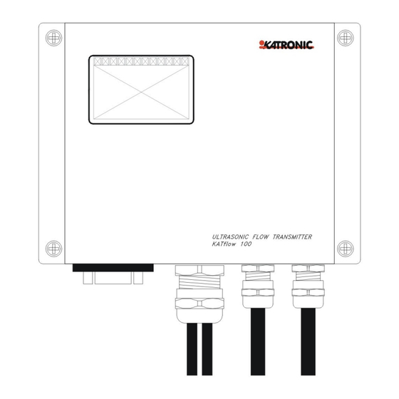
2 Introduction 2 Introduction Clamp-on transit- The KATflow 100 is an ultrasonic flow transmitter employing clamp-on sensors for time flow transmitter the measurement of liquids in full, enclosed pipes. Flow measurements can be undertaken without interruption of the process or interference with the integrity of the pipeline. -
Page 8: Installation
● 3.1.3 Identification of components The following items are typically supplied (please refer to your delivery note for a detailed description): KATflow 100 ultrasonic flow transmitter ● Clamp-on sensors (one pair for single channel operation, two pairs for dual ●... -
Page 9: Clamp-On Sensor Installation
KATflow 100 3 Installation 3.2 Clamp-on sensor installation The correct selection of the sensor location is crucial for achieving reliable measurements and high accuracy. Measurement must take place on a pipe in which sound can propagate (see Acoustic propagation) and in which a rotationally symmetrical flow profile is fully developed (see Straight pipe lengths). - Page 10 KATflow 100 3 Installation For a free inlet or outlet pipe section: Select the measuring point at a location where the pipe cannot run empty. Correct Disadvantageous Correct Disadvantageous For a vertical pipe: Select the measuring point at a location where the liquid flows upward to ensure that the pipe is completely filled.
- Page 11 KATflow 100 3 Installation Disturbance source: 2 x 90°-elbows in different planes Inlet Outlet L ³ 40 D L ³ 5 D Disturbance source: T-section Inlet Outlet L ³ 50 D L ³ 10 D Disturbance source: diffuser Inlet Outlet L ³...
- Page 12 KATflow 100 3 Installation Table 2: Recommended distances from disturbance sources...
-
Page 13: Pipe Preparation
KATflow 100 3 Installation 3.4 Pipe preparation Clean dirt and dust from around the area of the pipework where the ● sensors are to be placed. Remove loose paint and rust with a wire brush or file. ● Firmly bonded paint does not necessarily need to be removed provided the flowmeter diagnostics indicate sufficient signal strength. -
Page 14: Flowmeter Installation
KATflow 100 3 Installation 3.6 Flowmeter installation 3.6.1 Wall mounting The KATflow 100 is a wall mounted device and can be installed using suitable screws and wall plugs according to the following drawings. Flowmeter outline dimensions Drawing 1: Outline dimensions KATflow 100 ultrasonic flowmeter... - Page 15 KATflow 100 3 Installation Drilling aid for wall mounting Drawing 2: Drilling aid for wall mounting Make sure that the ambient temperature is within the -10 ... 60 °C operating temperature range specified for the flowmeter unit.
-
Page 16: Electrical Connections
Please note that in order to supply the unit with MAINS POWER, the equipment Electrical wiring must be protected by suitably sized switches and circuit breakers. 100 ... 240 V AC, 50/60 Hz 10 W 9 ... 36 V DC 10 W Drawing 3: Electrical connection diagram for the KATflow 100 flow transmitter... -
Page 17: Clamp-On Sensor Mounting
KATflow 100 3 Installation 3.7 Clamp-on sensor mounting Before the sensors can be mounted Sensor mounting the installation location should have been determined, ● a sensor mounting method should be chosen, ● the flowmeter must be mechanically and electrically installed, ●... -
Page 18: Correct Positioning Of The Sensors
KATflow 100 3 Installation 3.7.3 Correct positioning of the sensors Correct sensor position Illustration 6: Correct positioning of the sensors Always mount the transducer pair so that the free front edges of the sensors face each other. There is a different engraving on the top of each transducer. The transducers are mounted correctly if the engravings on the two transducers form an arrow. - Page 19 KATflow 100 3 Installation Pull the tension strap and guide the free end through the clamp so that the ● clamp hooks engage. Slightly tighten the screw on the clamp. Mount the second sensor in the same way. ● Press the sensors firmly to the pipe. There should be no air pockets ●...
-
Page 20: Operation
KATflow 100 4 Operation 4 Operation 4.1 Switching On/Off The flowmeter is switched on by connecting the power supply to the instrument. Switching On/Off Disconnecting the external supply switches off the flowmeter. 4.2 Keypad and display (where specified) KF100 Programmer... - Page 21 KATflow 100 4 Operation Character entry: No function Character entry: No function < Character entry: No function > Character entry: No function Character entry: No function Character entry: No function Character entry: No function Move menu/list selection item Character backspace clear...
-
Page 22: Display Functions
KATflow 100 4 Operation ESCape menu item Abort entry without saving Switches the instrument OFF if pressed for more than 2 s ENTER menu item Confirm entry with saving Switches the instrument ON if pressed for more than 2 s 4.2.2 Keypad key functions (internal keypad where specified) -
Page 23: Quick Setup Wizard
KATflow 100 4 Operation Backlight switched on Backlight switched off I/O processor error (internal screen only) I/O processor functioning correctly Without strike-through: Speaker on With strike-through: Speaker off Poor sensor coupling, low SNR (internal screen only) Sensor coupling OK Not used... - Page 24 KATflow 100 4 Operation (Programmer) Use cursor keys to select Setup Wizard. Confirm by pressing <ENTER>. If sensors are recognised, the serial number will be shown. If not recognised or not connected, they may be selected from a list. (Screen – where integral screen specified) Use cursor keys to select Setup Wizard.
- Page 25 KATflow 100 4 Operation Select fluid using cursor keys. Confirm by pressing <ENTER>. Enter process temperature using alphanumerical keys and confirm by pressing <ENTER>. Use key <UP> as character backspace clear to correct for data entry errors. Select pipe lining material using cursor keys.
-
Page 26: Measurements
KATflow 100 4 Operation (Screen) Use cursor keys to select Start Measurement. Confirm by pressing <ENTER>. Sensor positioning screen: Mount transducers with suggested spacing and use middle bar for fine adjustment of position (central position is desired). Observe signal-to-noise (upper bar) and quality (lower bar). -
Page 27: Diagnostic Displays
KATflow 100 4 Operation 3-line display format – (screen only) Display screen Operation three-line display screen configureable to show flow, totalizers and diagnostic functions. Change to diagnostic displays by pressing <DISP> and to totalizer screens by pressing <NEXT>. Cycle through display screens using <NEXT>. -
Page 28: Commissioning
KATflow 100 5 Commissioning 5 Commissioning 5.1 Menu structure – (screen, programmer and software) Alternative specifications are shown in light grey. Menu structure Main menu Menu level 1 Menu level 2 Description/settings Quick Start Setup Wizard Sensor type Indication of sensor type and serial number if automatically detected, otherwise select from list ↑↓... - Page 29 KATflow 100 5 Commissioning Liner c-speed Only if lining material selected 600 ... 6553.0 m/s Liner thickness Only if lining material selected 1.0 ... 99.0 mm Passes Select from list ↑↓ Auto 1...16 Totalizer Off, On, Reset + (positive total), Reset – (negative total)
- Page 30 KATflow 100 5 Commissioning Density 100 ... 2000 kg/m C-speed 800 ... 3500 m/s Temperature -30 ... 300 °C Lining Material Select from material list ↑↓ Thickness 1 ... 99 mm C-speed 600 ... 6553.0 m/s Passes Passes Select from list ↑↓...
- Page 31 KATflow 100 5 Commissioning Units Select from list ↑↓ Min Value Min. process variable (PV) value that corresponds to minimum frequency Max Value Max. process variable (PV) value that corresponds to maximum frequency Damping Additional smoothing of the current output, the higher the damping factor, 1 ...
- Page 32 KATflow 100 5 Commissioning 0 ... 30 m/s Corrected Apply flow velocity profile correction Yes, No PV Offset Calibration process variable zero offset -30 ... 30 units PV Scaling Calibration process variable gradient scaling 0 ... 10000 units Zero Cal...
-
Page 33: Diagnostics
KATflow 100 5 Commissioning Low memory Logger space remaining at low memory alarm Log Wrap Saves "selected" items as a continuous stream without headers (Note : this means files cannot be processed by KATData+) Yes/No Log Download Send logger data using communication port... -
Page 34: Output Configuration
KATflow 100 5 Commissioning 5.4 Output configuration 5.4.1 Serial interface RS 232 Serial interfaces The RS 232 serial interface can be used to transmit data on-line (where specified) or to communicate with the programmer (where applicable). 5.4.2 Serial interface RS 485 / Modbus RTU The RS 485 interface is used for networking up to 32 flowmeters to a centralised computer system. -
Page 35: Analogue Voltage Output
KATflow 100 5 Commissioning 5.4.4 Analogue current output 0/4 ... 20 mA Analogue outputs The analogue current outputs operate in a 4 ... 20 mA or 0 ... 20 mA span. Current outputs may be assigned to process values in the “mode” section of the output menu. -
Page 36: Digital Open-Collector Output
KATflow 100 5 Commissioning 5.4.7 Digital open collector output Digital outputs Open-Collector outputs may be assigned to process values in the “mode” section of the output menu. The outputs are configured using the menu structure. The totaliser function is enabled and controlled using the menu structure... -
Page 37: Analogue Current Input 0/4
KATflow 100 5 Commissioning 5.5.2 Analogue current input 0/4 ... 20 mA Wiring Electrical Active or passive wiring characteristic Measuring range active = 0 ... 20 mA at 30 V Measuring range passive = 4 ... 20 mA Accuracy = 0.1 % of measured value 5.6 Heat quantity measurement (HQM) –... -
Page 38: Scope Function
KATflow 100 5 Commissioning 5.8 Scope function (where provided) Katronic flowmeters have an additional scope function which shows a representation of the pulse received by the sensors. In addition to displaying the received pulse, this screen lists the following data... -
Page 39: Maintenance
KATflow 100 6 Maintenance 6 Maintenance KATflow flowmeters are maintenance free concerning the flow measurement functions. Within the scope of periodic inspections, regular inspection for signs of damage or corrosion is recommended for the transducers, the junction box if installed, and the flowmeter housing. -
Page 40: Troubleshooting
KATflow 100 7 Troubleshooting 7 Troubleshooting Should there be the need to call customer service, please let us know the following details: Model code ● Serial number ● SW, HW revision ● Error log list ● Possible error messages may include the following:... - Page 41 KATflow 100 7 Troubleshooting COMM HS1 ERR Hardware Internal communication Power on/off, otherwise error call customer support COMM READ AVE Hardware Internal communication Power on/off, otherwise error call customer support COMM READ RAW Hardware Internal communication Power on/off, otherwise error...
-
Page 42: Technical Data
KATflow 100 8 Technical data 8 Technical data Sound Speed* Shear Wave (at 25 ºC) Material ft/s Steel, 1% Carbon, hardened 3,150 10,335 Carbon Steel 3,230 10,598 Mild Steel 3,235 10,614 Steel, 1% Carbon 3,220 10,565 302 Stainless Steel 3,120... - Page 43 KATflow 100 8 Technical data All data given at 25 ºC (77 ºF) unless otherwise stated Change Viscosity Sound Speed v/ºC (Kinematic) Chemical Specific Substance ft/s m/s/ºC mm X10-6 ft Formula Gravity Acetic anhydride (CH3CO)2O 1.082 (20 ºC) 1,180 3,871.4 0.769...
- Page 44 KATflow 100 8 Technical data 1,328.7 Methane 0.162 (-89 ºC) 17.5 (-89 ºC) (-128 ºF) Methanol CH4O 0.791 (20 ºC) 1,076 3,530.2 0.695 7.478 Methyl acetate C3H6O2 0.934 1,211 3,973.1 0.407 4.379 Methyl alcohol CH4O 0.791 1,076 3,530.2 0.695 7.478...
- Page 45 KATflow 100 8 Technical data 1,170 3,838.6 Tetrachloroethane C2H2Cl4 1553 (20 ºC) 1.19 12.804 (20 ºC) (68 ºF) Tetrachloro-ethene C2Cl4 1.632 1,036 3,399 Tetrachloro-Methane CCl4 1.595 (20 ºC) 3,038.1 0.607 6.531 Tetrafluoro-methane 875.24 (- 2,871.5 1.75 (-150 ºC) 6.61 (Freon 14) 150 ºC)
- Page 46 KATflow 100 8 Technical data 93.2 1517 4977 95.0 1519 4984 96.8 1521 4984 98.6 1523 4990 100.4 1525 4997 102.2 1527 5010 104.0 1528 5013 105.8 1530 5020 107.6 1532 5026 109.4 1534 5033 111.2 1535 5036 113.0 1536 5040 114.8...
- Page 47 KATflow 100 8 Technical data 188.6 1552 5092 190.4 1551 5089 192.2 1551 5089 194.0 1550 5086 195.8 1549 5082 197.6 1549 5082 199.4 1548 5079 201.2 1547 5076 203.0 1547 5076 204.8 1546 5072 206.6 1545 5069 208.4 1544 5066 210.2...
-
Page 48: Specification
KATflow 100 9 Specification 9 Specification General Measuring principle : Ultrasonic time difference correlation principle Flow velocity range : 0.01 ... 25 m/s Resolution : 0.25 mm/s Repeatibility : 0.15 % of measured value ± 0.015 m/s Accuracy : ± 1 ... 3 % of measured value depending on application, ±... - Page 49 KATflow 100 9 Specification Process inputs / Process Outputs (maximum of four per instrument) Inputs Temperature : PT 100, three or four-wire circuit, measuring range - 50 ... 400 °C, resolution 0.1K, accuracy ±0.2 K Current : 0 ... 20 mA active or 4 ... 20 mA passive, U = 30 V, R = 50 Ohm, accuracy 0.1 % of MV...
-
Page 50: Index
KATflow 100 10 Index 10 Index Acoustic coupling gel Outer Diameter Analogue current input Output Configuration Analogue current output Output settings Analogue frequency output Packaging Analogue voltage output Passes Certificate of Conformity Pipe material selection Commissioning Pipe parameters Customer Return Note (CRN) -
Page 51: Appendix A
KATflow 100 Appendix A Appendix A Certificate of Conformity... -
Page 52: Appendix B
KATflow 100 Appendix B Appendix B Customer Return Note (CRN) Company Address Name Tel. No. E-mail Instrument model Katronic contract no. (if known) Serial number Sensor type(s) Sensor serial number(s) The enclosed instrument has been used in the following environment (please √):...
Need help?
Do you have a question about the KATflow 100 and is the answer not in the manual?
Questions and answers