
Summary of Contents for Motor Power FLEXI PRO
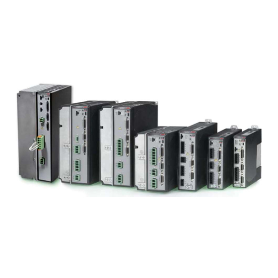
- Page 1 FLEXI PRO Servo Drive Quick Start Guide 120/240 VAC and 400/480 VAC Revision 8.1 Firmware Version 1.41.2 DOC-FLEXI PRO-QSG-EN...
- Page 2 FLEXI PRO Quick Start Guide...
- Page 3 Reggio Emilia - Italia Tel: +39 0522 682710 Fax: +39 0522 683552 Website: www.motorpowerco.com Technical Support If you need assistance with the installation and configuration of the FLEXI PRO drive, contact Motor Power Company Technical Support: info@motorpowerco.it Quick Start Guide...
-
Page 4: Table Of Contents
FLEXI PRO-020/FLEXI PRO-024 (120/240 VAC) ..........17 FLEXI PRO-003/FLEXI PRO-006 (400/480 VAC) ..........19 FLEXI PRO-012 (400/480 VAC) ..............21 Pin Assignments on FLEXI PRO-012 – AP/AF/EC Models ........21 FLEXI PRO-024/FLEXI PRO-030 (400/480 VAC) ..........23 3 Control Board ....................25 Overview ...................... -
Page 5: Introduction
VarCom uses CANopen over EtherCAT (CoE) protocol Manufacturer-Specific: CANopen CANopen – all 2000h objects Standard Servo-Drive (Motion): CANopen – all 6000h objects * Not included in this Quick Start Guide. Refer to the FLEXI PRO User Manual. Quick Start Guide... -
Page 6: Safety
When connecting the FLEXI PRO to other control equipment, be sure to follow two basic guidelines to prevent damage to the drive: The FLEXI PRO must be grounded via the earth ground of the main AC voltage supply. Any motion controller, PLC or PC that is connected to the FLEXI PRO must be grounded to the same earth ground as the FLEXI PRO. -
Page 7: Wiring
FLEXI PRO 2 Wiring FLEXI PRO System Wiring Example of Servo System Wiring, (120/240 VAC) 1-Phase Quick Start Guide... - Page 8 FLEXI PRO Example of Servo System Wiring, (400/480 VAC) 3-Phase Quick Start Guide...
-
Page 9: Flexi Pro Shielding And Bonding
FLEXI PRO FLEXI PRO Shielding and Bonding Quick Start Guide... -
Page 10: Flexi Pro Grounding
FLEXI PRO FLEXI PRO Grounding Quick Start Guide... -
Page 11: Flexi Pro Pin Assignments
FLEXI PRO FLEXI PRO Pin Assignments FLEXI PRO-1D5/FLEXI PRO-003 (120/240 VAC) Pin Assignments on FLEXI PRO-1D5/FLEXI PRO-003 – AP/AF/EC Models Quick Start Guide... - Page 12 FLEXI PRO Pin Assignments on FLEXI PRO-1D5/FLEXI PRO-003 – EB Models Quick Start Guide...
-
Page 13: Flexi Pro-4D5/Flexi Pro-006 (120/240 Vac)
FLEXI PRO FLEXI PRO-4D5/FLEXI PRO-006 (120/240 VAC) Pin Assignments on FLEXI PRO-4D5/FLEXI PRO-006 – AP/AF/EC Models Quick Start Guide... - Page 14 FLEXI PRO Pin Assignments on FLEXI PRO-4D5/FLEXI PRO-006 – EB Models Quick Start Guide...
-
Page 15: Flexi Pro-008/Flexi Pro-010/Flexi Pro-013 (120/240 Vac)
FLEXI PRO FLEXI PRO-008/FLEXI PRO-010/FLEXI PRO-013 (120/240 VAC) Pin Assignments on FLEXI PRO-008/FLEXI PRO-010/FLEXI PRO-013 – AP/AF/EC Models Quick Start Guide... - Page 16 FLEXI PRO Pin Assignments on FLEXI PRO-008/FLEXI PRO-010/FLEXI PRO-013 – EB Models Quick Start Guide...
-
Page 17: Flexi Pro-020/Flexi Pro-024 (120/240 Vac)
FLEXI PRO FLEXI PRO-020/FLEXI PRO-024 (120/240 VAC) Pin Assignments on FLEXI PRO-020/FLEXI PRO-024 – AP/AF/EC Models Quick Start Guide... - Page 18 FLEXI PRO Pin Assignments on FLEXI PRO-020/FLEXI PRO-024 – EB Models Quick Start Guide...
-
Page 19: Flexi Pro-003/Flexi Pro-006 (400/480 Vac)
FLEXI PRO FLEXI PRO-003/FLEXI PRO-006 (400/480 VAC) Pin Assignments on FLEXI PRO-003/FLEXI PRO-006 – AP/AF/EC Models Quick Start Guide... - Page 20 FLEXI PRO Pin Assignments on FLEXI PRO-003/FLEXI PRO-006 – EB Models Quick Start Guide...
-
Page 21: Flexi Pro-012 (400/480 Vac)
FLEXI PRO FLEXI PRO-012 (400/480 VAC) Pin Assignments on FLEXI PRO-012 – AP/AF/EC Models Quick Start Guide... - Page 22 FLEXI PRO Pin Assignments on FLEXI PRO-012 – EB Models Quick Start Guide...
-
Page 23: Flexi Pro-024/Flexi Pro-030 (400/480 Vac)
FLEXI PRO FLEXI PRO-024/FLEXI PRO-030 (400/480 VAC) Pin Assignments on FLEXI PRO-024/FLEXI PRO-030 – AP/AF/EC Models Quick Start Guide... - Page 24 FLEXI PRO Pin Assignments on FLEXI PRO-024/FLEXI PRO-030– EB Models Quick Start Guide...
-
Page 25: Control Board
FLEXI PRO 3 Control Board Overview The control board interfaces vary depending on the specific FLEXI PRO model, as detailed in the following table. Control Board Interfaces Function Interface USB Communication – Controller Interface Machine Interface – Motor Feedback Fieldbus Devices C5 + C6 –... - Page 26 FLEXI PRO Controller Interface (C2) – AP/AF Models Pin Function Description Function Description 24 VDC return Return of the user-supplied 24 VDC User supplied 24V, for I/O biasing 24 VDC Digital output 1 Opto-isolated programmable Digital input 2 Opto-isolated programmable digital output.
- Page 27 FLEXI PRO Controller Interface (C2) – EC Model Pin Function Description Function Description Common output Common input Digital output 1 Opto-isolated programmable Digital input 2 Opto-isolated programmable digital output. Read using OUT1 digital input. Read using IN2 Digital input 1 Opto-isolated programmable digital input.
- Page 28 FLEXI PRO Controller Interface (C2) – EB Model Pin Function Description Function Description Common output Common input Digital output 1 Opto-isolated programmable Digital input 2 Opto-isolated programmable digital output. Read using OUT1 digital input. Read using IN2 Digital input 1 Opto-isolated programmable digital input.
-
Page 29: Controller Interface Wiring
FLEXI PRO Controller Interface Wiring Controller Interface Wiring – AP/AF Models Quick Start Guide... - Page 30 FLEXI PRO Controller Interface Wiring – EC Models Controller Interface Wiring – EB Models Quick Start Guide...
-
Page 31: Machine Interface
FLEXI PRO Machine Interface Note: EB model does not have a Machine Interface. Wire the machine inputs and outputs according to the requirements of your application. AP/AF Models Outputs are opto-isolated, and can be connected as sink only; outputs are compatible with source inputs. -
Page 32: Machine Interface Wiring
FLEXI PRO Pin Function Description Pin Function Description 24 VDC AP/AF Models: User 24 VDC AP/AF Models: Return supplied 24V, for I/O return of the user-supplied biasing 24 VDC Common EC Models Common EC Models input output Fault relay 1 Terminal 1 of the dry... - Page 33 FLEXI PRO Machine Interface Wiring – EC Models Quick Start Guide...
-
Page 34: Motor Feedback
Refer to the guidelines following the pinout table below. Pins 1, 2, 14 and 15 have dual functionality. Pin 25 for the motor temperature sensor is connected internally in the drive to FLEXI PRO ground. Unused pins must remain unwired. Motor Feedback Interface (C4) -
Page 35: Feedback Wiring
FLEXI PRO Feedback Wiring The following tables present suggestions for the most common feedback variations. Refer to the drive’s User Manual for additional information. If your motor feedback does not match any of the following, contact technical support. Use the Flexi SUITE Motor Setup procedure and the Feedback screens to define motor feedback type, resolution, and other parameters. - Page 36 FLEXI PRO Differential Halls Only Wiring – Sine Encoder with Halls Pin # Twisted Pair Signal Description Pin # Twisted Pair Signal Description Hall U+ Twisted Pair Sine Encoder Sine+ Hall U- Sine Encoder Sine- Hall V+ Twisted Pair Sine Encoder Cosine+...
- Page 37 FLEXI PRO Sine Encoder with Index and Halls Sick 8V (HIPERFACE Protocol and Sine Signal) Pin # Twisted Pair Signal Description Pin # Twisted Pair Signal Description Twisted Pair Sine Encoder Sine+ Twisted Pair Serial Data + Sine Encoder Sine-...
-
Page 38: Fieldbus Devices
(Rx) for drives operating on EtherCAT or CANopen networks. Refer to the drive’s EtherCAT and CANopen Reference Manual. Host Computer The FLEXI PRO can be connected to the host computer through either one of two serial interfaces: USB Interface (C1). Use a USB 2.0 A to Mini-B cable. -
Page 39: Daisy Chain
FLEXI PRO Daisy Chain The FLEXI PRO can be addressed and controlled on a daisy-chained RS232 line. In a daisy-chain RS232 configuration, all drives must be daisy-chained through the C8 connector. Each drive must have a unique address to enable its identification on the network. -
Page 40: Power Board 120/240 Vac
Safe torque off (STO) is a safety function that prevents the drive from delivering power to the motor, which can generate torque. STO Enable and STO Return must be connected to enable FLEXI PRO operation. The STO Enable signal voltage must be 24 VDC. -
Page 41: Regeneration Resistor
FLEXI PRO-1D5 and FLEXI PRO-003, 120/240 VAC. AC Input The AC Input interfaces vary among FLEXI PRO 120/240 VAC models. FLEXI PRO-1D5 and FLEXI PRO-003: One interface (P3) for bus power and logic power. FLEXI PRO-4D5 and FLEXI PRO-006: One interface (P4) for bus power and logic power. - Page 42 FLEXI PRO -024 AC Phase 1 AC Phase 2 AC Phase 3 Logic AC Phase 1 Logic AC Neutral AC Input Voltage and Regen are combined on one interface on FLEXI PRO-1D5 and FLEXI PRO-003, 120/240 VAC. Quick Start Guide...
-
Page 43: Power Board 400/480 Vac
Safe torque off (STO) is a safety function that prevents the drive from delivering power to the motor, which can generate torque. STO Enable and STO Return must be connected to enable FLEXI PRO operation. The STO Enable signal voltage must be 24 VDC. -
Page 44: Ac Input And Regeneration Resistor
PRO 400/480 VAC models. Connect the AC input voltage ground wire to the PE terminal, located on the FLEXI PRO front panel. Use an M4 ring or spade terminal. Connect L1, L2 and L3 (for bus power) If the application requires a regeneration (regen) resistor, connect the regen resistor between terminals B1+ and B2. -
Page 45: Software
Drive Configuration In Flexi SUITE, select the Motor Setup wizard from the navigation menu. Follow the prompts to configure the FLEXI PRO for your particular motor. When Motor Setup is complete, use the Flexi SUITE Autotuning wizard to optimize drive parameters for your particular application. -
Page 46: Drive Status (7-Segment Display)
FLEXI PRO 7 Drive Status (7-Segment Display) The 7-segment display provides indications of drive status, such as operation modes, drive enable status, and fault conditions. 7-Segment Display Codes Code Light Type Name Description Action Required Fault Motor Setup Failed Motor Setup procedure failed Check phase and motor wiring. - Page 47 FLEXI PRO Code Light Type Name Description Action Required Fault PLL (phase-locked Controller synchronization signal Check if controller provide loop) is missing or not stable. The fault synchronization signal. Check Synchronization is detected only when the cable connection and Failed synchronization is enabled by wiring.
- Page 48 FLEXI PRO Code Light Type Name Description Action Required e127 Fault Output Over-Current Over-current detected on one of Verify correct wiring of the Detected the digital outputs. digital outputs. Make sure the output circuit is not shorted. This fault disables the drive.
- Page 49 FLEXI PRO Code Light Type Name Description Action Required Fault CAN is in Bus-Off The drive has disconnected from Check CAN cabling, and verify State the CAN bus due to the CAN network is functioning communication errors, and is no properly.
- Page 50 FLEXI PRO Code Light Type Name Description Action Required Warning Software positive Positive software limit switch is limit switch is activated. tripped PFB > POSLIMPOS and POSLIMMODE = 1 Warning Software negative Negative software limit switch is limit switch is activated.
- Page 51 This fault is related to resolver and sine encoder feedback. Fault Feedback 5V Over- The current supplied by the drive The FLEXI PRO can source a Current on the 5V primary encoder maximum current of 250 mA supply has exceeded the preset to the primary encoder.
- Page 52 FLEXI PRO Code Light Type Name Description Action Required Fault Feedback Communication with the Check that the feedback device Communication feedback device did not initialize is wired correctly. Error correctly. Check that the correct encoder type (MENCTYPE) is selected. Fault...
- Page 53 FLEXI PRO Code Light Type Name Description Action Required Fault Encoder Phase Error In normal incremental encoder Set MENCAQBFILT to 0 to operation, quadrature inputs A remove the filter on A and B and B are 90 degrees out of signals.
- Page 54 FLEXI PRO Code Light Type Name Description Action Required Fault A/B Out of Range Feedback analog signal is out of Check the amplitudes of the range. This fault is related to sine and cosine signals. resolver and sine encoder feedback. The drive checks that...
- Page 56 FLEXI PRO Servo Drive Quick Start Guide Motor Power Company s.r.l. Via Leonardo Da Vinci , 4 42024 Castelnovo Sotto Reggio Emilia - Italia Tel: +39 0522 682710 Fax: +39 0522 683552 info@motorpowerco.it www.motorpowerco.com...
Need help?
Do you have a question about the FLEXI PRO and is the answer not in the manual?
Questions and answers