Table of Contents
Advertisement
On-Panel Power Monitor
KM-N3-FLK
model
Users Manual
Thank you for purchasing the On-panel Power Monitor, model KM-N3-
FLK (referred to as model KM-N3 in this manual).
This Users Manual describes the functions, performance, and
application methods needed for optimum use of the unit.
Please observe the following when using this unit.
• This product is designed for use by qualified personnel with a
knowledge of electrical systems.
• Before using the product, thoroughly read and understand this Users
Manual to ensure correct use.
• Keep this Users Manual in a safe location so that it is available for
reference whenever required.
Catalog no. N214-E1-02
1. Overview of the unit
2. Installation and wiring
3. Basic use
4. Settings needed to measure
electricity
5. Other Functions
6. Detailed settings for communications
7. Troubleshooting
8. Appendices
Advertisement
Table of Contents
Troubleshooting

Summary of Contents for Omron KM-N3-FLK
- Page 1 On-Panel Power Monitor KM-N3-FLK model Users Manual 1. Overview of the unit 2. Installation and wiring 3. Basic use 4. Settings needed to measure electricity 5. Other Functions 6. Detailed settings for communications 7. Troubleshooting Thank you for purchasing the On-panel Power Monitor, model KM-N3- FLK (referred to as model KM-N3 in this manual).
-
Page 2: Table Of Contents
Index Agreement regarding use ....................4 Safety precautions ......................6 Important safety points......................8 Precautions for correct use....................9 Manual revision history ....................11 1. Overview of the unit 1.1 Main features ......................12 1.2 Device configuration ....................13 1.3 Names of the parts and their functions..............14 1.4 Dimensions .........................16 1.5 Multi-circuit metering ....................17 1.6 Multi-address system....................19... - Page 3 Index (continued) 4. Settings needed to measure electricity 4.1 Setting items for measuring electricity ..............48 4.2 Circuit settings ......................49 4.3 RS-485 communication settings ................55 4.4 Pulse output settings ....................58 5. Other Functions 5.1 Voltage assignment....................59 5.2 Measuring high voltage .....................60 5.3 Display unit conversion .....................61 5.4 Automatic LCD OFF ....................62 5.5 Alarm display with negative effective power value..........63...
-
Page 4: Agreement Regarding Use
Confirm beforehand that Omron Products are properly wired and installed for their intended use in your overall system. When using Omron Products, make sure to (i) maintain a margin of safety in relation to the published rated and performance values, such as introducing redundancy, (ii) design to minimize risks to any Customer Application in case of failure of any Omron Products, (iii) adopt system-wide safety measures to notify risks to users, and (iv) conduct regular maintenance on Omron Products and Customer Application. - Page 5 Replacement of the malfunctioning Omron Product(s) with the same number of replacement/alternative products at no charge to the customer. Exceptions: This warranty of Omron Products does not apply if the cause of the malfunction falls under any of the following: Usage in a manner other than the original intended use for the Omron Products.
-
Page 6: Safety Precautions
Safety precautions Regarding the displays used to ensure safe operation and their meanings The following indications and symbols are used in this manual for precautions so that you can use the product safely. The precautions here include important information regarding safety. Please follow these instructions. The indications and symbols are as follows. - Page 7 Safety precautions(continued) Caution Property damage may occur due to fire. Tighten the terminal screws to the specified torques. After tightening the screw, check that the screw is not loose. M3 screw : 0.5 to 0.58N·m Minor or moderate injury or property damage may occur due to explosion. Do not use in locations exposed to flammable or explosive gases.
-
Page 8: Important Safety Points
Important safety points Observe the following to ensure safe use of model KM-N3. • Do not use or store the product in any of the following locations. – Locations subject to shock or vibration – Unstable locations where the user might fall/tumble down –... -
Page 9: Precautions For Correct Use
• You cannot use the CT dedicated for use with the Omron KM series (model series KM20-CTF, model series KM- NCT) . Use a CT whose secondary output is 1A or 5A. - Page 10 Precautions for correct use (continued) Safety standard compatibility If the equipment is used by a method not specified by the manufacturer, the equipment might lose the equipped protection. The temporary overvoltage occurring on the main power supply must not exceed the following values: Confirm the voltage using the power supply voltage of the product that you purchased.
-
Page 11: Manual Revision History
Manual revision history A manual revision code appears as a suffix to the catalog number on the front cover and back cover of the manual. Catalog no. N214-E1-02 Revision number Revision Date of revision Reason for revision, pages revised number 01 A August 2016 First edition... -
Page 12: Overview Of The Unit
CompoWay/F is Omron's unified communication procedure for general serial communications. It has a unified framework format and has commands compliant with FINS which works well with Omron programmable controllers, for instance, simplifying communications between host devices (computers for example) and components. -
Page 13: Device Configuration
For example: Model KM-N3-FLK Generic CT RS-485 Host device Modbus CompoWay/F Generic CT Breaker Operating power You cannot use the CT dedicated for use with the Omron KM series (model series KM20-CTF, model series KM- NCT, etc.) with this unit. -
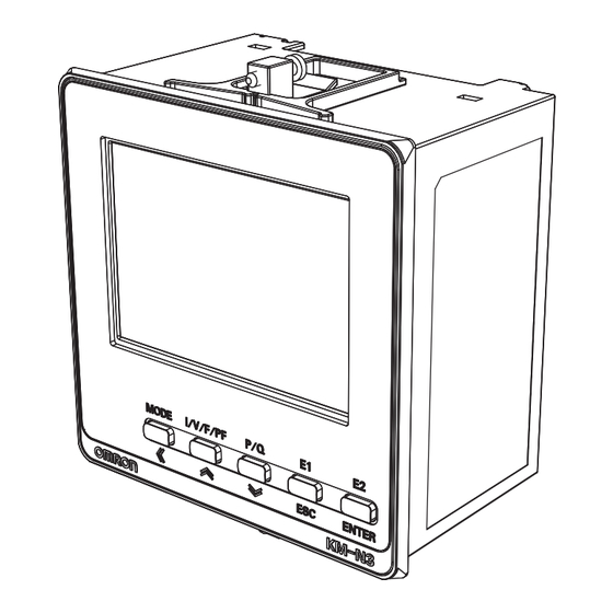
Page 14: Names Of The Parts And Their Functions
1. Overview of the unit 1.3 Names of the parts and their functions <Front> <LCD display details> Item Description Long press: The measurement mode is switched with the setup mode. [MODE] key (measurement mode): The measurement circuit is changed. MODE• Key ] key (setup mode): Change of the measurement circuit / Digit shifting when a numerical value is input [I/V/F/PF] key (measurement mode): The display of current, voltage,... - Page 15 1. Overview of the unit 1.3 Names of the parts and their functions (continued) <Right side surface> <Rear> <Left side surface> Item Description RESETTABLE Lit when resettable integrated electric energy is displayed. Measurement auxiliary ----- Lit when integrated leading reactive electric energy is displayed. display Total Q Lit when total integrated reactive electric energy is displayed.
-
Page 16: Dimensions
1. Overview of the unit 1.4 Dimensions Units (mm) (64) Panel cut-out dimensions for mounting +0.8 Optional Products (Order Separately) Terminal Covers Waterproof Packing E53-COV24 (Three Covers provided.) Y92S-P10 (for DIN 96 × 96) The Waterproof Packing is provided with the KM-N3. Order the Waterproof Packing separately if it becomes lost or damaged. -
Page 17: Multi-Circuit Metering
1. Overview of the unit 1.5 Multi-circuit metering Multi-circuit metering is possible with this product. Measuring circuit refers to the measurement point where electricity measuring is conducted. Furthermore, this product measures voltage commonly across all circuits and measures current with each separate circuit by using generic CTs. ●... - Page 18 1. Overview of the unit 1.5 Multi-circuit metering (continued) ● Allocating the circuits used and the CTs for each phase and wire type The following table shows the phase and wire types and the CT allocations for each measuring circuits. As circuit A is used irrespective of the phase and wire type, you must make settings for measurement ("Circuit A settings(...
-
Page 19: Multi-Address System
1. Overview of the unit 1.6 Multi-address system This product is a multi-address system where different communications addresses (numbered in order) are allocated to each circuit.The communications addresses correspond to each measuring point, so data transmission management from the host device is simplified. The following diagram is an overview of the multi-address system. -
Page 20: Mode Configuration
1. Overview of the unit 1.7 Mode configuration This model has three modes: measuring mode, setting mode, and communication setting mode. – Measuring mode: The measured values for each circuit are displayed. – Setting mode: By operating keys on the body of the unit you can change settings for each of the circuits, and make common settings for communications, output, the display, etc. -
Page 21: Installation And Wiring
2. Installation and wiring 2.1 Attaching the body of the unit For safety purposes, install the unit in a location where you won't touch the terminals when operating the main unit. For example, install so that the terminals are hidden within the control board so that a person working on the unit will not be able to touch live wires. - Page 22 2. Installation and wiring 2.1 Attaching the body of the unit (continued) Fit the attached mounting adapter into the fixing grooves on the top and bottom faces of the rear case. Push in the mounting adapter from the terminal side until it contacts the panel to fix the main unit tentatively.
-
Page 23: Wiringthe Cts
2. Installation and wiring 2.2 Wiring the CTs You can connect up to a maximum of 4 generic CTs to this unit ( 17). The number of CTs used depends on the phase and wire type of the power source being monitored. The following table shows the phase and wire types and the CTs to use for each. For example, use CT1 when measuring only one 1-phase 2-wire circuit. - Page 24 2. Installation and wiring 2.2 Wiring the CTs (continued) Important • For safety purposes, turn off the mains power and the breaker to ensure there is no power supply while you are working. • Do not try to connect or disconnect CTs or CT cables during measurement or while the power of this product is on.
-
Page 25: Wiring The Power Supply
2. Installation and wiring 2.3 Wiring the power supply Wire the input of the operational power supply with the power supply terminal. The terminal layout of the power supply is as follows. Power supply voltage 100 to 240 VAC Terminal (Insertion) hole Release hole Wiring 8 mm... -
Page 26: Wiring The Measured Voltage Input
2. Installation and wiring 2.4 Wiring the measured voltage input To measure voltage, wire the measured voltage input terminal. The terminal layout of the measured voltage input terminals is as follows. Voltage input terminals Voltage input terminals Phase and wire type 4-phase 3-wire 1-phase 2-wire ̶... - Page 27 2. Installation and wiring 2.4 Wiring the measured voltage input (continued) Wire the device according to the phase and wire type as shown in the following diagram. Install a circuit breaker between the measured voltage input terminal and each wiring of R/S/T/N, L/N, and R/N/T so that the power supply can be turned OFF quickly.
-
Page 28: Fitting The Cts To The Measuring Wires
2. Installation and wiring 2.5 Fitting the CTs to the measuring wires When monitoring one circuit with 1-phase 2-wire, you need one CT. When monitoring one circuit with 1-phase 3-wire, you need 2 CTs. When monitoring one circuit with 3-phase 4-wire, you need 3 CTs. The following diagram is an example of fitting CTs when monitoring one circuit with 1-phase 2-wire. -
Page 29: Pulse Output Wiring
2. Installation and wiring 2.6 Pulse output wiring Wire the pulse output terminals if using the pulse output feature. The layout of pulse output terminals is as follows. Pulse output terminal Terminal Terminal Description number name OUT1 Pulse output 1 OUT2 Pulse output 2 OUT3... - Page 30 2. Installation and wiring 2.6 Pulse output wiring (continued) The following diagram shows wiring for pulse output. This unit is equipped with 4 pulse outputs. The common terminal is used commonly. NPN output connection diagram PNP output connection diagram + −...
- Page 31 2. Installation and wiring 2.6 Pulse output wiring (continued) Cautions when connecting the Push-In Plus terminal Follow the below steps when connecting the Push-In Plus terminal (Power supply terminal, RS-485 communication terminal, and pulse output terminal). 1 Connecting Wires to Push-In Plus Terminal Block •...
- Page 32 Phoenix Contact SZF 0-0.4 x 2.5 * 0.4 x 2.5 x 75 302 Wiha AEF.2.5 x 75 Facom 210-719 Wago SDI 0.4 x 2.5 x 75 Weidmuller * SZF 0-0.4 x 2.5 (Phoenix Contact) is can be arranged from Omron XW4Z-00B.
-
Page 33: Wiring
2. Installation and wiring 2.7 RS-485 wiring Wire the RS-485 terminals if using the RS-485 communication feature. The layout of RS-485 terminals is as follows. RS-485 terminal Terminal Terminal Description number name RS-485 + + terminal for RS-485 RS-485 - - terminal for RS-485 RS-485 + + terminal for RS-485 (for crossover wiring) - Page 34 • If the upstream device does not support RS-485 communications, refer to the table below to select a converter for your purpose. Protocol KM-N Setting Tool USB/RS-485 converter operability confirmed Modbus SI-35USB (LINEEYE Co., Ltd.) CompoWay/F K3SC-10 (Omron), SI-35USB (LINEEYE Co.,Ltd.)
-
Page 35: Wiring Diagrams
2. Installation and wiring 2.8 Wiring diagrams The below table shows the wiring for voltage, current, and CT by each phase and wire type. ■ For 3-phase 4-wire 3-phase 4-wire measures one circuit, as shown in the following diagram. Power side R S T N Circuit A (CT1 to 3) Load... - Page 36 2. Installation and wiring 2.8 Wiring diagrams (continued) ■ For 1-phase 3-wire As shown below, 1-phase 3-wire can measure a maximum of 2 circuits. Use CT1,CT2 when measuring only 1 circuit. The CT must be attached to the R-phase and the T-phase. Power side Circuit A (CT1 to 2) Load...
- Page 37 2. Installation and wiring 2.8 Wiring diagrams (continued) The following wiring is also possible as a further method of measuring. ■ For 1-phase 2-wire voltage selected The 1-phase 2-wire branching off from the 1-phase 3-wire is measured. With this connection, a setting is required according to which of R-N phase, T-N phase, or R-T phase is connected to the 1-phase 2-wire circuit.
-
Page 38: Basic Use
3. Basic use 3.1 Turning the power on Important • Before turning on the power, ensure that there are no problems with the wiring. Turn ON the circuit breaker to power up this product. • The software version is displayed on the main display, and model "KM-N3" is displayed on the first display. •... -
Page 39: Switching Between Modes
3. Basic use 3.2 Switching between modes Switching between the measuring mode and the setting mode Switch between the measuring mode and setting mode by pressing and holding the [<</MODE] key. • "Press and hold" means pressing the key for 1 or more seconds. ■... - Page 40 3. Basic use 3.2 Switching between modes (continued) Switching between the setting mode and the communication setting mode You can switch between the setting mode and the communication setting mode by sending particular commands. Refer to "6.Detailed settings for communications ( 69)" for details about the commands. It is not possible to move from the communication setting mode to the setting mode.
-
Page 41: How To Read The Measurements
3. Basic use 3.3 How to read the measurements The measurements are shown for circuits A to D in the measuring mode. Depending on the phase and wire type selected, the display changes as follows. The parts in broken lines (circuits B to D) are displayed if you have enabled the circuit settings ( 52). 3-phase 4-wire Circuit A (3P4W) - Page 42 3. Basic use 3.3 How to read the measurements (continued) ● Switching circuits When the [MODE• ] key is pressed, the measuring items are displayed after the screen for showing the destination circuit. • The measuring items for circuits B to D are displayed when the circuit settings are enabled (ON). •...
- Page 43 3. Basic use 3.3 How to read the measurements (continued) ■ Measurement display list Instantaneous value Item Integrated value display units display Current 0.000 to 9999 ----- Voltage A *1 0.000 to 9999 ----- V/kV I/V/F/PF Voltage B *2 0.000 to 9999 ----- V/kV Frequency...
-
Page 44: How To Read The Setting Values
3. Basic use 3.4 How to read the setting values The setting mode is organized into the categories "Individual setting items for circuits A to D", "Common settings", and "Other settings". Category Description Circuits (A, B, C, D) Individual setting items for the circuits Common (CMMN) Setting items common to all of the circuits (communication, pulse output, etc.) Others (ETC) - Page 45 3. Basic use 3.4 How to read the setting values (continued) ● How to switch setting items When the [MODE• ] key is pressed, the setting items are displayed after the screen for showing the destination circuit. • The setting items for circuits B to D are displayed when the circuit settings are enabled (ON). •...
- Page 46 3. Basic use 3.4 How to read the setting values (continued) ■ Setting item list Main display Default MENU No. Setting Item Remarks Display of options and input values Value 3P4W: 3-phase 4-wire, 1P2W: 1-phase 2-wire 3P4W / 1P2W /1P3W / 3P3W /1P2W2 / 1P3W: 1-phase 3-wire, 3P3W: 3-phase 3-wire Phase and wire type 3P4W...
- Page 47 3. Basic use 3.4 How to read the setting values (continued) Main display Default MENU No. Setting Item Remarks Display of options and input values Value Protocol MODBS / COMPF MODBS 1.2K / 2.4K /4.8K Communication speed 9.6K 9.6K / 19.2K / 38.4K(bps) Modbus: 8 (fixed) Data length 7 / 8...
-
Page 48: Settings Needed To Measure Electricity
4. Settings needed to measure electricity 4.1 Setting items for measuring electricity The following are the setting items for measuring electricity. Setting category: Circuits (A, B, C, D) Circuit A setting items ( 49) Circuit B to D setting items ( ... -
Page 49: Circuit Settings
4. Settings needed to measure electricity 4.2 Circuit settings Correct measurement requires the correct settings for phase and wire type, CT secondary side, and CT primary side. If points of measurement are added, enable the use of circuits B to D and set them. ●... - Page 50 4. Settings needed to measure electricity 4.2 Circuit settings (continued) Setting up the communication address (Ex.: set to 15) 1 On the setup items of circuit A, press [ ] or [ ] key to move to the "Communication address (MENU A2)." 2 Press the [ENTER] key to enter the setup mode.
- Page 51 4. Settings needed to measure electricity 4.2 Circuit settings (continued) Set pulse output ON or OFF(MENU A6) (Ex.: set to ON) 1 From the circuit A setting item, press the [ ] keys to move to "Pulse output ON/OFF (MENU A6)". 2 Press the [ENTER] key to enter the setting mode.
- Page 52 4. Settings needed to measure electricity 4.2 Circuit settings (continued) ● Settings for circuits B to D (when measuring 2 circuits or more) This product can measure up to 4 circuits. If you increase the number of circuits, you must enable the circuits and set the items for them.
- Page 53 4. Settings needed to measure electricity 4.2 Circuit settings (continued) Set the CT primary current for the circuits enabled from B to D (Ex.: set the CT primary current for circuit C to 50A) 1 From the circuit C setting item, press the [ ] keys to move to "CT primary current (MENU C4)".
- Page 54 4. Settings needed to measure electricity 4.3 RS-485 communication settings For communications settings other than the communications address, set in the common settings in the settings mode. All circuits will have the same setting. • You can cancel a change by pressing the [ESC] key before confirming the change. ■...
-
Page 55: Rs-485 Communication Settings
4. Settings needed to measure electricity 4.3 RS-485 communication settings (continued) ■ Set the data bit length (Ex.: set to 7 bits) Can only be set when the protocol is CompoWay/F. 1 Press the [MODE• ] key to move to the common settings "CMMN" category display screen. 2 From the common setting items, press the [ ] keys to move to "Data length (MENU 02)". - Page 56 4. Settings needed to measure electricity 4.3 RS-485 communication settings (continued) ■ Set the vertical parity (Ex.: set to ODD) Select "NONE" for no parity, "EVEN" for even parity, and "ODD" for odd parity. 1 Press the [MODE• ] key to move to the common settings "CMMN" category display screen. 2 From the common setting items, press the [ ] keys to move to "Parity (MENU 04)".
-
Page 57: Pulse Output Settings
4. Settings needed to measure electricity 4.4 Pulse output settings This product has 4pulse output ports (OUT1, OUT2, OUT3, OUT4). You can set output ON or OFF for each output port in the pulse output settings. When the active energy exceeds the output units, a pulse wave is output from the ports for which pulse output is set to ON. -
Page 58: Other Functions
5. Other Functions 5.1 Voltage assignment If the phase and wire type has been set to 1-phase 2-wire voltage selected (1P2W2) or 1-phase 3-wire composite (1P3W2), then you need to set the voltage for the 1-phase 2-wire circuit doing the measuring. Set either R-N phase or T-N phase if the input voltage is AC100V, and set R-T phase of the input voltage is AC200V. -
Page 59: Measuring High Voltage
5. Other Functions 5.2 Measuring high voltage If the line voltage measured is 480V or more, for example, measuring 6,600V in the cubicle, use a transformer to convert the line voltage within the input voltage range of this product. Set the multiplication factor from the primary voltage value and the secondary voltage value. -
Page 60: Display Unit Conversion
5. Other Functions 5.3 Display unit conversion You can display a value calculated by multiplying the integrated electric energy of each circuit by a specified coefficient. You can convert the active energy to a monetary figure or volume of CO ■... -
Page 61: Automatic Lcd Off
5. Other Functions 5.4 Automatic LCD OFF This feature turns the LCD display off after the set time elapses. When the LCD is off, it can be turned on again by operating any key. When Automatic LCD OFF is turned OFF, the LCD display is always lighting. ■... -
Page 62: Alarm Display With Negative Effective Power Value
5. Other Functions 5.5 Alarm display with negative effective power value This is a function to display an alarm if effective power becomes a negative value. ( 97). • If the phase of the voltage and current differ and the active power is a negative value, the error is "Active power is a negative value". -
Page 63: Tariff Feature
5. Other Functions 5.6 Tariff feature This feature allows you to select a location to save cumulative active energy data from T1 to T4. Using the tariff feature allows you to, for example, change the location to save active energy so that you can later on check the sum of active energy during a particular time period (for example, night and day when the electricity charges are different). -
Page 64: Change Password
5. Other Functions 5.7 Change password • This enables you to change the password that you need to enter when moving from the measuring mode to the setting mode. • You can set a password of 4 numerals between 0000 and 9999. •... -
Page 65: Checking Software Version
5. Other Functions 5.8 Checking software version You can check the version of software this product is using. ■ Checking software version If a measured value is displayed, press and hold the [MODE• ] key and enter your password to switch to the setting mode. -
Page 66: Initialize
5. Other Functions 5.9 Initialize There are three different types of initialization. (1) Resetting the active energy for each circuit (2) Resetting the active energy for all circuits (3) Resetting the active energy and setting values for all circuits • Setting values remain unchanged if you do either (1) or (2). •... - Page 67 5. Other Functions 5.9 Initialize (continued) ■ Resetting the active energy for all circuits If a measured value is displayed, press and hold the [MODE• ] key and enter your password to switch to the setting mode. 1 Press the [MODE• ] key to move to the other settings "ETC" category display screen. 2 From the other setting items, press the [ ] keys to move to "All active energy reset (MENU 91)".
-
Page 68: Restart
5. Other Functions 5.10 Restart Restart this product. ■ Restarting If a measured value is displayed, press and hold the [MODE• ] key to enter a password to move to the setup mode. 1 Press the [MODE• ] key to move to the other settings "ETC" category display screen. 2 From the other setting items, press the [ ] keys to move to "Restart (MENU 93)". -
Page 69: Detailed Settings For Communications
6. Detailed settings for communications 6.1 Overview of communications Using the communications features enables you to create programs on host devices (such as computers) to collect the data measured by this product and to change its settings. Each circuit on this product is allocated different communications addresses (numbered in order). (... -
Page 70: Modbus
6. Detailed settings for communications 6.2 Modbus ● Data format In the following explanations, values preceded by H' (as in H'02) indicate hexadecimal values. The numbers under the frame sections are the number of bytes. Also, the transfer code is binary for Modbus. ■... - Page 71 6. Detailed settings for communications 6.2 Modbus (continued) ■ Response frame when there is an error Commun Function Error ication CRC-16 code code address Communication address The number specified by the command from is inserted as is. This is the communication address that returned the response. Function code In the response frame when an error occurs, the addition of "H'80"...
- Page 72 6. Detailed settings for communications 6.2 Modbus (continued) ● List of function codes (FC) Function code Name Description 03(H’03) Variable area reading Variable area is read successively. 16(H’10) Variable area writing Variable area is written successively. 06(H’06) Command Operations are performed according to commands. 08(H’08) Echo back test Echo back test is performed.
- Page 73 6. Detailed settings for communications 6.2 Modbus (continued) ● Service details ■ Variable area read (03: H’03) This service allows you to read all variable areas. Reading of the variable areas is conducted by setting the required data in the following command frame.To read setting values "Parameter area list (...
- Page 74 6. Detailed settings for communications 6.2 Modbus (continued) Response frame Commu Function Byte nication Data 1 Data 1 Data 2 Data 2 code Counter address H’03 Upper Lower Upper Lower 4 bytes worth of the number of elements Data n Data n CRC-16 Upper...
- Page 75 6. Detailed settings for communications 6.2 Modbus (continued) ■ Variable area writing (16: H’10) Writing to the variable areas is conducted by setting the required data in the following command frame. The parameter area can be written to. Before writing, you need to first move to the setting mode with a command. The content written is reflected by moving to the measuring mode in response to an instruction after writing of the parameters.
- Page 76 6. Detailed settings for communications 6.2 Modbus (continued) Response frame Commu Function Start writing Number of nication CRC-16 code address elements address H’10 • Start writing address The start writing address that was received. • Number of elements The number of elements that were received. •...
- Page 77 6. Detailed settings for communications 6.2 Modbus (continued) ■ Command (06: H’06) Command frame Commu Function Start writing Written data CRC-16 nication code address address H’06 H’FF H’FF Fixed Fixed Response frame Commu Function Start writing Written data CRC-16 nication code address address...
- Page 78 6. Detailed settings for communications 6.2 Modbus (continued) Command/Response example The following is an example of an instruction for clearing the active energy. (Communication address: When H’01) Command code: "03" Related information: "00" Command Commu Function Start writing nication Written data CRC-16 code address...
-
Page 79: Compoway/F
6. Detailed settings for communications 6.3 CompoWay/F ● Data format In the following explanations, values preceded by H' (as in H'02) indicate hexadecimal values. Only items expressed as normal numerals or characters indicate ASCII characters. The numbers under the frame sections are the number of bytes. ■... - Page 80 6. Detailed settings for communications 6.3 CompoWay/F (continued) ■ Response frame Communication Sub-address Exit code Command text address Fixed Fixed Exit Name Description Error detection code Priority Normal end This indicates that the command ended normally and None that there was no error. FINS command error The specified FINS command could not be executed.
- Page 81 6. Detailed settings for communications 6.3 CompoWay/F (continued) For example: The sub-address is less than 2 characters and there is no SID or FINS-mini Command Communication address The sub-address lacks a character Response Communication Sub-address Exit code address The sub-address is "00" and the exit code is "16" (a sub-address error). ●...
- Page 82 6. Detailed settings for communications 6.3 CompoWay/F (continued) ● Type code The type codes used with this product are as follows. ■ Variable area Variable type code Description The measured values ■ Parameter area Variable type code Description C000 The parameter values for various settings ●...
- Page 83 6. Detailed settings for communications 6.3 CompoWay/F (continued) ● List of response codes When normal end code Name Description Priority 0000 Normal end No error. None When an error occurs code Name Description Priority 0401 Unsupported command This is an unsupported service function. 1001 Over command length The command length is too long.
- Page 84 6. Detailed settings for communications 6.3 CompoWay/F (continued) ● Service details Addresses, numbers of elements, and data re shown in hexadecimal notation. ■ Variable area read (0101) Variable area is read. Service request PDU Variable Start reading Number of Type address Position elements...
- Page 85 6. Detailed settings for communications 6.3 CompoWay/F (continued) Example of read variable area communications This example shows how to read the two measurement values with one command when the measurement is of voltage 1 at 103.7V and voltage 2 at 103.6V Command “(H’02) 0000...
- Page 86 6. Detailed settings for communications 6.3 CompoWay/F (continued) ■ Read parameter area (0201) Parameter area is read. Service request PDU Parameter type Start reading Number of address elements Service response PDU (normal) Response Parameter Start Number of Read data code Type reading elements...
- Page 87 6. Detailed settings for communications 6.3 CompoWay/F (continued) Example of read parameter area communications This example shows how to read two settings with one command where the phase and wire type is set to 1-phase 2-wire and the communications address is 10 Command "(H’02) C000...
- Page 88 6. Detailed settings for communications 6.3 CompoWay/F (continued) ■ Write parameter area (0202) Writing to the parameter area starts. This service is made valid by using a command to move to the settings mode. The content written is reflected by moving to the measuring mode in response to an instruction after writing of the parameters.
- Page 89 • Model The model is displayed in 10 bytes of ASCII code. Space codes are used if the model doesn't take up 10 bytes. For example: This will be as follows for model KM-N3-FLK • Buffer size The buffer size 230 is read as "00E6" (fixed value).
- Page 90 6. Detailed settings for communications 6.3 CompoWay/F (continued) ■ Controller status read (0601) Reads operational state and error status. Service request PDU Service response PDU (normal) Response code Operational Related state information • Operational state Operational state Description The unit is measuring without error. An error has occurred and measuring has stopped.
- Page 91 6. Detailed settings for communications 6.3 CompoWay/F (continued) ■ Echo back test (0801) Echo back test is performed. Service request PDU Test data 0 to 200 Service response PDU (normal) Response code Test data 0 to 200 • Test data Set any test data within the range 0 to 200.
- Page 92 6. Detailed settings for communications 6.3 CompoWay/F (continued) ■ Command (3005) Used when remotely controlling the unit. Service request PDU Instruction Related code information Service response PDU (normal) Response code • List of command codes and related information Related information is fixed at 00. Instruction code Related Instruction details...
-
Page 93: Address Map
6. Detailed settings for communications 6.4 Address map ● List of variable areas (measurement values) Used when remotely controlling the unit. address Type Item CompoWay/F Modbus RTU 0000 0000 Voltage V1 (voltage x 10) 0001 0002 Voltage V2 (voltage x 10) 0002 0004 Voltage V3 (voltage x 10) - Page 94 6. Detailed settings for communications 6.4 Address map (continued) address Type Item CompoWay/F Modbus RTU 0120 0240 Integrate effective energy (Wh) 0121 0242 Integrate regenerative energy (Wh) 0122 0244 Integrated reactive energy of advance (Wh) 0123 0246 Integrated reactive energy of delay (Wh) Measured value 0124 0248...
- Page 95 6. Detailed settings for communications 6.4 Address map (continued) ● Parameter area list Address Type Item CompoWay/F Modbus RTU Phase and wire type H'00000000 : 1P2W H'00000001 : 1P3W 1000 2000 H'00000002 : 3P3W H'00000003 : 1P2W2 H'00000004 : 1P3W2 H'00000005 : 3P4W Communication address 1001...
- Page 96 6. Detailed settings for communications 6.4 Address map (continued) address Type Item CompoWay/F Modbus RTU VT-ratio setup 1107 220E VT ratio x 100 100 to 99999 Conversion factor 1108 2210 Factor x 100 0 to 99999 LCD OFF waiting time 0 : OFF 110A 2214...
-
Page 97: Troubleshooting
7. Troubleshooting 7.1 Warnings Warnings come as errors and alarms. The types of errors and alarms are described below. Warning type Description Display Action to take Setting value error Internal memory corrupted Measured value Internal memory corrupted Contact the place of purchase or Error error the manufacturer. -
Page 98: Troubleshooting
7. Troubleshooting 7.2 Troubleshooting Check if an issue is covered by the following items if the product doesn't seem to be working correctly. Phenomena Description Action to take Page The main unit doesn't start Is the LCD display off? The unit isn't being supplied with power. Check that the voltage terminals have ... - Page 99 7. Troubleshooting 7.2 Troubleshooting (continued) Phenomena Description Action to take Page There is a large Does the selected phase Wire correctly. 35 discrepancy in measured and wire type match the values wiring? 13 Does the CT match the Check the secondary current and secondary current and primary current of the CT you are using...
- Page 100 7. Troubleshooting 7.2 Troubleshooting (continued) Phenomena Description Action to take Page RS-485 communications Is the wiring correct? Wire correctly. 33 not possible Are the communications Check that the communications settings 54 settings correct? between this product and the host system match.
- Page 101 8. Appendices 8.1 Specifications ■ Main unit specifications Item Content Rated input voltage AC100 to 240V Rated frequency 50/60Hz Variation range of power 85 to 110% of rated power supply voltage supply voltage Variation range of power 45 to 65Hz supply frequency Power consumption 7VA or less...
- Page 102 Maximum current for CT secondary side * You cannot use the CT dedicated for use with the Omron KM series (model series KM20-CTF, model series KM- NCT). Use a CT with a rated load of 1.0 VA or more. ■ Output specifications...
-
Page 103: Appendices
8. Appendices 8.2 ASCII code table Binary Decimal Hexadecimal Character Binary Decimal Hexadecimal Character 0000000 0100000 0000001 0100001 0000010 0100010 " 0000011 0100011 0000100 0100100 0000101 0100101 0000110 0100110 & 0000111 0100111 ’ 0001000 0101000 0001001 0101001 0001010 0101010 0001011 0101011 0001100 0101100... - Page 104 8. Appendices 8.2 ASCII code table (continued) Binary Decimal Hexadecimal Character Binary Decimal Hexadecimal Character 1000000 1100000 1000001 1100001 1000010 1100010 1000011 1100011 1000100 1100100 1000101 1100101 1000110 1100110 1000111 1100111 1001000 1101000 1001001 1101001 1001010 1101010 1001011 1101011 1001100 1101100 1001101 1101101...
-
Page 105: Segment Displays And 7 Segment Displays
8. Appendices 8.3 14 segment displays and 7 segment displays The following are some examples of 14 segment displays and 7 segment displays as shown on the LCD of this product. (example of 14 segment display) (example of 7 segment display) - Page 106 The Netherlands Hoffman Estates, IL 60169 U.S.A. Tel: (31)2356-81-300/Fax: (31)2356-81-388 Tel: (1) 847-843-7900/Fax: (1) 847-843-7787 © OMRON Corporation 2016-2017 All Rights Reserved. OMRON (CHINA) CO., LTD. OMRON ASIA PACIFIC PTE. LTD. In the interest of product improvement, Room 2211, Bank of China Tower, No.
Need help?
Do you have a question about the KM-N3-FLK and is the answer not in the manual?
Questions and answers