Table of Contents
Advertisement
Quick Links
ANTTI-TEOLLISUUS OY
Koskentie 89
FI-25340 Kanunki, Salo
Tel. +358 2 774 4700
Fax +358 2 774 4777
E-mail: antti@antti-teollisuus.fi
www.antti-teollisuus.fi
Installation and Operating
Instructions
VULCAN M10 DRYER
HEATERS
(HIPRESS & VACBOOST)
200, 300, 400, 500, 700, 1000,
1400, 2000
408100 (en)
11-2016
Advertisement
Table of Contents

Summary of Contents for ANTTI-TEOLLISUUS OY 200
- Page 1 Installation and Operating Instructions VULCAN M10 DRYER HEATERS (HIPRESS & VACBOOST) 200, 300, 400, 500, 700, 1000, 1400, 2000 408100 (en) ANTTI-TEOLLISUUS OY Koskentie 89 FI-25340 Kanunki, Salo Tel. +358 2 774 4700 Fax +358 2 774 4777 E-mail: antti@antti-teollisuus.fi 11-2016 www.antti-teollisuus.fi...
-
Page 2: Table Of Contents
Assembly drawing, outlet cone 1400/2000 A75038 .................... 32 Installing the shield on the 1400/2000 burners ..................... 34 Vulcan 200 and 300 kW dimension drawing, Positive pressure ................36 Vulcan 200 and 300 kW dimension drawing, Vacuum..................37 Vulcan 400 and 500 kW dimension drawing, Positive pressure ................38 Vulcan 400 and 500 kW dimension drawing, Vacuum.................. -
Page 3: Dryer Heater Type
Attach the blowers firmly in place. - On the heaters 200–500, the transport support must be removed before putting the blower cone or the suction net in place. -
Page 4: General Information About Drying Of Grain
- The positive pressure heater is intended for warming up the drying air and blowing it under pressure through the dryer. Air channel Outlet air pipe Drying section Drying air pipe Suction air pipe Protective net Airflow adjuster Dryer and positive pressure heater Antti-Teollisuus Oy 408100 11-2016... -
Page 5: Vacuum Drying
- The vacuum heater is intended for warming up the drying air in a grain dryer. The blower unit or units generate an airflow through the heater and the dryer. Replacement air valve Dryer and vacuum heater + axial blowers Airflow adjuster Dryer and vacuum heater + radial blowers Antti-Teollisuus Oy 408100 11-2016... -
Page 6: Pursued Configuration
The inlet air is heated by means of a vacuum heater or a positive pressure heater located in a separate masonry heater room. This heater room can be built either right beside the dryer or near it, but only if the following require- ments are met: Antti-Teollisuus Oy 408100 11-2016... - Page 7 Vulcan M10 Dryer Heater Antti-Teollisuus Oy 408100 11-2016...
-
Page 8: Presentation Of The Machinery
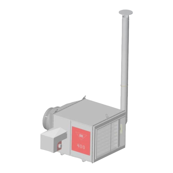
The suction opening of the 200-300 kW range heaters’ blowers can be turned to the opposite side. De- spite being turned, the elevation of the suction opening and the outlet connector will remain the same. The blower cone must also be turned with the blower. - Page 9 C-model heater. Available with different options; the orientation of the burner can be selected freely. Image: the C-model heater. Agrosec Hipress Agrosec Vacboost The handedness of the heaters; vacuum heaters and positive pressure heaters Antti-Teollisuus Oy 408100 11-2016...
-
Page 10: Spare Part Drawing 200
Vulcan M10 Dryer Heater Spare part drawing 200 Spare part drawing 200 Antti-Teollisuus Oy 408100 11-2016... - Page 11 HEATER JACKET LOWER 200 KW 10 A72557 68.2 A72562 HEATER JACKET UPPER 200 KW 10 A72562 37.9 A72565 HEATER JACKET SIDE BURNER 200 KW 10 A72565 15.6 A72566 HEATER JACKET SIDE FLUE 200 KW 10 A72566 30.3 A72490 HEATER EXCHANGER 200 KW 10...
-
Page 12: Spare Part Drawing 300
Vulcan M10 Dryer Heater Spare part drawing 300 Spare part drawing 300 Antti-Teollisuus Oy 408100 11-2016... - Page 13 SOCKET SCREW M6X70 AM 110530 NUT M6 DIN 934 A72543 HEATER EXPLOSION HATCH 200-500 KW 10 A72543 A72674 HEATER SUCTION NET ATTACH SHORT 200-500 KW M10 in vacuum A72674 heater A72675 HEATER SUCTION NET ATTACH SHORT 200-500 KW M10 in vacuum A72675 heater...
-
Page 14: Spare Part Drawing 400
Vulcan M10 Dryer Heater Spare part drawing 400 Spare part drawing 400 Antti-Teollisuus Oy 408100 11-2016... - Page 15 HEATER JACKET SIDE FLUE 400 KW 10 A72522 A72486 HEATER EXCHANGER 400 KW 10 A72486 207.3 A72538 HEATER OUTLET CONE 200-500 KW 10 A72538 43.3 508418 ADAPTER FOR AIR DUCT D630/800 A/J 31904 A72547 HEATER BLOWER CONE 400 KW M10...
-
Page 16: Spare Part Drawing 500
Vulcan M10 Dryer Heater Spare part drawing 500 Spare part drawing 500 Antti-Teollisuus Oy 408100 11-2016... - Page 17 HEATER JACKET SIDE FLUE 500 KW 10 A72522 A72486 HEATER EXCHANGER 500 KW 10 A72486 207.3 A72538 HEATER OUTLET CONE 200-500 KW 10 A72538 43.3 508418 ADAPTER FOR AIR DUCT D630/800 A/J 31904 A72547 HEATER BLOWER CONE 500 KW M10...
-
Page 18: Spare Part Drawing 700
Vulcan M10 Dryer Heater Spare part drawing 700 Spare part drawing 700 Antti-Teollisuus Oy 408100 11-2016... - Page 19 42251 GRAIN PIPE BAND 2-PART L/L D250 42251 104243 SOCKET SCREW M6X70 AM 110530 NUT M6 DIN 934 A72543 HEATER EXPLOSION HATCH 200-500 KW 10 A72543 A72140 DR HEATER TUBUL SUCT NET A1000 in vacuum A72140 heater 115550 GLASS FIBRE BAND 6X15 MM...
-
Page 20: Spare Part Drawing 1000
Vulcan M10 Dryer Heater Spare part drawing 1000 Spare part drawing 1000 Antti-Teollisuus Oy 408100 11-2016... - Page 21 42251 GRAIN PIPE BAND 2-PART L/L D250 42251 104243 SOCKET SCREW M6X70 AM 110530 NUT M6 DIN 934 A72543 HEATER EXPLOSION HATCH 200-500 KW 10 A72543 A72140 DR HEATER TUBUL SUCT NET A1000 in vacuum A72140 heater 115550 GLASS FIBRE BAND 6X15 MM...
-
Page 22: Spare Part Drawing, Outlet Cone 700/1000 A72163
Vulcan M10 Dryer Heater Spare part drawing, outlet cone 700/1000 A72163 Spare parts drawing A72163 Antti-Teollisuus Oy 408100 11-2016... - Page 23 A73083 DRYER HEATER TUBE CONE SUPPORT STRIP 1000/700 M10 A73083-0 6.09 503017 DRYER HEATER LIFTING LUG PL4X150X160 30DEG 41170-D 0.48 101810 HEX BOLT ZN 8X16 DIN933 0.01 111562 WASHER ZN 9/28X3 DIN440R 0.01 A72163 cone assembled Antti-Teollisuus Oy 408100 11-2016...
- Page 24 Vulcan M10 Dryer Heater Antti-Teollisuus Oy 408100 11-2016...
-
Page 25: Assembly Drawing, Outlet Cone 700/1000 A72163
Glue the ceramic sealing band onto the connecting flange of the heater before installing the cone into place. Antti-Teollisuus Oy 408100 11-2016... -
Page 26: Spare Part Drawing 1400
Vulcan M10 Dryer Heater Spare part drawing 1400 Antti-Teollisuus Oy 408100 11-2016... - Page 27 GRAIN PIPE BAND 2-PART L/L D250 42251 104243 SOCKET SCREW M6X70 AM 104243 110530 NUT M6 DIN 934 110530 A72543 HEATER EXPLOSION HATCH 200-500 KW 10 A72543 A75034 DR HEATER TUBUL SUCT NET 2000 M14 A75034 12.5 115550 GLASS FIBRE BAND 6X 15 MM 115550...
-
Page 28: Spare Part Drawing 2000
Vulcan M10 Dryer Heater Spare part drawing 2000 Antti-Teollisuus Oy 408100 11-2016... - Page 29 GRAIN PIPE BAND 2-PART L/L D250 42251 104243 SOCKET SCREW M6X70 AM 104243 110530 NUT M6 DIN 934 110530 A72543 HEATER EXPLOSION HATCH 200-500 KW 10 A72543 A75034 DR HEATER TUBUL SUCT NET 2000 M14 A75034 12.5 115550 GLASS FIBRE BAND 6X 15 MM 115550...
-
Page 30: Spare Part Drawing, Outlet Cone 1400/2000 A75038
Vulcan M10 Dryer Heater Spare part drawing, outlet cone 1400/2000 A75038 Antti-Teollisuus Oy 408100 11-2016... - Page 31 0.01 110540 NUT M8 DIN 934 107720 SCREW SELF-TAP 6K 4,8X13 ZN 101810 HEX BOLT ZN 101810 0.01 8X16 DIN933 111562 WASHER M10 D34/D11X3 DIN440R ZN 0.01 115579 CERAMIC BAND KERABAND 3x9 0.01 A75038 cone assembled Antti-Teollisuus Oy 408100 11-2016...
-
Page 32: Assembly Drawing, Outlet Cone 1400/2000 A75038
Vulcan M10 Dryer Heater Assembly drawing, outlet cone 1400/2000 A75038 Antti-Teollisuus Oy 408100 11-2016... - Page 33 The sides shall be provided with midmost radiation shields (part 13). A ceramic seal strip shall be affixed to the attachment flange of the heater before installing the cone in place. Antti-Teollisuus Oy 408100...
-
Page 34: Installing The Shield On The 1400/2000 Burners
Vulcan M10 Dryer Heater Installing the shield on the 1400/2000 burners Antti-Teollisuus Oy 408100 11-2016... - Page 35 At the bottom, the dimension is about 153 mm. Fix both halves of the door, using self-tapping screws 4.8x13. Put the roof in place last, and fix it to the vertical beams by using M8x12 screws. Fix the upper edge, using self-tapping screws 4.8x13. Antti-Teollisuus Oy 408100 11-2016...
-
Page 36: Vulcan 200 And 300 Kw Dimension Drawing, Positive Pressure
Vulcan M10 Dryer Heater Vulcan 200 and 300 kW dimension drawing, Positive pressure Left-handed motor blower cone turned over A-model, 200 and 300 kW Left-handed motor blower cone turned over C-model, 200 and 300 kW Antti-Teollisuus Oy 408100 11-2016... -
Page 37: Vulcan 200 And 300 Kw Dimension Drawing, Vacuum
Vulcan M10 Dryer Heater Vulcan 200 and 300 kW dimension drawing, Vacuum A-model, 200 and 300 kW C-model, 200 and 300 kW Antti-Teollisuus Oy 408100 11-2016... -
Page 38: Vulcan 400 And 500 Kw Dimension Drawing, Positive Pressure
Vulcan 400 and 500 kW dimension drawing, Positive pressure D630 reducer is used in the 400 kW heater A-model, 400 and 500 kW D630 reducer is used in the 400 kW heater C-model, 400 and 500 kW Antti-Teollisuus Oy 408100 11-2016... -
Page 39: Vulcan 400 And 500 Kw Dimension Drawing, Vacuum
Vulcan 400 and 500 kW dimension drawing, Vacuum D630 reducer is used in the 400 kW heater A-model, 400 and 500 kW D630 reducer is used in the 400 kW heater C-model, 400 and 500 kW Antti-Teollisuus Oy 408100 11-2016... -
Page 40: Vulcan 700 Kw Dimension Drawing, Positive Pressure
Vulcan M10 Dryer Heater Vulcan 700 kW dimension drawing, Positive pressure A-model, 700 kW C-model, 700 kW Antti-Teollisuus Oy 408100 11-2016... -
Page 41: Vulcan 700 And 1000 Kw Dimension Drawing, Vacuum
Vulcan 700 and 1000 kW dimension drawing, Vacuum D1000 reducer is used in the 700 kW heater A-model, 700 and 1000 kW D1000 reducer is used in the 700 kW heater in the 1000 kW heater C-model, 700 and 1000 kW Antti-Teollisuus Oy 408100 11-2016... -
Page 42: Vulcan 1000 Kw Dimension Drawing, Positive Pressure
Vulcan M10 Dryer Heater Vulcan 1000 kW dimension drawing, Positive pressure A-model, 1000 kW C-model, 1000 kW Antti-Teollisuus Oy 408100 11-2016... -
Page 43: Vulcan 1400 And 2000 Kw Dimension Drawing, Vacuum
Vulcan 1400 and 2000 kW dimension drawing, Vacuum in the 2000 kW heater D1000 reducer is used in the 1400 kW heater A-model, 1400-2000 kW D1000 reducer is used in the 1400 kW heater C-model, 1400-2000 kW in the 2000 kW heater Antti-Teollisuus Oy 408100 11-2016... -
Page 44: Installation
Suction air for the positive pressure heater shall always be routed via a pipe from outside the heater room. The burner shall be provided with an unobstructed supply of combustion air at all times. Max 0,5 m AN EXAMPLE CONFIGURATION PROVIDING ADEQUATE SUPPLY OF AIR Antti-Teollisuus Oy 408100 11-2016... -
Page 45: Lifting The Dryer Heater Into Position
- The air piping between the dryer heater and the dryer is assembled of air piping parts. Standard pipes leaving from the heater Heater (kW) Pipe diameter (mm) Heater (kW) Pipe diameter (mm) 1000 1000 1250 1400 1000 2000 1250 Antti-Teollisuus Oy 408100 11-2016... -
Page 46: Grain Pocket In The Air Pipe
Finish the work by applying sealing mastic. Provide the outlet sleeve for the pipe at the grain pocket with a plug and, as necessary, ensure that it stays in position using self-tapping screws. Antti-Teollisuus Oy 408100... -
Page 47: Oil Burner And Pipes
The settings of the airflow to the burner given in the table are indicative only. Assign an oil burner fitter to more precise adjustment. NOTE! Do not provide the oil burner with over-sized nozzles or increase the oil pressure so high that the maximum oil amount permissible for the burner will be exceeded! Antti-Teollisuus Oy 408100 11-2016... -
Page 48: Locating The Sensors And Safety Devices On A Positive Pressure Heater
5. Temperature sensor for outlet air In vacuum dryers with two blowers, the sensors on the outlet side shall be installed in the lower air pipe (as required, the upper blower can be taken out of use). Antti-Teollisuus Oy 408100 11-2016... -
Page 49: Installing The Temperature Measuring Facility
Fix the installation flange at the hole in the pipe, using self-tapping screws (2). Insert the sensor of the temperature transmitter into the pipe through the installation flange, and tighten it in place with the lock screw (5) Antti-Teollisuus Oy 408100 11-2016... -
Page 50: Installing The Vacuum Sensor
2–3 of the change-over contact will be switched on, even if the air adjuster plate is in its minimum position. If the change-over switch is not switched on, the oil burner will not start. Antti-Teollisuus Oy 408100 11-2016... -
Page 51: Installing The Fire Thermostat
The fire thermostat shuts down all the operations of the dryer immediately after the pre-set temperature has been reached, for example, as a result of fire inside the dryer. The fire thermostat is delivered with the blowers. A fire thermostat is installed in every outlet pipe from the blower. Antti-Teollisuus Oy 408100 11-2016... -
Page 52: Installing The Constant Temperature Regulators In The Positive Pressure Heaters 700 And 1000 With Single Drive Motor
M12 Nyloc nut. The intermediate rod can be made from e.g. 30x30x3 angular profile or L-profile with 12 mm holes drilled at intervals L, which match the distance between the regulators. Note! Check that the controller flaps of both regulators move synchronously. Antti-Teollisuus Oy 408100 11-2016... -
Page 53: Operating Instructions For The Dryer Heater
Minimum amounts of oil at the maximum output of the blower. Heater model 1000 Min. oil volume kg/h Antti-Teollisuus Oy 408100 11-2016... -
Page 54: Servicing
- Ensure that the inlet air piping to the dryer is clean. Some runoff of grain from the dryer may have occurred in connection with filling. Empty the grain pocket - Always test the operation of the limit switch for the heater room door before the drying season. Antti-Teollisuus Oy 408100 11-2016... -
Page 55: Service During The Operation
A prerequisite for validity of the guarantee is that the instructions issued by the manufacturer and the valid regula- tions have been followed during installation, use and service of the dryer heater. All matters related to the guarantee shall be agreed upon with the manufacturer before any action is taken. Antti-Teollisuus Oy 408100 11-2016... -
Page 56: Malfunctions During Operation
No flame is formed No spark Check the ignition wires and tips (transformer) ▼ Malfunction of the burner, signal light Fuse has tripped Check and reset the fuse, if neces- illuminates sary. Find out the fault Antti-Teollisuus Oy 408100 11-2016... - Page 57 Check and adjust the oil pressure Flue pipe blocked or damaged Check the pipe Burner blower impeller slips on Check and tighten the shaft Coupling ends of oil pump worn Change coupling ends of the shaft Antti-Teollisuus Oy 408100 11-2016...
- Page 58 Net for cooler fan of the engine Clean off dust blocked Motor of the blower unit overheats Cooling ribs blocked Clean off dust Blower unit does not start Engine safety switch has gone Reset engine safety switch Antti-Teollisuus Oy 408100 11-2016...
- Page 59 10 gal 80° 12 gal 60° To reset the malfunction in the burner, press the burner relay button with the malfunction light at the side of the burner. 1 kg of fuel oil equals to 1.18 litres Antti-Teollisuus Oy 408100 11-2016...
-
Page 60: Eu Declaration Of Conformity
Tel.: +358 2 7744700 Fax +358 2 7744777 declares that VULCAN M10 – DRYER HEATERS 200, 300, 400, 500, 700, 1000, 1400 and 2000 conform with the provisions of the following directives: - Machine Directive 2006/42/EU - Low Voltage Directive 2006/95/EU - Electro-Magnetic Compatibility Directive (EMC) 2004/108/EU Kuusjoki 11.01.2010...
Need help?
Do you have a question about the 200 and is the answer not in the manual?
Questions and answers