Table of Contents
Advertisement
Quick Links
Проконсультироваться и купить данное оборудование вы можете в компании «АНД-Системс»
адрес: 125480, г.Москва, ул.Туристская, д.33/1; site: https://andpro.ru тел: +7 (495) 545-4870 email: info@andpro.ru
При обращении используйте промокод AND-PDF и получите скидку.
SC826 S
E
S
toRAgE
NCLoSURE
ERiES
SC826BE1C-R741JBOD
SC826BE2C-R741JBOD
USER'S MANUAL
Revision 1.0
Advertisement
Table of Contents

Summary of Contents for Supercmicro SC826BE1C-R741JBOD
- Page 1 Проконсультироваться и купить данное оборудование вы можете в компании «АНД-Системс» адрес: 125480, г.Москва, ул.Туристская, д.33/1; site: https://andpro.ru тел: +7 (495) 545-4870 email: info@andpro.ru При обращении используйте промокод AND-PDF и получите скидку. SC826 S toRAgE NCLoSURE ERiES SC826BE1C-R741JBOD SC826BE2C-R741JBOD USER’S MANUAL Revision 1.0...
- Page 2 The information in this User’s Manual has been carefully reviewed and is believed to be accurate. The vendor assumes no responsibility for any inaccuracies that may be contained in this document, makes no commitment to update or to keep current the information in this manual, or to notify any person or organization of the updates.
-
Page 3: About This Manual
Preface Preface About this Manual This manual is written for professional system integrators and PC technicians. It provides information for the installation and use of the chassis. Installation and maintenance should be performed by experienced technicians only. This document lists compatible parts available when this document was published. Refer to the Supermicor web site for updates on supported parts and configurations This manual may be periodically updated without notice. -
Page 4: Table Of Contents
SC826 JBOD Chassis Manual Contents Chapter 1 Introduction ................1-1 Overview ......................1-1 Shipping List ....................1-1 Components ....................1-2 Drives ......................1-2 Power Supply ....................1-2 Cooling ......................1-2 Control Board ....................1-2 Mounting Rails ....................1-2 Where to get Replacement Components ............1-2 Returning Merchandise for Service.............. - Page 5 Preface Overheating ..................... 3-4 Drive Carrier LEDs ..................3-4 Power Supply LEDs ..................3-5 Chapter 4 Chassis Setup and Maintenance ........... 4-1 Overview ......................4-1 Removing the Power ..................4-2 Removing the Chassis Cover ................. 4-3 Installing Hard Drives ..................4-4 Removing a Hard Drive Carrier ..............
-
Page 6: Contacting Supermicro
SC826 JBOD Chassis Manual Contacting Supermicro Headquarters Address: Super Micro Computer, Inc. 980 Rock Ave. San Jose, CA 95131 U.S.A. Tel: +1 (408) 503-8000 Fax: +1 (408) 503-8008 Email: marketing@supermicro.com (General Information) support@supermicro.com (Technical Support) Web Site: www.supermicro.com Europe Address: Super Micro Computer B.V. -
Page 7: Chapter 1 Introduction
Chapter 1: Introduction Chapter 1 Introduction Overview The SC826B JBOD storage enclosure Is designed to scale your Supermicro server storage expansion capacity. In a 2U form factor, it offers twelve hot-swappable 3.5" SAS/SATA hard drive bays, without compromising superior cooling capabilities. The SC826BE2C-R741JBOD model offers two expanders for high availability. -
Page 8: Components
SC826B JBOD Chassis Manual Components Drives The chassis supports twelve hot-swap 3.5" SAS or SATA hard disk drives in the front. The drives are supported by a backplane. Power Supply The chassis features two redundant digital power supplies, each 740 Watts with a Platinum 80-Plus efficiency certification level. - Page 9 Chapter 1 Introduction the shipping carton, and mailed prepaid or hand-carried. Shipping and handling charges will be applied for all orders that must be mailed when service is complete. For faster service, RMA authorizations may be requested online (http://www. supermicro.com/support/rma/). Whenever possible, repack the chassis in the original Supermicro carton, using the original packaging material.
-
Page 10: Contacting Supermicro
SC826B JBOD Chassis Manual Contacting Supermicro Headquarters Address: Super Micro Computer, Inc. 980 Rock Ave. San Jose, CA 95131 U.S.A. Tel: +1 (408) 503-8000 Fax: +1 (408) 503-8008 Email: marketing@supermicro.com (General Information) support@supermicro.com (Technical Support) Web Site: www.supermicro.com Europe Address: Super Micro Computer B.V. -
Page 11: Chapter 2 Standardized Warning Statements For Ac Systems
Chapter 2: Warning Statements for AC Systems Chapter 2 Standardized Warning Statements for AC Systems About Standardized Warning Statements The following statements are industry standard warnings, provided to warn the user of situations which have the potential for bodily injury. Should you have questions or experience difficulty, contact Supermicro's Technical Support department for assistance. - Page 12 SC826 JBOD Chassis Manual Warnung WICHTIGE SICHERHEITSHINWEISE Dieses Warnsymbol bedeutet Gefahr. Sie befinden sich in einer Situation, die zu Verletzungen führen kann. Machen Sie sich vor der Arbeit mit Geräten mit den Gefahren elektrischer Schaltungen und den üblichen Verfahren zur Vorbeugung vor Unfällen vertraut.
- Page 13 Chapter 2: Warning Statements for AC Systems جسذٌة اصابة ًتتسبب ف حالة ٌوكي أى ًاًك ف خطز ًٌٌع هذا الزهز !تحذٌز الذوائز بالوخاطز الٌاجوة عي ي على علن ، ك هعذات تعول على أي قبل أى الكهزبائٍة حىادث أي وقىع وٌع...
-
Page 14: Installation Instructions
SC826 JBOD Chassis Manual Installation Instructions Warning! Read the installation instructions before connecting the system to the power source. 設置手順書 システムを電源に接続する前に、 設置手順書をお読み下さい。 警告 将此系统连接电源前,请先阅读安装说明。 警告 將系統與電源連接前,請先閱讀安裝說明。 Warnung Vor dem Anschließen des Systems an die Stromquelle die Installationsanweisungen lesen. ¡Advertencia! Lea las instrucciones de instalación antes de conectar el sistema a la red de alimentación. -
Page 15: Circuit Breaker
Chapter 2: Warning Statements for AC Systems Circuit Breaker Warning! This product relies on the building's installation for short-circuit (overcurrent) protection. Ensure that the protective device is rated not greater than: 250 V, 20 A. サーキッ ト ・ ブレーカー この製品は、 短絡 (過電流) 保護装置がある建物での設置を前提としています。 保護装置の定格が250 V、... -
Page 16: Power Disconnection Warning
SC826 JBOD Chassis Manual 경고! 이 제품은 전원의 단락(과전류)방지에 대해서 전적으로 건물의 관련 설비에 의존합니다. 보호장치의 정격이 반드시 250V(볼트), 20A(암페어)를 초과하지 않도록 해야 합니다. Waarschuwing Dit product is afhankelijk van de kortsluitbeveiliging (overspanning) van uw electrische installatie. Controleer of het beveiligde aparaat niet groter gedimensioneerd is dan 220V, 20A. - Page 17 Chapter 2: Warning Statements for AC Systems auf den Chassisinnenraum zurückgreift, um Systemsbestandteile anzubringen oder zu entfernen. ¡Advertencia! El sistema debe ser disconnected de todas las fuentes de energía y del cable eléctrico quitado de los módulos de fuente de alimentación antes de tener acceso el interior del chasis para instalar o para quitar componentes de sistema.
-
Page 18: Equipment Installation
SC826 JBOD Chassis Manual Equipment Installation Warning! Only trained and qualified personnel should be allowed to install, replace, or service this equipment. 機器の設置 トレーニングを受け認定された人だけがこの装置の設置、 交換、 またはサービスを許可 されています。 警告 只有经过培训且具有资格的人员才能进行此设备的安装、更换和维修。 警告 只有經過受訓且具資格人員才可安裝、更換與維修此設備。 Warnung Das Installieren, Ersetzen oder Bedienen dieser Ausrüstung sollte nur geschultem, qualifiziertem Personal gestattet werden. -
Page 19: Restricted Area
Chapter 2: Warning Statements for AC Systems Waarschuwing Deze apparatuur mag alleen worden geïnstalleerd, vervangen of hersteld door geschoold en gekwalificeerd personeel. Restricted Area Warning! This unit is intended for installation in restricted access areas. A restricted access area can be accessed only through the use of a special tool, lock and key, or other means of security. -
Page 20: Battery Handling
SC826 JBOD Chassis Manual אזור עם גישה מוגבלת !אזהרה יש להתקין את היחידה באזורים שיש בהם הגבלת גישה. הגישה ניתנת בעזרת .)'כלי אבטחה בלבד (מפתח, מנעול וכד محظورة مناطق ٍنتركُبها ف هذه انىحذة تخصيص تم ،أداة خاصت من خالل استخذاو فقط... - Page 21 Chapter 2: Warning Statements for AC Systems Warnung Bei Einsetzen einer falschen Batterie besteht Explosionsgefahr. Ersetzen Sie die Batterie nur durch den gleichen oder vom Hersteller empfohlenen Batterietyp. Entsorgen Sie die benutzten Batterien nach den Anweisungen des Herstellers. Attention Danger d'explosion si la pile n'est pas remplacée correctement. Ne la remplacer que par une pile de type semblable ou équivalent, recommandée par le fabricant.
-
Page 22: Redundant Power Supplies
SC826 JBOD Chassis Manual Redundant Power Supplies Warning! This unit might have more than one power supply connection. All connections must be removed to de-energize the unit. 冗長電源装置 このユニッ トは複数の電源装置が接続されている場合があります。 ユニッ トの電源を切るためには、 すべての接続を取り外さなければなりません。 警告 此部件连接的电源可能不止一个,必须将所有电源断开才能停止给该部件供电。 警告 此裝置連接的電源可能不只一個,必須切斷所有電源才能停止對該裝置的供電。 Warnung Dieses Gerät kann mehr als eine Stromzufuhr haben. Um sicherzustellen, dass der Einheit kein trom zugeführt wird, müssen alle Verbindungen entfernt werden. -
Page 23: Backplane Voltage
Chapter 2: Warning Statements for AC Systems امداد الطاقة بوحدات عدة اتصاالت جهاز ال يكون لهذا قد الكهرباء عن وحدة ال لعسل كافة االتصاالت يجب إزالة 경고! 이 장치에는 한 개 이상의 전원 공급 단자가 연결되어 있을 수 있습니다. 이 장치에 전원을... -
Page 24: Comply With Local And National Electrical Codes
SC826 JBOD Chassis Manual מתח בפנל האחורי !הרה אז קיימת סכנת מתח בפנל האחורי בזמן תפעול המערכת. יש להיזהר במהלך .העבודה اللىحة أوالطاقة المىجىدة على التيار الكهزبائي مه خطز هناك هذا الجهاس خدمة كه حذرا عند يعمل النظام عندما يكىن 경고! 시스템이... -
Page 25: Product Disposal
Chapter 2: Warning Statements for AC Systems Attention L'équipement doit être installé conformément aux normes électriques nationales et locales. תיאום חוקי החשמל הארצי !אזהרה הציוד חייבת להיות תואמת לחוקי החשמל המקומיים והארציים התקנת المتعلقة المحلية والىطىية قىاويه يجب أن يمتثل لل الكهربائية... -
Page 26: Hot Swap Fan Warning
SC826 JBOD Chassis Manual ¡Advertencia! Al deshacerse por completo de este producto debe seguir todas las leyes y reglamentos nacionales. Attention La mise au rebut ou le recyclage de ce produit sont généralement soumis à des lois et/ou directives de respect de l'environnement. Renseignez-vous auprès de l'organisme compétent. - Page 27 Chapter 2: Warning Statements for AC Systems 警告 當您從機架移除風扇裝置,風扇可能仍在轉動。小心不要將手指、螺絲起子和其他 物品太靠近風扇。 Warnung Die Lüfter drehen sich u. U. noch, wenn die Lüfterbaugruppe aus dem Chassis genommen wird. Halten Sie Finger, Schraubendreher und andere Gegenstände von den Öffnungen des Lüftergehäuses entfernt. ¡Advertencia! Los ventiladores podran dar vuelta cuando usted quite ell montaje del ventilador del chasis.
-
Page 28: Power Cable And Ac Adapter
SC826 JBOD Chassis Manual Power Cable and AC Adapter Warning! When installing the product, use the provided or designated connection cables, power cables and AC adaptors. Using any other cables and adaptors could cause a malfunction or a fire. Electrical Appliance and Material Safety Law prohibits the use of UL or CSA -certified cables (that have UL/CSA shown on the code) for any other electrical devices than products designated by Supermicro only. - Page 29 Chapter 2: Warning Statements for AC Systems Attention Lors de l'installation du produit, utilisez les bables de connection fournis ou désigné. L'utilisation d'autres cables et adaptateurs peut provoquer un dysfonctionnement ou un incendie. Appareils électroménagers et de loi sur la sécurité Matériel interdit l'utilisation de UL ou CSA câbles certifiés qui ont UL ou CSA indiqué...
- Page 30 SC826 JBOD Chassis Manual Notes 2-20...
-
Page 31: Chapter 3 System Interface
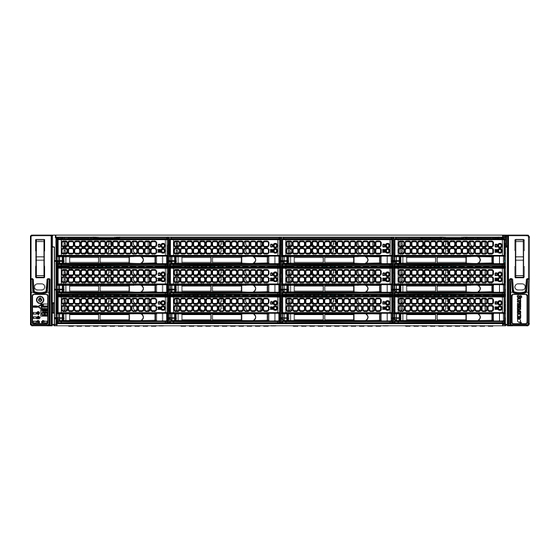
Chapter 3: System Interface Chapter 3 System Interface Overview The chassis includes a control panel on the front that houses power buttons and status monitoring lights. The externally accessible hard drives display status lights. The power supply displays status lights visible from the back of the chassis. Figure 3-1. -
Page 32: Control Panel Buttons
SC826 JBOD Chassis Manual Control Panel Buttons The chassis includes two push-buttons that control the system. Power The main power switch applies or removes primary power from the power supply to the server but maintains standby power. To perform most maintenance tasks, unplug the system to remove all power.. -
Page 33: Information Led
Chapter 3: System Interface Power Fail Indicates a power supply module has failed. Information LED Alerts operator to several states, as noted in the table below. Information LED Status Description An overheat condition has occured. Continuously on and red (This may be caused by cable congestion.) Blinking red (1Hz) Fan failure, check for an inoperative fan. -
Page 34: Drive Carrier Leds
SC826 JBOD Chassis Manual Drive Carrier LEDs The chassis includes externally accessible SAS/SATA drives. Each drive carrier displays two status LEDs on the front of the carrier. LED Color Blinking Pattern Behavior for Device Activity LED Blue Blinking I/O activity Blue Solid On Idle SAS/NVMe drive installed... -
Page 35: Chapter 4 Chassis Setup And Maintenance
Chapter 4: Chassis Setup and Maintenance Chapter 4 Chassis Setup and Maintenance Overview This chapter covers the steps required to install components and perform maintenance on the chassis. The only tool required is a Phillips screwdriver. Review the warnings and precautions listed in the manual before setting up or servicing this chassis. - Page 36 SC826 JBOD Chassis Manual Power Up/Power Down Sequences There are several procedures to turn on or off the system with the CB3 JBOD control board. Power Up First Use or Power Cord Plug-In 1. Plug the power cords into the rear of the power supplies. 2.
-
Page 37: Cable Connections
Chapter 4: Chassis Setup and Maintenance Removing Power from the System Before performing most setup or maintenance tasks, use the following procedure to ensure that power has been removed from the system. 1. After the system has completely shut-down, carefully grasp the head of the power cord and gently pull it out of the back of the power supply. -
Page 38: Sas Cables
SC826 JBOD Chassis Manual SAS Cables This drawing shows connectors for SAS cabling. For primary and secondary, the top two connectors are marked In, and the bottom two connectors are marked In/Out. Connect two mini-SAS HD cables (SFF-8644) from the head server node host bus adapter (HBA) card to the top two Primary receptacles marked In. - Page 39 Chapter 4: Chassis Setup and Maintenance Cascading Storage The following diagram shows a server with a single host bus adapter (HBA) and requires only the primary expander on the backplane. The SC826 JBOD storage enclosure model E1C can accomodate this configuration. Server with Single Host Bus Adapter (HBA) External Mini-SAS HD Cable...
- Page 40 SC826 JBOD Chassis Manual The following diagram shows a server with dual HBAs and requires the primary and secondary expanders on the backplane. The SC826 JBOD storage enclosure model E2C accomodates this configuration. Server with Dual Host Bus Adapters (HBAs) External Mini-SAS HD Cable SC826 JBOD SC826 JBOD...
-
Page 41: Removing The Chassis Cover
Chapter 4: Chassis Setup and Maintenance Removing the Chassis Cover Figure 4-3. Removing the Chassis Cover Removing the Chassis Cover 1. Power down the server as descrbed in section 4-2, lay the chassis on a flat stable surface and remove the chassis cover. 2. -
Page 42: Installing Hard Drives
SC826 JBOD Chassis Manual Installing Hard Drives The SC826 JBOD chassis supports twelve hot-swappable 3.5" hard drives, which may be removed without powering-down the system. The drives are mounted in drive carriers to simplify their installation and removal from the chassis. These carriers also help promote proper airflow for the drive bays. -
Page 43: Installing Hard Drives
Chapter 4: Chassis Setup and Maintenance Installing Hard Drives Caution: Except for short periods of time (swapping hard drives), do not operate the server with the hard drive bays empty. Note: Your operating system must have RAID support to enable the hot-swap capability of the drives. - Page 44 SC826 JBOD Chassis Manual SAS/SATA Hard Drive Hard Drive Carrier Use a hard, stable surface when installing the hard drive Figure 4-7. Installing a Drive into the Carrier Installing a Hard Disk Drive 1. Remove the two screws connecting the dummy drive to the carrier. 2.
-
Page 45: System Fans
Chapter 4: Chassis Setup and Maintenance System Fans In most cases, the chassis power supply and fans are pre-installed. Procedures to replace them follow. Three heavy-duty fans provide cooling for the chassis. Release Tab Figure 4-8. System Fan Replacing a System Fan 1. - Page 46 SC826 JBOD Chassis Manual Figure 4-9. Placing the System Fan in the Chassis 4-12...
-
Page 47: Power Supply
Chapter 4: Chassis Setup and Maintenance Power Supply The system has two redundant, hot-swap power supply modules. They automatically sense the input voltage between 100v to 240v, and operate at that voltage. An amber light on the power supply is illuminated when the power is switched off. An green light indicates that the power supply is operating. -
Page 48: Power Distributor
SC826 JBOD Chassis Manual Figure 4-11. Replacing the Power Distributor Power Distributor Chassis that are 2U or more in height require a power distributor. The power distributor provides failover and power supply redundancy. Changing the Power Distributor 1. Power down the server as described in section 4-1, lay the chassis on a flat, stable surface and remove the chassis cover. -
Page 49: Control Board
Chapter 4: Chassis Setup and Maintenance Control Board The JBOD control board (CSE-PTJBOD-CB3) allows the user to remotely control and monitor the chassis resources using IPMI, such as powering on or off, controlling fan speeds and reading temperature data from the backplane. The location is shown in the figure below. -
Page 50: Backplane
SC826 JBOD Chassis Manual Backplane The backplane is located behind the hard drives and in front of the front system fans. In order to change jumper settings on the backplane, it may be necessary to remove the backplane from the chassis. Removing the Backplane from the Chassis 1. - Page 51 Chapter 4: Chassis Setup and Maintenance 5. Loosen the three screws in the spring bar, located on the floor of the chassis, indicated by the arrows below. 6. Gently ease the backplane up and out of the chassis. 4-17...
- Page 52 SC826 JBOD Chassis Manual Installing the Backplane into the Chassis 1. Power down the system as described in Section 4-2 and open the chassis cover. 2. Ensure that all of the hard drive carriers have been removed from the bays in the front of the chassis and that the spring bar has been loosened as directed in the previous section.
-
Page 53: Chapter 5 Chassis Installation
Chapter 5: Chassis Installation Chapter 5 Chassis Installation This chapter provides instructions for preparing and mounting your chassis in a rack. Unpacking the System You should inspect the box the chassis was shipped in and note if it was damaged in any way. -
Page 54: Warnings And Precautions
SC826 JBOD Chassis Manual Warnings and Precautions Rack Precautions • Ensure that the leveling jacks on the bottom of the rack are fully extended to the floor with the full weight of the rack resting on them. • In single rack installation, stabilizers should be attached to the rack. In multiple rack installations, the racks should be coupled together. -
Page 55: Rack Mounting Considerations
Chapter 5: Chassis Installation Rack Mounting Considerations Ambient Operating Temperature If installed in a closed or multi-unit rack assembly, the ambient operating temperature of the rack environment may be greater than the ambient temperature of the room. Therefore, consideration should be given to installing the equipment in an environment compatible with the manufacturer’s maximum rated ambient temperature (Tmra). -
Page 56: Installing The System Into A Rack
SC826 JBOD Chassis Manual Installing the System into a Rack This section provides information on installing the server into a rack unit with the rack rails provided. There are a variety of rack units on the market, so the assembly procedure may differ slightly. -
Page 57: Releasing The Inner Rail
Chapter 5: Chassis Installation Releasing the Inner Rail Each inner rail has a locking latch. This latch prevents the server from coming completely out of the rack when when the chassis is pulled out for servicing. To mount the rail onto the chassis, first release the inner rail from the outer rails. Releasing Inner Rail from the Outer Rails 1. -
Page 58: Installing The Inner Rails On The Chassis
SC826 JBOD Chassis Manual Installing the Inner Rails on the Chassis Installing the Inner Rails 1. Identify the left and right inner rails. They are labeled. 2. Place the inner rail firmly against the side of the chassis, aligning the hooks on the side of the chassis with the holes in the inner rail. -
Page 59: Installing The Outer Rails Onto The Rack
Chapter 5: Chassis Installation Installing the Outer Rails onto the Rack Installing the Outer Rails 1. Press upward on the locking tab at the rear end of the middle rail. 2. Push the middle rail back into the outer rail. 3. -
Page 60: Sliding The Chassis Onto The Rack Rails
SC826 JBOD Chassis Manual Sliding the Chassis onto the Rack Rails Warning: Mounting the system into the rack requires at least two people to support the chassis during installation. Please follow safety recommendations printed on the rails. Installing the Chassis into a Rack 1. -
Page 61: Appendix A Sc826 Jbod Power Supply Specifications
Appendix A Power Supply Specifications Appendix A SC826 JBOD Power Supply Specifications This appendix lists power supply specifications for the SC826 JBOD chassis. -R741 Model 740W MFR Part # PWS-741P-1R with PDB AC Input 100-240 V, 4.5-11 Amp, 50-60 Hz DC Output +12V 63 Amp +5V standby 4 Amp... - Page 62 SC826 JBOD Chassis Manual Notes...
-
Page 63: Appendix B Bpn-Sas3-826El Backplane Specifications
BPN-SAS3-826EL Backplane Specifications B-1 Overview of the SAS3-826EL1/EL2 Backplanes This appendix provides details about the backplanes used in the SC826 JBOD chassis. Chassis Model Backplane Feature SC826BE1C-R741JBOD BPN-SAS3-826EL1 Single SAS expander SC826BE2C-R741JBOD BPN-SAS3-826EL2 Dual SAS expanders B-2 Safety Guidelines ESD Safety Electrostatic Discharge (ESD) can damage electronic com ponents. - Page 64 SC826 JBOD Chassis Manaual • Disconnect the power cable before installing or removing any cables from the backplane. • Make sure that the backplane is securely and properly installed on the motherboard to prevent damage to the system due to power shortage. B-3 Version Information The BPN-SAS3-826EL backplane has been designed to utilize the most up-to-date technology available, providing your system with reliable, high-quality performance.
- Page 65 Appendix B BPN-SAS3-826EL Backplane Specifications B-4 Rear Connectors LED28 HB-LED PRI-SDB DESIGNED IN USA LED29 C502 I2C#4 I2C#0 LED25 LED26 BPN-SAS3-826EL1 SEC-UART PRI-UART SAS CODE C496 C497 SEC-SDB REV:1.00 SAS CODE C501 C495 ACT-LED SECONDARY EXPANDER C494 C492 C498 TEST C499 PRIMARY EXPANDER JPW3...
- Page 66 SC826 JBOD Chassis Manaual B-5 Rear Connector and Pin Definitions 1-2. Primary and Secondary Expander Chips The primary and secondary expander chips allow the backplane to support dual port, cascading, and failover configurations. 3. Backplane Main Power Connectors Backplane Main Power The 4-pin connectors, designated JPW1, 4-Pin Connector JPW2, and JPW3, provide power to the...
-
Page 67: Explanation Of Jumpers
Appendix B BPN-SAS3-826EL Backplane Specifications B-6 Rear Jumper Location and Settings HB-LED PRI-SDB LED28 C502 DESIGNED IN USA LED29 I2C#4 I2C#0 LED25 LED26 BPN-SAS3-826EL1 SEC-UART SAS CODE PRI-UART C496 C497 SEC-SDB REV:1.00 SAS CODE C501 C495 ACT-LED SECONDARY EXPANDER C494 C492 C498 TEST... - Page 68 SC826 JBOD Chassis Manaual B-7 Rear LED Indicators HB-LED HB-LED (J28) LED27 (J29) HB-LED PRI-SDB LED28 C502 I2C#4 DESIGNED IN USA LED29 I2C#0 LED25 LED26 BPN-SAS3-826EL1 SEC-UART SAS CODE PRI-UART C496 C497 SEC-SDB REV:1.00 SAS CODE C501 C495 ACT-LED SECONDARY EXPANDER C494 C492 C498...
- Page 69 Appendix B BPN-SAS3-826EL Backplane Specifications B-8 Front Connectors and LED Indicators LED3 LED6 LED9 LED12 LED15 LED21 LED18 LED24 C581 DRV#12 DRV#6 DRV#3 DRV#12 DRV#6 DRV#9 DRV#3 DRV#9 C173 C172 LED5 LED8 LED2 C171 LED11 C170 C158 C159 C161 C160 LED14 LED17 LED20...
-
Page 70: Dual Port And Cascading Configurations
SC826 JBOD Chassis Manaual Dual Port and Cascading Configurations B-9 Single and Dual Port Expanders SAS connectors PRI-J1 to J4 and SEC-J1 to J4 are bidirectional and can be treated as input or output. Single Ports BPN-SAS3-826EL1 backplanes have a single port expander that accesses all of the drives and supports cascading. - Page 71 Appendix B BPN-SAS3-826EL Backplane Specifications Connecting an Internal HBA to the Backplane This section shows connections and cables that connect an internal HBA to the backplane. Note: Not applicable for the SC826 JBOD chassis. HB-LED PRI-SDB LED28 DESIGNED IN USA LED29 C502 I2C#4...
- Page 72 SC826 JBOD Chassis Manaual Supported Internal HBA Cables Use the following cables to create connections between the internal HBA and BPN-SAS3-826EL backplane. The cables required depend upon the HBA connector. Cable Name: Internal iPass (Mini-SAS) to HD (Mini-SAS) Part #: CBL-SAST-0508-01 Length: 50 cm (19 inches) Part #: CBL-SAST-0507-01 Length: 80 cm (31 inches)
- Page 73 Appendix B BPN-SAS3-826EL Backplane Specifications B-10 Failover The BPN-SAS3-826EL2 model backplane has two expanders which enable effective failover and recovery. Single Host Bus Adapter SAS HBA In a single host bus configuration, the backplane connects to one host bus adapter. PRI-J4 LED28 HB-LED...
- Page 74 SC826 JBOD Chassis Manaual Failover with RAID Cards and Multiple HBAs The BPN-SAS3-826EL backplane may be configured for failover with multiple HBAs using either RAID controllers or HBAs to acheive failover protection. RAID Controllers: If RAID controllers are used, then the failover is accomplished through port failover on the same RAID card.
- Page 75 Appendix B BPN-SAS3-826EL Backplane Specifications B-12 JBOD Control Board In a cascaded configuration, the first chassis includes a motherboard and at least one host bus adapter (HBA). Other storage enclosures in the system must be equipped with a JBOD control board. This board controls power and provides some mangement over the chassis components.
- Page 76 SC826 JBOD Chassis Manaual B-13 Connecting an External HBA to the Backplane This backplane supports external host bus adapters. In this configuration, the HBA and the backplane are in different physical chassis. This allows adding a JBOD storage enclosure to an existing system. Single External Host Bus Adapter PRI-J4 HB-LED...
- Page 77 Appendix B BPN-SAS3-826EL Backplane Specifications Cable and Adapter Figure B-17 External Mini-SAS HD to External Mini-SAS HD Cable Cable Name: 1 Meter External Mini-SAS HD to External Mini-SAS HD Cable Part #: CBL-SAST-0573 Ports: Single Placement: External Cable Description: External cascading cable, connects ports between servers and JBODs. Figure B-18.
- Page 78 SC826 JBOD Chassis Manaual Connecting Multiple Backplanes in a Single Channel Environment This section describes the cables used when cascading from a single HBA. These connections use CBL-SAST-0531 internal cables and CBL-SAST-0573 external cables. CBL-SAST-0531 (Internal Cable) LED28 HB-LED DESIGNED IN USA PRI-J4 LED29 PRI-SDB...
- Page 79 Appendix B BPN-SAS3-826EL Backplane Specifications Connecting Multiple Backplanes in a Dual Channel Environment This section describes the cables used when cascading from dual HBAs. These connections use CBL-SAST-0531 internal cables and CBL-SAST-0573 external cables. Port A Expander 1 Port B Expander 2 LED28 HB-LED PRI-SDB...
- Page 80 SC826 JBOD Chassis Manaual Notes B-18...
-
Page 81: Appendix C Cse-Ptjbod-Cb3 Control Board
Appendix C: CB3 JBOD Control Board Appendix C CSE-PTJBOD-CB3 Control Board C-1 Overview The CSE-PTJBOD-CB3 model JBOD control board allows the user to remotely control and monitor the chassis resources using IPMI, such as powering on or off, controlling fan speeds and reading temperature data from the backplane. It has been designed to utilize the most up-to-date technology available, providing your system with reliable, high-quality performance. -
Page 82: General Safety Guidelines
SC826 JBOD Chassis Manual General Safety Guidelines • Always disconnect power cables before installing or removing any components from the computer, including the control board. • Disconnect the power cable before installing or removing any cables from the control board. •... - Page 83 Appendix C: CB3 JBOD Control Board Component and Connector Definitions 1. BMC Chip The Baseboard Management Controller (BMC) chip monitors the physical state of a system and provides communication with the system administrator through an independent connection. 2. I C Connectors These connectors (JP1-JP4) accept cables for up to four SAS2/SAS3 backplanes that carry management data between the the backplane and the control board.
- Page 84 SC826 JBOD Chassis Manual 9. PMBus Connector This connector is designated JPI2C1 and connects the power distributor to the Power Management Bus (PMBus). 10. Fan Connectors The fan connectors supply power to the fans and are designated FAN1-FAN10. 11. ATX Power Connector The ATX power connector is designated JPW1.
- Page 85 Appendix C: CB3 JBOD Control Board FAN2 FAN4 FAN5 FAN6 FAN3 FAN10 FAN9 JPW1 1-2:SAS3 2-3:SAS2_847D NMI X PWR LED X NIC1 X OH/FF X RST ON PWR ON Figure CB3-3. LED Indicators LED Indicators Description Heartbeat LED: A blinking LED indicates BMC activity Power LED: DC power indicator...
- Page 86 SC826 JBOD Chassis Manual C-4 I C Cabling to the Backplane This JBOD storage enclosure is preconfigured with the internal cables connected. Use this section for reference if a cable becomes disconnected during maintenance. Ensure that the JP5 jumper on the JBOD control board is set according to the table in the section, Jumpers and LED Indicators.
- Page 87 Appendix C: CB3 JBOD Control Board C-5 JBOD Power Up/Power Down Sequences There are several procedures to turn on or off the system with the CB3 JBOD control board. Power Up First Use or Power Cord Plug-In 1. Plug the power cords into the rear of the power supplies. 2.
- Page 88 SC826 JBOD Chassis Manual C-6 IPMI Static IP to DHCP Setting IP Address to DHCP Setting 1. Download the utility from the Supermicro website or technical support. 2. Extract the file to a known folder. 3. By default, the JBOD control board will be configured in static IP 192.168.1.99. 4.
- Page 89 Appendix C: CB3 JBOD Control Board Notes...
- Page 90 SC826 JBOD Chassis Manual Notes Disclaimer (cont.) The products sold by Supermicro are not intended for and will not be used in life sup- port systems, medical equipment, nuclear facilities or systems, aircraft, aircraft devices, aircraft/emergency communication devices or other critical systems whose failure to per- form be reasonably expected to result in significant injury or loss of life or catastrophic property damage.
Need help?
Do you have a question about the SC826BE1C-R741JBOD and is the answer not in the manual?
Questions and answers