Table of Contents
Advertisement
Quick Links
Advertisement
Table of Contents

Summary of Contents for Motec Systems C185
- Page 1 C185 Combined Display Logger USER MANUAL...
- Page 2 MoTeC C185 User Manual Copyright © 2013 – MoTeC Pty Ltd The information in this document is subject to change without notice. While every effort is taken to ensure correctness, no responsibility will be taken for the consequences of any inaccuracies or omissions in this manual.
-
Page 3: Table Of Contents
C185 Dash Manager Software ..........14 i2 Data Analysis Software ............14 Telemetry Monitor Software ............. 15 Connecting the C185 to a PC ..........15 Configuration ................. 16 Configuration File ................16 Channels ..................... 17 ... - Page 4 Wire Specification ..............57 PC Connection ................. 58 CAN Bus Wiring Requirements ..........59 C185 to ECU wiring (RS232) ........... 60 Update Rate Summary ............... 62 Command line..................63 CAN Bus Bandwidth Limit ..............65 ...
-
Page 6: Introduction
Features The C185 comes with a range of features as standard and several options available as upgrades to customise and grow your system. These additional features are activated through a simple password acquired from MoTeC, at any time when you need it. - Page 7 • Windows-based software designed for setup and management of the display and data logging system • The user can generate a configuration file offline and then send the completed configuration to the C185 • Calculations including lap times, lap gain/loss, speed and distance, fuel prediction •...
-
Page 8: System Overview
#61132 Ethernet to Autosport pins cable, 1.8 m System Overview The C185 offers extensive possibilities to integrate with ECUs, peripheral devices and accessories to form a complete solution that powers, controls, logs, monitors and communicates virtually any automotive parameter. -
Page 9: Typical Devices Used With C185
The typical update rate is about 20 times per second for RS232 and 50 times per second for CAN. Sensors The C185 inputs can be connected to a wide variety of sensors. Different types of sensors are available to suit different types of measurements, for example: temperature, pressure, movement etc. - Page 10 Note: The E888 / E816 inputs have lower resolution than the VIM/SVIM inputs and have slower update rates. Accessories A BR2 Beacon Receiver may be connected to the C185, which allows the C185 to calculate lap times for display and to provide lap information for the data logging analysis software.
- Page 11 Introduction analysis of the data including maths calculations, while the vehicle is still on the track. Other telemetry features include: warning alarms, position of multiple vehicles on a track map, broadcast data via DDE (Dynamic Data Exchange) or via IP (Internet Protocol). Note: The Telemetry option is required for the basic functionality.
- Page 12 MoTeC Introduction Remote Displays A remote display device may be connected to the C185 to allow display of any value that the C185 calculates, such as lap times and warning alarm messages. The C185 supports D153, D175 displays which are connected via CAN.
-
Page 13: Installation
0 and 40 degrees. Display reflections should also be considered when determining the mounting angle. 20° The C185 uses a 79 pin Autosport connector. See Connector and Pin List by Pin Number for full details. Wiring Tips • To ensure that the connector is sealed, plug unused holes with filler plugs. -
Page 14: Connecting Devices
• Use the correct crimping tool for all contacts to ensure a reliable connection. • Power the C185 via a separate switch and a 5 ampere fuse, to ensure the PC can communicate with the C185 without the need to power the rest of the vehicle. - Page 15 Installation These inputs can also be used to measure two wire variable resistance sensors if an external pull-up resistor is connected from the input to the 5 V sensor supply. Additionally, on/off switch signals may be connected, which may also require an external pull-up resistor.
-
Page 16: Outputs
MoTeC Installation sensors varies with speed of rotation, variable trigger levels are required, which must vary with the frequency of the input signal. The Speed Inputs can also be used with Hall Effect type wheel speed sensors. The Pulse Width measurement method measures the high time of the pulse rather than the low time as measured by the Digital Inputs. - Page 17 CAN (Controller Area Network) Communications This protocol enables communication between all devices connected to the same bus. The CAN bus allows communicating at high speeds. The C185 has two independent CAN communications ports that can be connected to other devices with a compatible CAN port. The bus speed for each interface can be set independently.
-
Page 18: Connecting Devices Examples
Uses the Telemetry Communications: RS232 feature of the ECU to send data to the C185 ECU 'hundred series': Communications: Ensure the ECU and C185 (M400, M600, M800, are connected on the M880), M1 same CAN bus Telemetry Communications: Wiring is dependent on the... -
Page 19: Software Installation
• When downloading is finished, double click on the file and select run • Follow the instructions on the InstallShield Wizard • To start the program after installation, click the C185 Manager icon on the desktop or click Start > All Programs > MoTeC > C185 > C185 Dash... -
Page 20: Telemetry Monitor Software
• Enter the C185 serial number If the PC needs to communicate with more than one C185, repeat the steps. Only one connection can be active at a time. To switch to a different C185 select the appropriate connection and click Make Active. -
Page 21: Configuration
All changes to the C185 configuration are performed ‘Offline’, i.e. without the PC communicating with the C185. The changes are saved in the configuration file on the PC. The file must be sent to the C185 before the changes take effect. See Operation. -
Page 22: Channels
Channels Channels are used to convey information between the various systems of the C185. For example an input pin may feed a channel called ‘Fuel Pressure’. This channel may then be used by another system, such as the Display System or Data Logging systems. - Page 23 Configuration Channel Connection Example Sensors Analogue Speed Inputs Inputs Comms Data Logging Logging System Memory Display System Display Alarm System RS232 Telemetry Comms Gear Detection Auxiliary Warning Outputs Light Channels...
-
Page 24: Channel Properties
MoTeC Configuration Channel Properties Each channel has defined properties, some of which may be modified by the user. Predefining these properties makes the channels easy to use throughout the rest of the software. • Properties that may be modified by the user o Name The channel names (and abbreviations) may be changed if necessary. -
Page 25: Selecting Channels
Configuration Selecting Channels There are two methods of selecting channels, either the Category Method or the Search Method. Category Method This method divides all the channels into categories and sub categories, so that the list can be narrowed down to a small list of channels. For example, the ‘Engine Sensors / Cooling’... - Page 26 MoTeC Configuration Search Method This method lists all channels in alphabetical order and allows a channel to be found either by typing the first few letters of any word in the channel name, or by scrolling through the list. Note: The words may be typed out of order so that ‘Engine Oil Temp’ could be found by typing "temp eng oil"...
-
Page 27: Connections
Configuring Outputs • On the Connections menu, click Devices • Select device (e.g. C185) and then click the Output Pins tab to list all outputs available for this product Note: Some outputs require 52 I/O Upgrade to make them available. See C185 Upgrades. -
Page 28: Calculations
When MoTeC releases new products, new communication templates will also be released. These will be incorporated in the latest software versions. See Updating C185 Dash Manager Software on how to update to a new software version to make the latest communication templates available. -
Page 29: Functions
Refer to C185 Dash Manager online help for additional information. Power The C185 power can be turned off at any time without losing the logged data, because it uses FLASH memory that does not require an internal battery to keep it alive. - Page 30 Logging Rate The logging rate sets how often each channel is logged and can be set individually for each channel. The C185 can store values at up to 1000 times per second. The rate at which the values are logged must be fast enough to record all variations in the reading.
- Page 31 Configuration The anti-alias filter is used to average out any variations in the signal between logged values. This ensures that unrepresentative values are not logged. The anti-alias filter is implemented by averaging the channel values between logging events. For example, if a channel has an update rate of 1000 Hz and it is logged at 100 Hz then the preceding 10 samples will be averaged each time it is logged.
- Page 32 MoTeC Configuration Track Map Sensor Requirements In order for the i2 Data Analysis software to plot a track map the following sensors are required and must be logged. • Lateral G force (internal sensor) • Wheel Speed • Lap Beacon (the ‘Beacon’ Channel must be logged) •...
-
Page 33: Display
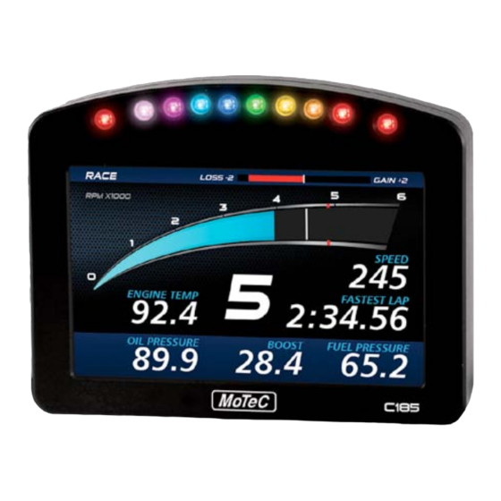
Configuration Display The C125 display is a high contrast, high brightness colour LCD display. The displayed channels and labels are configured on a display style chosen from predefined styles. To configure the display 1. On the Functions menu, click Display 2. - Page 34 MoTeC Configuration Display Modes (Pages) The display has three display modes; the default names are Race, Practice and Warmup. The mode is changed by pressing the button assigned to this function. The mode names can be changed to suit your individual needs; this is done by double-clicking on the Page Label field.
- Page 35 Configuration Dial or Bar Graph (depending on style chosen) Example dial Example sweep bar Example linear bar The dial or bar graph has a user definable range and is typically used as a tacho, however it can be used to display any other value. A fully programmable shift point can be displayed, which can also be gear dependent.
- Page 36 MoTeC Configuration Top Displays The three numeric displays shown above can be programmed to display any channel value. The numeric displays can show any channel value plus up to two override values. Override values display each time their value is updated. This is useful for values that are updated periodically.
- Page 37 Configuration Centre Display The centre display is normally used to display the current gear but can be used for other purposes. Bottom Display...
- Page 38 MoTeC Configuration At the bottom, up to 20 lines can be accommodated, with each line containing up to 3 channel values at a time. The label above each value can be changed to suit the channel assigned. The 20 lines can be scrolled up or down using external buttons. Similar to the top numeric displays, the bottom display can show up to four override values.
-
Page 39: Other Functions
• Shift Lights – to configure the shift point values for use with the Shift Lights. • Shift Light Module – to configure the C185 10 stage shift lights as well as an additional MoTeC's SLM-C or SLM. • Telemetry to set up telemetry channels •... - Page 40 MoTeC Configuration • Diagnostics Log Setup to set up conditions and channels for the diagnostics log • Preserved Channels to set up the conditions when to preserve channels Refer to C185 Dash Manager online help for additional information.
-
Page 41: Operation
From Dash Backups directory to use in case the data in the C185 needs to be restored. The maximum number of files is 10. • On the Online menu, click Get Configuration to retrieve the current... -
Page 42: Checking Operation
Test • On the Online menu click the appropriate test A number of tests are provided to check the operation of the C185, such as the Display Test. Configuration Versions and Updating • On the Online menu, click Upgrade Dash Version The software inside the C185 (firmware) can be updated by the user at any time to take advantage of the latest features. -
Page 43: Upgrading C185
Other Online Activities Many other activities are accessible from the Online menu including the following: • Set Reference Lap to send a reference lap to the C185 used in the lap gain/loss system. See Calculations. • View to view: o configuration settings e.g. Tell-tales, Engine Log o GPS Beacon Definitions o saved details e.g. - Page 44 Serial Number to view the Serial and Hardware Number. The Serial Number is required when ordering upgrade passwords. The Hardware Number is for MoTeC internal use. o Change Display Mode to switch between Race, Warm-up and Race mode Refer to C185 Dash Manager online help for additional information.
-
Page 45: Appendices
These additional features are activated through a simple password acquired from MoTeC, at any time when you need it. An overview of the upgrades can be found in C185 Upgrades. Logging • 250 MB standard logging memory (500 MB optional) •... - Page 46 MoTeC Appendices Internal Sensors • 3 axis G sensor • Dash temperature sensor • Sensor supply voltage • Battery voltage Communications • 4 configurable CAN buses, with individually programmable CAN bus speeds. One can be used as RS232 Receive. Only 2 of the CAN buses support VIM/SVIM Expanders o Maximum data range 1 Mbit/sec o Recommended terminating impedance 100 ohm...
-
Page 47: C185 Upgrades
These additional features are activated through a password acquired from MoTeC, at any time when you need it. For the C185 Dash Logger the following upgrades are available: Data Logging Increases the internal logging memory to 500 MB. (Standard 250 MB memory... -
Page 48: Characteristics
MoTeC Appendices Characteristics Input Characteristics Analogue Voltage Inputs Suitable for: Potentiometers Voltage output sensors Variable resistance sensors with pull-up resistor Measure Voltage Inputs 1—4 and 11—14: 0 to 5.46 V Range: All other Inputs: 0 to 15.0 V Note: Voltages outside this range may affect the readings on other inputs. - Page 49 Appendices Analogue Temp Inputs Suitable for: 2 wire variable resistance sensors some voltage output sensors Measure Voltage Range: 0 to 15.0 V Note: Voltages outside this range may affect the readings on other inputs. Input Resistance: 1000 ohms pull-up to 5 V sensor supply +100 k to 0 V Resolution: 3.66 mV...
- Page 50 MoTeC Appendices Digital Inputs Suitable for: Switch to 0 V Logic signal and open collector device (e.g. Hall Switch) Pull-up Resistor: 2200 ohms to 3.3 V Voltage Range: 0 to 15 V Positive Trigger Threshold: 2.4 V max Negative Threshold: 0.6 V min Hyst eresis: 0.4 V min...
- Page 51 Appendices Speed Inputs A 2200 ohm pull-up resistor connected to 2.7 V. Hall mode Suitable for: Switch to 0 V Logic signal Open collector device (e.g. Hall Switch) Pull-up Resistor 2200 ohms to 2.7 V Voltage Range 0 to 15V Trigger Threshold Selectable between -1.33 V and 4.68 V Magnetic mode...
- Page 52 MoTeC Appendices Period 100 usec Measures period between falling edges Resolution 100 usec Maximum 3.2 sec Pulse Width 1 usec Measures pulse high time Resolution 1 usec Maximum 32 msec Pulse Width 100 usec Measures pulse high time Resolution 100 usec Maximum 3.2 sec...
-
Page 53: Output Characteristics
Appendices Analogue Input Sampling 4 times oversampling is scheduled with samples taken every 250 usec, providing measurements every 1 msec. The following inputs are sampled at 250 usec, with microsecond offsets as shown in the table: 0.0 usec +1.5 usec +3.1 usec Offsets 0.0 usec... -
Page 54: Pin List By Pin Number
MoTeC Appendices Pin List by Pin Number Name Function AV15 Analogue Voltage Input 15 AV16 Analogue Voltage Input 16 AV17 Analogue Voltage Input 17 AV18 Analogue Voltage Input 18 AV19 Analogue Voltage Input 19 Sensor 0 V BAT- Battery Negative BAT+ Battery Positive AUX1... - Page 55 Appendices Name Function AV14 Analogue Voltage Input 14 Sensor 0 V Sensor 5 V Reserved Reserved Reserved Reserved Sensor 0 V Analogue Temp Input 1 Analogue Temp Input 2 Analogue Temp Input 3 Analogue Temp Input 4 Analogue Temp Input 5 Analogue Temp Input 6 Sensor 0 V Analogue Temp Input 7...
- Page 56 MoTeC Appendices Name Function DIG2 Digital Input 2 DIG3 Digital Input 3 DIG4 Digital Input 4 Sensor 0 V Switch Input 1 Switch Input 2 CAN4L CAN 4 Low CAN4H CAN 4 High Sensor 0 V Sensor 8 V SPD1 Speed Input 1 SPD2 Speed Input 2...
-
Page 57: Pin List By Function
Appendices Pin List by Function Name Function Battery Power BAT- Battery Negative BAT+ Battery Positive Analogue Voltage Inputs Analogue Voltage Input 1 Analogue Voltage Input 2 Analogue Voltage Input 3 Analogue Voltage Input 4 Analogue Voltage Input 5 Analogue Voltage Input 6 Analogue Voltage Input 7 Analogue Voltage Input 8 Analogue Voltage Input 9... - Page 58 MoTeC Appendices Name Function Analogue Temp Inputs Analogue Temp Input 1 Analogue Temp Input 2 Analogue Temp Input 3 Analogue Temp Input 4 Analogue Temp Input 5 Analogue Temp Input 6 Analogue Temp Input 7 Analogue Temp Input 8 Switch Inputs Switch Input 1 Switch Input 2 Digital Inputs...
- Page 59 Appendices Name Function AUX2 Auxiliary Output 2 AUX3 Auxiliary Output 3 AUX4 Auxiliary Output 4 AUX5 Auxiliary Output 5 AUX6 Auxiliary Output 6 8 V Sensor Sensor 8 V 5 V Sensor Sensor 5 V Sensor 5 V Sensor 5 V 0 V Sensor Sensor 0 V Sensor 0 V...
- Page 60 MoTeC Appendices Name Function CAN2H CAN 2 High / RS232 Receive Input CAN3L CAN 3 Low CAN3H CAN 3 High CAN4L CAN 4 Low CAN4H CAN 4 High Ethernet E-TX- Ethernet Transmit - Ethernet Transmit + E-TX+ E-RX- Ethernet Receive - Ethernet Receive + E-RX+ RS232...
-
Page 61: Mounting Dimensions
Appendices Mounting Dimensions C185 Note: • All dimensions in [mm] • Ensure product is not stressed when mounted • Dimensions indicate actual product size, allow for clearance when mounting... -
Page 62: Wiring
C185 connector #68086 Mating connector Wire Specification Wire Wire to suit C185 connector: 22# Tefzel, Mil Spec : M22759/16-22 M22759/16 Wire Ratings (for various wire gauges) Insulation Material: Tefzel Conductor: Tin Plated Copper Voltage Rating: 600 V Maximum Temperature: 150 °C... -
Page 63: Pc Connection
Wire CAT5 UTP Ethernet cable Cable An Ethernet RJ45 socket, connecting to a standard Ethernet cable, is provided on: • #62207 C185 loom incorporating • #61131 Ethernet cable, unterminated, 2 meter • #61132 Ethernet to Autosport pins cable, 1.8 m... -
Page 64: Can Bus Wiring Requirements
MoTeC Appendices CAN Bus Wiring Requirements • The CAN bus should consist of a twisted pair trunk with 100R (0.25 watt) terminating resistors at each end. o If the CAN bus is less than 2 meter (7 ft) long, a single termination resistor may be used. -
Page 65: C185 To Ecu Wiring (Rs232)
MoTeC ECUs via RS232. In all cases this is done using the serial data stream generated by the Telemetry function of each ECU. In the case of the M800, M880 and M4e the C185 may be directly wired to the ECU because these ECUs use RS232 interface levels. On the M48, M4 (pre M4e) and the M8, a Computer Interface Module (CIM) or a PCI cable is required to convert the signals to RS232. - Page 66 MoTeC Appendices Using a CIM Module Refer to the CIM module drawing for full wiring details. Note: The data to the C185 will be interrupted while a PC is connected.
-
Page 67: Update Rate Summary
Appendices Update Rate Summary Device Input Type Maximum Update Rate (per second) C185 Analogue Voltage Inputs 1000 C185 Analogue Temperature Inputs 1000 C185 Digital Inputs and Speed Inputs C185 RS232 and CAN Communications 50 max * C185 CAN comms fast receive... -
Page 68: Command Line
MoTeC Appendices Command line Usage: dash.exe -c[connection] -d -x -l -e -t -s [config file name] [config file name] (Optional) Fully qualified path to the configuration file. (eg "c:\motec\dash\config\bathurst.d30") Note: the path must included the file extension (eg .d30) Options : Each of the following options can be given as "/[character]"... - Page 69 Appendices Tasks : One or more of the following may be specified. (Optional) Perform a “Get Logged Data” operation. (Optional) Perform a “Get Engine Log” operation. (Optional) Perform a “Get Tell-tale Values” operation. (Optional) Perform a “Print Summary” operation. Note: The configuration file must be specified using a fully qualified path including the file extension.
-
Page 70: Can Bus Bandwidth Limit
If the total bandwidth required exceeds this specification then some devices should be connected to the second CAN bus. Note: C185 Dash Manager will warn if the bandwidth is likely to be exceeded. Approximate Bandwidth = Total Measurement Rate (samples/sec) x 30 (bits... -
Page 71: Comms Error Codes
NOISE Glitch in the data. Electrical interference is causing glitches in the signal. (C185 does not generate this error) OVERRUN A byte was received before the previous byte was read indicating that the processor was too busy to read the message. - Page 72 CAN TRANSMIT CAN bus transmit warning "VIMCOM" Errors Errors generated by "VIMCOM" devices (VIM, ADL2, SDL). Note: VIM COM devices are connected via CAN. C185 Errors These errors are generated by the C185 communications system. FRAMING Incorrect number of samples received.
- Page 73 BAD CONFIG Configuration mismatch between C185 and device. Resend the configuration. NO DATA VIMCOM packets have not been found. Either there is a wiring fault or C185 Connections is setup incorrectly. 2048 WRONG DATA VIMCOM packet has bad length. 4096...
-
Page 74: Pc Connection - Ip Address
PC Connection - IP Address Basic Direct Connection (Automatic IP Address) The simplest way to connect the C185 to a PC is directly to an Ethernet port on the PC and using the default network settings (automatically obtain an IP address) This method can take up to 60 seconds to connect on Windows XP. - Page 75 Appendices Fast Direct Connection (Fixed IP Address) If the Basic Direct Connection method takes too long to connect, a more advanced setup can be used to reduce connection times to around 3 seconds. Notes: • Please be aware that changing the PC's network settings can make connections to other devices on the network stop working.
- Page 76 The C185 can also be connected to a network rather than directly to a single PC. This allows any PC on the network to communicate with the C185. The connection time to the C185 will be less than 3 seconds (if the C185 is already powered and running)
- Page 77 Appendices Network Switches and Cables The C185 must be connected to the network via a network switch. All MoTeC's PC connection cables (see PC Connection) are Ethernet crossover cables, that allow direct connection to a PC and are compatible with network switches that support auto cable sensing (sometimes called “Auto-...
-
Page 78: Windows Keyboard Shortcuts
MoTeC Appendices Windows Keyboard Shortcuts When using a laptop in and around a car, it is often not practical to use a mouse to navigate through the program. Using the keyboard to select options is easier. Main Menu To access the main menu, press ALT + the key for the underlined letter in the menu, followed by the underlined letter of the item in the drop down menu. - Page 79 Appendices Selecting an Item in a Window To access the various items in a window, press ALT + the key for the underlined letter of the item of interest, e.g. to select the ‘Flash Light’ item press ALT + F Alternatively use the TAB key to move through the dialog box (use SHIFT + TAB to move backwards).
- Page 80 MoTeC Appendices Group Box The Group box is used to select an item from a group of options. Press ALT + the key for the underlined letter (F, A or D), or use the TAB key to navigate to the Group box. To select, use the arrow keys. Text Box A text box is used to enter a value or text.
- Page 81 Appendices Press ALT + the key for the underlined letter (L) or use the TAB key to navigate to the Drop down List Box. To select the desired item, use the arrow keys, and press ENTER to close the list. Tabs Tabs are used to select the different tab pages of a screen.
-
Page 82: Glossary
MoTeC Appendices Glossary MoTeC Devices Advanced Central Logger ADL2 Advanced Dash Logger - second generation C185 Colour Display Loger Beacon Receiver Beacon Transmitter Computer Interface Module Central Logging System DBW4 Drive By Wire expander E816 Input/Output Expander E888 Input/Output Expander... - Page 83 Appendices PDM16 Power Distribution Module with 16 outputs PDM30 Power Distribution Module with 30 outputs PDM32 Power Distribution Module with 32 outputs Professional Lambda Meter Real Time Clock Subaru Diff Controller Sport Dash Logger Strain Gauge Amplifier Shift Light Module Software Update Unit Traction Control Module Versatile Input Module...
- Page 84 MoTeC Notes...
Need help?
Do you have a question about the C185 and is the answer not in the manual?
Questions and answers