Table of Contents
Advertisement
Quick Links
Advertisement
Table of Contents

Summary of Contents for Kapat KARAT-520
- Page 1 OPERATIONS MANUAL KARAT-520 Ultrasonic flowmeters...
- Page 2 KARAT-520 Ultrasonic flowmeters...
-
Page 3: Introduction
Karat-520 ultrasonic flowmeters and (or) their component parts is prohibited. Karat-520 ultrasonic flowmeters are included in State Register of mea- suring instruments under register number № 44424-12 (Pattern Approval Certificate of Measuring Instruments RU.C.29.005.A № 47132). -
Page 4: Table Of Contents
Ultrasonic flowmeters КАRАТ-520 КАRАТ RPA www.karat-npo.ru TABLE OF CONTENTS INTRODUCTION ................2. INTENDED USE ................30 TABLE OF CONTENTS ..............2.1. Operating limitations ............. 30 LIST OF ABBREVIATIONS AND DESIGNATIONS ......2.2. Recommendations for choosing a flowmeter ......30 1. -
Page 5: List Of Abbreviations And Designations
СМАФ.407251.002 РЭ Edition 3.0 . August 2012 Ultrasonic flowmeters КАRАТ-520 LIST OF ABBREVIATIONS AND DESIGNATIONS ND — nominal diameter of pipeline or flowmeter; MS — measuring section of pipeline; — mounting insert in pipeline; VM — verification method; OM — operations manual; SW —... -
Page 6: Description And Operation
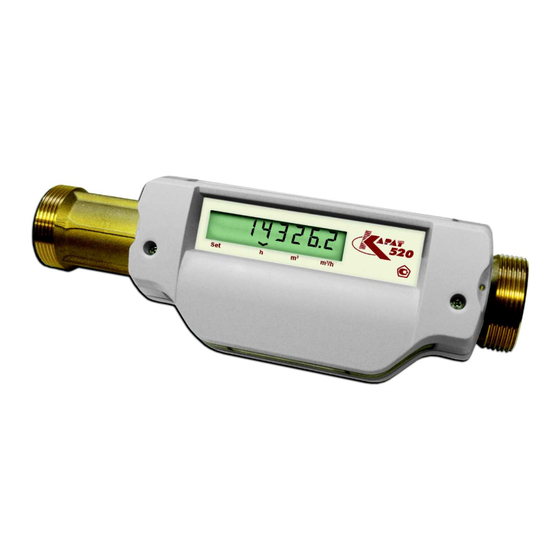
“Uraltechnology” RPE is the following: 1.1. Purpose and application KARAT-520 ultrasonic flowmeters are designed for industrial and commercial metering of volume flow and liquid volume in filled pipe- lines of heating systems, cold and hot water supply under conditions КАRАТ-520 - ХХ... - Page 7 Built-in battery 3.6 V means of flanges. External power supply (24 ± 12) V KARAT-520 appearance is presented on the figures 1.1 and 1.2. Digital interface RS-485 Digital interface M-Bus Current output 4-20 mA Pulsed output Figure 1.1 –...
-
Page 8: Performance Characteristics
Ultrasonic flowmeters КАRАТ-520 КАRАТ RPA www.karat-npo.ru 1.3. Performance characteristics Water or other nonaggressive fluid with the following characteristics is used as a working fluid in the flowmeters: 1.3.1. Specification and metrological performance working fluid density, kg/m ……....……………700–1200; Flowmeters have the specified technical and metrological character- –6 –6 kinematic viscosity of a working fluid, m /s..0,19•10 —... -
Page 9: Output Signals Parameters
.......2; for different dimension types are given on figure 1.3 maximum switching current in an output circuit, mA …....10. Flowmeter of KARAT-520-ХХ-3 design version has 2 analog elements КАRАТ-520-40 КАRАТ-520-40 with current signal parameters according to GOST 26.011(“Measuring and automation devices. -
Page 10: Electromagnetic Compatibility Requirements
Ultrasonic flowmeters КАRАТ-520 КАRАТ RPA www.karat-npo.ru 1.3.5. Electromagnetic compatibility requirements 1.3.6. Failure properties Flowmeters are resistant to the following types of electromagnetic in- Mean time between failures of the flowmeters accounts for terferences: 50000 hours.Mean lifetime of the flowmeters accounts for 12 years. electrostatic discharges in accordance with GOST R 51317.4.2 (“Elec- Storage time of service and archival data in nonvolatile memory of the tromagnetic compatibility of technical equipment. -
Page 11: Operation And Description Of A Flowmeter
FT are marked in accordance with 1.6.1 clause of the present OM. tube FT and electronic module EM, integrated in a single device, see figure 1.4. Thread mounted Flange mounted Figure 1.4 – KARAT-520 flowmeters — electronic module; — marking; — pulse output wire; — interface module wire;... - Page 12 (RS-485, M-Bus), or current output module. Built-in battery is connected to a socket (12 callout, figure 1.7). Interface mod- There is a flow conditioner (1 callout, figure 1.6) in KARAT-520-40, ules and current output module are also connected to a socket -50, -65, -80 flowmeters, which reshapes velocity profile after distur- (10 callout, figure 1.7).
- Page 13 — plastic tube; — flow conditioner; — PET transducer; — plastic tube; — reflectors — tube flaring in the low end of tube – KARAT-520-40* flowmeters are thread mounted (1.2 section of the manual) Description Intended use Maintenance Verification Repair...
- Page 14 Ultrasonic flowmeters КАRАТ-520 КАRАТ RPA www.karat-npo.ru Flowmeters have direct and reverse pulse outputs.Devices marked Galvanic separation (optocoupler) allows to separate external com- with “R” symbol have normalized metrological characteristic in case munication line from internal circuit of a flowmeter. of reverse flow. m /h Ultrasonic flowmeter 3 V 0,05 W...
- Page 15 СМАФ.407251.002 РЭ Edition 3.0 . August 2012 Ultrasonic flowmeters КАRАТ-520 Figure 1.7 (end) – Electronic module appearance (without top cover) m /h — holes for sealing; — liquid-crystal display; — bottom part of EM body; — top part of EM body; —...
-
Page 16: Flowmeter Operation
Ultrasonic flowmeters КАRАТ-520 КАRАТ RPA www.karat-npo.ru 1.4.2. Measuring principle The flow meter operates by alternately transmitting and receiving a burst of sound energy between two piezoelectric transducers and measuring the transit time that it takes for sound to travel between the two transducers. - Page 17 СМАФ.407251.002 РЭ Edition 3.0 . August 2012 Ultrasonic flowmeters КАRАТ-520 Warning! Parameters displayed on LCD are indicated accurate to 7 signifi- cant digits (characters). Eighth digit is used for indication of display modes. m /h Instantaneous flow rate Sequence of parameters change mentioned above is called standard display mode.
- Page 18 Ultrasonic flowmeters КАRАТ-520 КАRАТ RPA www.karat-npo.ru During extended display precision mode parameters are indicated on LCD every 3-4 seconds. Standard display mode is switched automati- cally after 5 cycles of measured parameters display, figure 1.10 Standard display mode Extended display precision mode m /h m /h m /h...
- Page 19 СМАФ.407251.002 РЭ Edition 3.0 . August 2012 Ultrasonic flowmeters КАRАТ-520 Instantaneous flow rate represents a current flow rate value of work- ing fluid. The present parameter is displayed on LCD with 5 significant digits. Examples of instantaneous flow rate are given on figure 1.11. Instantaneous flow rate is 0,0000 m /h...
- Page 20 Ultrasonic flowmeters КАRАТ-520 КАRАТ RPA www.karat-npo.ru Cumulative forward volume represents the value of working fluid point. If the value exceeds 1000 m cumulative volume value is volume, accumulated since device installation in case of forward flow. indicated accurate to 3 digits after decimal point. If the value exceeds The present parameter is indicated on LCD in both display modes.
- Page 21 СМАФ.407251.002 РЭ Edition 3.0 . August 2012 Ultrasonic flowmeters КАRАТ-520 Indicator is signaling about In extended display precision mode cumulative volume is always the absence of high order digits display indicated on LCD accurate to 4 digits after decimal point. In this case high order digits (starting from 1000 m ) are not displayed on LCD.
- Page 22 Ultrasonic flowmeters КАRАТ-520 КАRАТ RPA www.karat-npo.ru Standard display mode Cumulative reverse volume represents the value of working fluid vo- lume, accumulated since device installation in case of reverse flow. Indicator is signaling about reverse flow measurement This parameter is indicated on LCD only in case of nonzero value. Cumulative reverse volume values are viewed similarly to cumulative forward volume values.
- Page 23 СМАФ.407251.002 РЭ Edition 3.0 . August 2012 Ultrasonic flowmeters КАRАТ-520 m /h m /h Checksum of calibration constants m /h m /h Pulse weight (0.0001 m /pulse) Factory number – seс m /h m /h Version of embedded software Checksum of embedded software Figure 1.16 –...
- Page 24 Ultrasonic flowmeters КАRАТ-520 КАRАТ RPA www.karat-npo.ru KARAT-520-ХХ-0 flowmeters are connected to the calculator (re- cording unit) by means of pulse outputs. Connection diagram of KARAT-520-ХХ-0, -R is presented on 1.17 figure. КАRАТ-520-ХХ-0 КАRАТ-520-ХХ-0-R Pulse output Pulse output OUT1 OUT1 Black...
- Page 25 Input OUT 1 OUT 1 Black Black Blue Blue OUT 2 OUT 2 White White Figure 1.18 – Diagram of KARAT-520-ХХ-0, KARAT-520-ХХ-0-R connection to KARAT-307 and ELF calculators Description Intended use Maintenance Verification Repair Transportation Utilization and operation and warehousing...
- Page 26 КАRАТ RPA www.karat-npo.ru Loggers are located in interface modules: External power source with voltage 12-36 V and interface converter RS-232/RS-485 or USB/RS-485 are required in case of KARAT-520- RS-485 (KARAT-520-ХХ-1-А design version); ХХ-1-А connection to RS-485 interface. M-Bus (KARAT--520-ХХ-2-А design version).
- Page 27 . interface. KARAT-520-ХХ-3, -R connection diagram is given on figure 1.20. Data transfer rate by M-Bus interface is set during flowmeter configu- ration and it can be within the range of 600 bit/sec up to 4800 bit/sec.
-
Page 28: Marking And Sealing
Flowmeters structure provides for 2 sealing levels. 1 level — QCD (quality control department) seal (6 callout, figure 1.7) Table 1.5 – Marking labels for KARAT-520 flowmeters placed after manufacturing and seal stamped with verification mark Marking label Marking place (7 callout, figure 1.7). -
Page 29: Warranty
4 years from the date of device sale by the manufacturer. Manufacturer Scope of flowmeter delivery comprises: warranties are described in details in flowmeter certificate. KARAT-520 ultrasonic flowmeter; operations manual; certificate; verification method VM 22-221-2012 (it is acceptable to supply 1 co- py of verification method to 1delivery address). -
Page 30: Intended Use
Ultrasonic flowmeters КАRАТ-520 КАRАТ RPA www.karat-npo.ru 2. INTENDED USE 2.2. Recommendations for choosing a flowmeter Choosing the optimal dimension type of a flowmeter is the main con- dition of its reliable operation, durability and acquisition of consistent 2.1. Operating limitations measurement results. -
Page 31: Preparation For Use
СМАФ.407251.002 РЭ Edition 3.0 . August 2012 Ultrasonic flowmeters КАRАТ-520 2.3. Preparation for use Straight sections should be chosen in accordance with the rules, given in 2.1 table. 2.3.1. General requirements In case of the presence of several hydraulic resistances just up- People with electrical safety level better than II who studied the fol- stream the flowmeter, requirements of 2.1 table should be met for lowing manual and passed safety training are admitted to operation... -
Page 32: Preparation For Installation
Ultrasonic flowmeters КАRАТ-520 КАRАТ RPA www.karat-npo.ru In case of flowmeter installation with additional “R“ function on re- Reducers are mounted on the pipeline beyond straight pipes area. verse flows inlet and outlet pipes lengths should be the same and In order to eliminate measured fluid leakage at the working pressure equal to inlet pipe length for the case of forward flow. - Page 33 Outlet pressure of the working fluid should be not less than during flowmeter operation. 0.05 MPa (0.5 kg/cm ) for KARAT-520-20, -25, -32 and not less than 0.1 MPa (1,0 kg/cm ) for KARAT-520-40, -50, -65, -80. In certain cases (when other mounting variants are not possible) it is allowed to install the flowmeter on downstream pipelines, subject to conditions, mentioned above.
- Page 34 Ultrasonic flowmeters КАRАТ-520 КАRАТ RPA www.karat-npo.ru It is allowed to mount flowmeter without straight pipes insert in case of fulfilment of the following conditions: the values of straight pipes lengths should meet the requirements of 2.1 table; internal diameter of pipeline adjacent to flowmeter may differ from the specified dimension type of a flowmeter not more than by 10 %, in this case internal diameter of a pipeline should always be greater than flowmeter FT.
-
Page 35: Installation Work
(Lmount) depends on nominal diameter, its val- ues are given in table 2.3. MI for КА АТ-520-20, -25, -32, -40 Table 2.3 – Setting dimensions of KARAT-520 flowmeters КАRАТ-520 mount , mm It is allowed to mount flowmeter without straight pipes insert in case of Figure 2.5 –... - Page 36 (“Hexagon bolts, product grade B. Construction and dimensions”), screws in accordance with GOST 9515 (“Piston metal rings for piston compressors. Specifications”)). SAE 2 is used both for KARAT-520-50, -65, -80 flowmeters mounting GOST 16037-80-У7 on the pipeline with no cutting-in of straight pipes and for independent...
- Page 37 СМАФ.407251.002 РЭ Edition 3.0 . August 2012 Ultrasonic flowmeters КАRАТ-520 Flanges welding to system pipeline in accordance with require- 2.3.4.4. Straight pipes mounting ments to flange installation accuracy, given on figure 2.6; Straight pipes should be mounted on pipeline as follows: Flowmeter installation after welding and mounting works completion.
-
Page 38: Electric Installation Work
Ultrasonic flowmeters КАRАТ-520 КАRАТ RPA www.karat-npo.ru 2.3.4.5. Flowmeter mounting calculator КАRАТ-520 It is recommended to obey the following rules during flowmeter instal- lation : Flowmeter should be installed on the pipeline between SAE ele- ments (straight pipes and welded flanges) in such a way that arrow direction on FT body corresponds to flow direction of working fluid in the pipeline;... -
Page 39: Flowmeters Use
СМАФ.407251.002 РЭ Edition 3.0 . August 2012 Ultrasonic flowmeters КАRАТ-520 2.4. Flowmeters use 2.4.1. Commissioning During flowmeter commissioning it is necessary to verify: Correctness of flowmeter installation; Specified pulse weight of flowmeter output signal; Correctness of flowmeter connections to external devices. In order to avoid water hammer effect, flow tube and measuring sec- tion of a pipeline should be gradually filled with water. - Page 40 Ultrasonic flowmeters КАRАТ-520 КАRАТ RPA www.karat-npo.ru СМАФ.407251.002 РЭ – Operations manual Edition 3.0. August 2012...
-
Page 41: Maintenance
СМАФ.407251.002 РЭ Edition 3.0 . August 2012 Ultrasonic flowmeters КАRАТ-520 3. MAINTENANCE In order to provide proper technical characteristics flowmeter mainte- nance is performed, which comprises the following: visual periodical inspection during operation; periodical verification; putting in prolonged storage in case of decommissioning. During visual inspection the following is verified: The absence of visual mechanical damages such as spalls, scratches and also corrosion marks of component parts materials;... - Page 42 Ultrasonic flowmeters КАRАТ-520 КАRАТ RPA www.karat-npo.ru СМАФ.407251.002 РЭ – Operations manual Edition 3.0. August 2012...
-
Page 43: Verification
Being measuring instruments flowmeters are subject to initial and pe- riodic verification. Flowmeters verification is performed in accordance with VM 22-221- 2012 “SSM (State System for Ensuring Uniform Measurement). KARAT-520 ultrasonic flowmeters. Verification method”. Calibration period is 4 years. Description Intended use... - Page 44 Ultrasonic flowmeters КАRАТ-520 КАRАТ RPA www.karat-npo.ru СМАФ.407251.002 РЭ – Operations manual Edition 3.0. August 2012...
-
Page 45: Repair
The following documents should be delivered with flowmeter in case of repair: Reclamation report with failures description. Example of reclama- tion report is given in Appendix B of flowmeter certificate; KARAT-520 Certificate SMAF.407251.002 PS. Description Intended use Maintenance Verification... - Page 46 Ultrasonic flowmeters КАRАТ-520 КАRАТ RPA www.karat-npo.ru СМАФ.407251.002 РЭ – Operations manual Edition 3.0. August 2012...
-
Page 47: Transportation And Warehousing
СМАФ.407251.002 РЭ Edition 3.0 . August 2012 Ultrasonic flowmeters КАRАТ-520 6. TRANSPORTATION AND WAREHOUSING Flowmeters are shipped in manufacturer packing by all types of cov- ered transport means, including air transport, in heated sealed com- partments in accordance with GOST R 52931 (“Instruments for pro- cess monitoring and control. - Page 48 Ultrasonic flowmeters КАRАТ-520 КАRАТ RPA www.karat-npo.ru СМАФ.407251.002 РЭ – Operations manual Edition 3.0. August 2012...
-
Page 49: Utilization
СМАФ.407251.002 РЭ Edition 3.0 . August 2012 Ultrasonic flowmeters КАRАТ-520 7. UTILIZATION Flowmeters contain no precious metals and materials which require special utilization methods and pose direct threat to life and health of people. Operating organization implements measures for overaged flow- meters utilization. -
Page 50: Appendix A - Diagram Of Flowmeters Installation
APPENDIX A – Diagram of flowmeters installation APPENDIX B – Pattern Approval Certificate of MI of KARAT ultra- sonic flowmeters in Russian Federation Figure A.1 – Installation diagram of KARAT-520-20, -25, -32, -40 flowmeters Figure A.2 – Installation diagram of KARAT-520-50, -65, -80 flowmeters СМАФ.407251.002 РЭ... - Page 52 www.karat-npo.ru DELIVERY IN ANY REGION OF RUSSIA OPERABILITY STOCK RESERVE HEAD OFFICE: Yasnaya st. 22-B, Yekaterinburg, 620102 Russia Tel./fax: +7 343 22 22 306, +7 343 22 22 307 e-mail: ekb@karat-npo.ru TECHNICAL SUPPORT: Yasnaya st. 22-B, Yekaterinburg, 620102 Russia Tel./fax: (343) 375-89-88; icq: 600 995 810 e-mail: tech@karat-npo.ru...
Need help?
Do you have a question about the KARAT-520 and is the answer not in the manual?
Questions and answers