Advertisement
Quick Links
DTHC-SETUP/INSTALL
For use with the following CandCNC products:
UBOBII Builders Kit + DTHC
UBOB III Builders Kit + DTHC
MP3000-DTHC rev B or later
BladeRunner (all versions) with DTHC option
BladeRunner AIO Dragon-Cut
DCP Digital Current Probe
DCP-01 with REV15 THC Sensor (2/23/2011)
Smart-Kut Software Upgrade (10/15/2010)
Use this manual to install and setup a DTHC Expansion
Module in the field for any of the above listed CandCNC
products OR to setup and test the DTHC functions in a
a CandCNC Product that already has the DTHC Module
Includes complete setup and testing of the new CandNC
CandCNC
MANUAL
(11/02/2010)
installed.
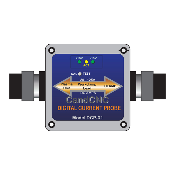
DIGITAL CURRENT PROBE
+15V
-15V
ACT
CAL
TEST
20 - 125A
Plasma
Workclamp
CLAMP
Unit
Lead
DC AMPS
CandCNC
CandCNC
DIGITAL CURRENT PROBE
Model DCP-01
REV6
FEB 2011
JAN 25th 2011
Advertisement

Related Manuals for CandCNC DCP-01

Summary of Contents for CandCNC DCP-01
- Page 1 Smart-Kut Software Upgrade (10/15/2010) Use this manual to install and setup a DTHC Expansion Module in the field for any of the above listed CandCNC products OR to setup and test the DTHC functions in a a CandCNC Product that already has the DTHC Module installed.
- Page 2 Files section. Some complete products from CandCNC may not have the correct version of the UBOB to do a direct plug of the DTHC and there may not be a slot for the card in the front panel. Please advise us if you need a new front panel with a slot for the DTHC and which product you have.
- Page 3 The photo shows a top view of the DTHC module card. There are two connections to make. The first is the 16 pin IDC cable between the DTHC and the UBOB Feature Connector. It’s the only 16 pin header on the UBOB. Both headers are keyed so the cable only fits one way.
- Page 4 Open MACH using the MP3000-DTHC-UBOBiii or BladeRunner AIO profile (for the product you have) and select CONFIG PLUGINS from the CONFIG menu in the top row. You will see a list of plugins that are available At the top of the list are the two CandCNC plug-ins. Each one starts with “ccc_”...
- Page 5 ? Use the screen to select the hardware you are using. The Ubob THC Plugin should be selected. If you have a ESPC Power supply (part of all RouterPak and PlazPak products) then be sure to check that as well. Note the COM port selection box. In most circumstances that will stay on “1”.
- Page 6 NO POLARITY CAUTION! NO POLARITY CAUTION! HIGH VOLTAGE HIGH VOLTAGE FOR CT (Current Transformer) Input Only. See page information CandCNC ARC OK LED ACTIVE ONLY WHEN CT INPUT is USED. NOTE: BOARD Lettering (silkscreen) on REV14 ARC OK cards is REVERSED Input Jack For J11 and J10.
- Page 7 J19 Located inside Cabinet on PC Board (ELECTRODE WIRES) Spark Gap For HV Systems CAUTION! HIGH VOLTAGE START SIGNAL CAUTION! CAUTION! HIGH VOLTAGE HIGH VOLTAGE CandCNC ARC XFR ARC OK LED ACTIVE ONLY WHEN CT INPUT is USED. ARC OK Connector for TORCH OPTIONAL DCP ACTIVE...
- Page 8 The ARC OK is used only when the control has the THC enabled (Screen button). IT IS REQUIRED for Automated cutting with THC. All CandCNC THC Sensor cards have had the ability to use an external Current Transformer (CT) placed in the AC line to the plasma.
-
Page 9: Special Note
DCP Setup section to For detailed instructions on how to install, setup and calibrate the help identify if your DTHC can accept the new DCP. DCP with any DTHC based CandCNC product see the DCP Setup section at page_________ PAGE 9... - Page 10 CONNECTIONS FOR SYSTEMS USING DIGITAL CURRENT PROBE THC SENSOR REV15 card WITH RJ11 connector on DCP-01 PLASMA WORKCLAMP LEAD (wire) TO TORCH POS (WORKCLAMP WIRE) CAUTION! HIGH VOLTAGE CAUTION! HIGH VOLTAGE CAUTION! HIGH VOLTAGE CandCNC Hookups for DCP-01 To RJ11 Jack...
- Page 11 START SIGNAL Spark Gap For HV Systems CAUTION! HIGH VOLTAGE CAUTION! CAUTION! HIGH VOLTAGE HIGH VOLTAGE J12 connector CandCNC located on rear ARC OK LED ACTIVE ONLY WHEN CT INPUT of unit. is USED. ARC OK Connector for TORCH OPTIONAL DCP...
- Page 12 CONNECTING HAND TORCH TO THC SENSOR CARD Use ScotchLoc IDC Splices (RED) to tie Torch Switch output on THC Sensor (J10) Screw Terminals. Locate Orange and Violet wires at J10 in the PowerMAX box and tap each wire as shown. To test short two screw terminals on J10 THC Sensor and torch should fire (Plasma Unit on) Connect to Screw...
- Page 13 HYPERTHERM PowerMAX 45 Connecting THC SENSOR CARD FOR OPERATION WITH MP3000-DTHC and BladeRunner Dragon-Cut series POWERMAX SIGNAL NAME(s) SENSOR NOTES WIRE Type REV14 REF TORCH SWITCH; PINS 3 & 4 J10 Screw For use with mechanical 18-22Ga stranded low START - MECH Term 1 &...
- Page 14 THI S SECTI O NRESERVEDFORPOWERMAX65. 8 5HOOKUPDATA PAGE 13...
- Page 15 MACH setup and you still cannot get the THC SENSOR to work contact us at 903-364-2740 or via e-mail at Tom @CandCNC.com NOTE: Some Larger (>100A) plasma units or older smaller models use various methods to start the initial ARC.
- Page 16 Hooking Up Your Plasma Machine to the MP3000- DTHC/BladeRunnerAIO DTHC CAUTION: Portions of this install may include opening your plasma cutter machine and attaching wires. MAKE SURE THE UNIT IS UNPLUGGED PRIOR TO REMOVING ANY COVER(S) OR MAKING ANY CONNECTIONS .
- Page 17 1. Most plasma units have connection terminals where wires from the torch or panel connectors attach to the internal PC Boards. The terminals provide a convenient place to do your connections. Use crimp-on spade or round terminals to attach the wires to the terminal strips. Make sure the new wires you install do not touch adjacent metal objects.
- Page 18 ARC OK trip point is set in the CUT PROFILES in MACH3. See the section on installing and calibrating the DCP-01/02 on how to set the ARC OK trip point. 6. If you have a plasma unit that DOES have an Arc Good signal or you have the DCP module , you do not need to install the Current Transformer and power resistor.
- Page 19 INSTALLATION OF CURRENT TRANSFORMER Used for plasma units that do not have Arc Good (Arc Xfer) signal or DCP Provided Power Resistor across terminals Wires to ARC OKAY 35 to 100A range Plasma units screw terminals on THC Sensor Card Pass one conductor from the AC line straight through the center of the Current Transformer Provided Power Resistor...
- Page 20 Digital Current Probe Model DCP-01 Physical install and hookup DCP-01 Digital Current Probel uses the existing THC SENSOR (rev14 or above) and slips over the Plasma System Workclamp lead wire to provide DC amp feedback to the DTHC and to the MACH screen.
- Page 21 It is important that each end is sealed to keep out plasma dust and smoke. Position the DCP-01 along the cable close to the plasma unit and in a place it will not get stepped on, crushed or can will dragged across the floor if you decide ot move your plasma unit or use it manually in the shop.
- Page 22 SETUP, TESTING and CALIBRATION of the DCP-01 DIGITAL CURRENT PROBE Do the following steps in order: 1. Connect the DCP-01 interface cable to the THC SENSOR using the wire colors and screw terminals on the THC SENSOR as shown. Most THC SENSOR cards were shipped without the plug screw terminals on the 5 exposed posts.
- Page 23 MACH or G-code. Secure DB9 on cards to Matching DB9 plugs on DTHC and THC Sensor 8. Run the calibration on the DCP-01 as per the manual even if you did it before and got the correct readings.\\ Addendum added 2/22/11...
- Page 24 2. Start MACH3 on the controller PC and load the profile and screen set for the DTHC. If this is the first time you have used the DTHC and MACH you should have had MACH loaded and setup. If you do not, STOP! Go back to the MP3000-DTHC or the BladeRunner AIO manual and first setup MACH and get your table moving and the proper MACH profile loaded for your system.
- Page 25 TORCH APMS readout is NOT 100 as shown. 1. To calibrate the DTHC module to the DCP-01 you must have access to the top of the DTHC Expansion Module. Refer to your product manual to identify and access the DTHC module.
- Page 26 DTHC EXPANION MODULE. Located above the UBOB III card in most CandCNC products.. Ribbon cable connecting DTHC down to UBOB card may cover adjustment Green Power LED pots. If so, gently move it out out the way. Shold be ON Do not unplug the ribbon cable or the card will be disabled.
- Page 27 OPERATION of the DTHC with the DCP-01. The primary purpose of the DCP-01 it give the operator real time feedback of the actual Cut Current. Using the settings in the Cut Profile you can set fault points (based on a percentage of the varience from the current preset value to warn the operator if cut current is too high or too low.
- Page 28 Grounding practices to reduce noise and increase safety MP3000-DTHC Interface/Control Box PC w/MACH3 Note THC Sensor Card shielded cable is not connected to any ground in the Control box Ground PC or Controllers to Earth Ground Rod. Conrollers will reference themselves to power ground through their AC lines Controller Cabinet MP3000 and UBOB have built in isolation on all inputs from the table...
- Page 29 That concludes the internal connections you will have to make for your unit. Make sure all leads are insulated and away from possible physical damage. Double check to make sure there are no loose connections and that you have attached/ re-attached any wires mentioned in the above guidelines. Replace all covers and safety devices on the plasma unit and plug the plasma unit into power with the unit switched off.
- Page 30 SETTING UP YOUR Z AXIS FOR AUTOMATIC TOUCH-OFF µ Make sure your Z is calibrated. When you move it 1” by the DRO it actually moves exactly 1”. If it does not find the axis setup section in the manual for your control and run the axis setup and calibration.
- Page 31 Establishing a material Zero with a floating head and sensor switch SEE PREVIOUS PAGE: Note to SHEETCAM (and SheetCAM TNG) users. We have provided special Posts for MACH3 and the MP3000-THC to be used when generating output from SheetCAM. It has an automatic “touch-n-go” feature that reads the traveled distance and once it exceeds 500mm (about 20 inches) a Z reference is performed just prior to the next pierce...
- Page 32 PAGE 30...
- Page 33 NOTE: If you are using when firing the torch against the metal. (doing a normal pierce). If it does the CandCNC Digital not light it is possible your torch is a smaller unit and you need to change Current Probe (DCP) it...
- Page 34 The following pages cover the operation and MP3000-DTHC Screen Section screens involved with the CUT PROFILES and the DTHC section of the screen. NOTE: The DTHC is used in all of our Plug-n-Run products including the MP3000, BladeRunner Dragon-Cut, and the UBOB Builders Kit + DTHC.
- Page 35 TORCH HEIGHT CONTROL section (continued) Tip Saver ON/OFF [new]. The Tip Saver ON/OFF button and Indicator LED allows the TIP Saver feature to be disabled. It’s used during setup to get the calibration (Preset Volts) within range and to test to observe the actual cut gap.
- Page 36 ALTERNATE SCREEN SET FOR SMART-KUT Using Smart-Kut for Plasma. Smart-Kut is an exclusive feature of the DTHC from CandCNC. It allows the operator to let the DTHC set it’s own PRESET VOLTS value rather than taking it from a Cut Profile or from the screen settings.
- Page 37 MP 3000 CONTROL SECTION The MP3000 Control provides controls to change the cut parameters for the DTHC. It allows the operator to set and change values before and while cutting. UP ARROW Button: The UP arrow increases the PRESET VOLTS by one full volt per click in essence raising the torch and increasing the gap.
- Page 38 To Adjust PRESET Volts (and Actual TORCH height) in one volt increments click VOLTS at the TIP the UP or DOWN Buttons Target volts you want Actual TORCH AMPS at the TIP MP3000 Conrol Secion (Cont) PRESET VOLTS . This is probabaly the most important DRO on the screen.
- Page 39 USING TORCH AMPS FOR TROUBLESHOOTING A BAD CUT. The TORCH AMPS can be a valuable tool to help diagnose and fix poor cutting or loss of arc and other annoying problems. Not all cut issues are from improper current but a good plasma cut cannot occur if the cut current is too far out of the specified value.
- Page 40 CURRENT SETTINGS BUTTON: Shows the current profile and settings being used by the DTHC. The DTHC uses a real time processor to process the torch volts and send the proper signals to MACH. The processor stores the settings in NVRAM (non-volatile ram) Changing any setting in the Settings Group or the General THC Settings and using (closes the window) saves the profile (writes it to the DTHC processor RAM.
- Page 41 Adding Profiles . As you do cutting on your table using the DTHC Digital Torch Height Control you will be able to choose optimized settings for each type of cutting you do. You can edit and save an existing Cut Profile or ADD a new one of you own. Since there are variables that change from one machine to another the sample values may or may not be usable in your environment.
-
Page 42: Profile Name
INFORMATION GROUP: The Information section at the top of the window is for storing information that you can refer to. It saves time by having the vital cut parameters instantly available to the operator The information group does not set anything for cutting and will not modify any cut parameters from the g-code. - Page 43 DTHC SETTINGS GROUP in Cut PROFILES SETTINGS GROUP: The Settings Group consists of important values that the DTHC uses to cut with. These values are not taken from code and need to be correct for the type of cutting you are doing. Changing a value in this group will change the way the DTHC reacts and cuts.
- Page 44 TIP SAVER % : This value determines the lowest the DTHC will let the torch head go down before it locks movement. It’s a percentage of the Preset Tip Volts. It constantly measures the actual tip volts and i the value is too high it keeps the Torch from moving down any lower. (remember that if the actual voltage is ABOVE the Preset it will LOWER the torch until they match.) Under certain cutting conditions, for example where the cut passes over a void or another cut line, the voltage will go up, and the normal reaction is for the torch to “dive”...
- Page 45 Cut Current This is the target cut current setting in amps based on the specific nozzle (tip) you are using and the material you are cutting. The suggested Cut Current is listed on the manufactures CUT CHART. If you do not have a cut chart for your plasma, set the value to the current rating of the nozzle (tip) you are using.
- Page 46 GENERAL THC SETTINGS The General THC Settings allow the operator to define cetain actions and options that are applied when a Fault or MACH conditon occurs. The General THC Options are GLOBAL. They apply to all Cut Profiles . Changing a setting changes it for all Cut Profiles.
- Page 47 THC Status box Gives visual feedback of THC ONLINE and the INCREMENTAL MOVES of the Z as it’s under DTHC Control. THC Moves DRO shows the actual realtime moves in incremental values of the Z. It does not show the absolute value of Z and changes to fast to be used as a position indicator but it allows the operator to confirm that moves are being sent to the pulsing engine in MACH to adjust the Z up and down.
-
Page 48: Final Testing
FINAL TESTING Doing a startup test using a manual cut ..DO NOT SKIP THIS TEST! 1. To establish that the DTHC is working and to find the best Tip Volts setting and initial cut height parameters, you should make a cut with the THC Button in MACH turned off , with the tip at the right cut gap for your plasma and watch the TORCH VOLTS... - Page 49 4. One of the most frequent mistakes made is either having the current setting on the plasma unit wrong for the nozzle you are using OR forgetting to clip on the workclamp. The DCP-01 will detect those type of conditions and warn the operator.
- Page 50 Kerf width: Sets the width offset used for inside or outside cuts. If you don’t know the value go back to you manual cut you made and measure the width. Feed Rate: The recommended feedrate for this tip. This is a default value and can be changed when you build the cut file to match the material you are cutting.
- Page 51 Troubleshooting DTHC Problems. 1. DTHC does strange things after a DTHC settings are wrong (wrong PRESET pierce (TIP SAVER locks on or tip VOLTS). plunges to the metal.) Pierce delay too long THC Delay in CUT PROFILE too SHORT. 2. UP and DOWN (LED’s) not coming Arc OK not working.
- Page 52 DO NOT attempt to run plasma without the proper MACH Profile (XML) loaded. Must be a CandCNC profile or a copy from our profiles. DO NOT call for support with vague descriptions or having not tested to a point DO NOT makes changes in the MACH config to the base profile.
- Page 53 Some torches will have more than one set of small wires for other sensors in the head. Confirm switch pair with an ohmmeter while operating the switch (Plasma Unit power OFF) Air and/or tip voltage Hi Volts Workpiece Clamp Torch Switch Wires Good connection to the workpiece with clamp is essential for proper operation of the THC HOW DTHC (THC/AVC/DTHC) WORKS...
-
Page 54: Raw Arc Voltage
RAW ARC VOLTAGE PLASMA UNIT TORCH SWITCH DCP Interconnect cable DB9 to DTHC Senosr Input connector Workpiece Clamp Good connection to the workpiece with clamp is essential for proper operation of the THC PAGE 52...
Need help?
Do you have a question about the DCP-01 and is the answer not in the manual?
Questions and answers