Table of Contents
Advertisement
Advertisement
Table of Contents

Summary of Contents for Ag Leader PF3000
- Page 3 Precision Farming System PF3000 Operators Manual...
- Page 5 Internet http://www.agleader.com Limited Warranty Ag Leader Technology will repair or replace at no charge any component of the PF3000 system that fails during normal service on the equipment model that the system was intended for use within two years from the date of first use.
- Page 6 PF3000 system. If you have a problem with your system, call your Ag Leader Technology Service dealer or call us directly at the phone number below. If we determine you have a hardware failure, we will ship replacement hardware immediately.
- Page 7 All the information recorded by the PF3000 must be recorded in a field and Fields and Loads load. The operator must manually select or change the field and load on the PF3000 during field operation.
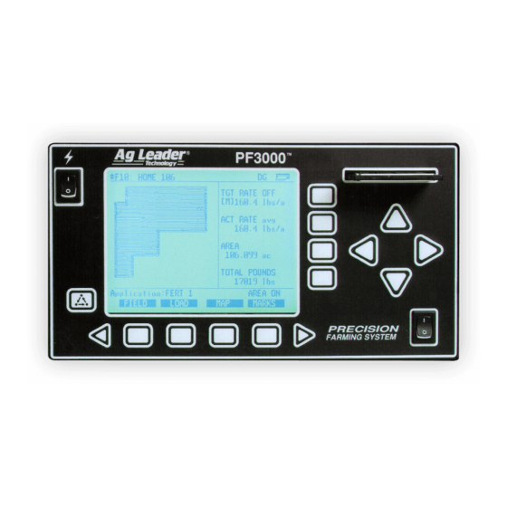
- Page 8 Switch Menu Selection Keys Figure 1: Front panel of the PF3000 Arrow Keys The UP, DOWN, LEFT and RIGHT ARROW keys on the right side of the keypad are used to select and change a setting. The bottom LEFT and RIGHT ARROW keys are only used to view more menu or display items.
- Page 9 General PF3000 Ag Leader Technology The PF3000 has four display lines for viewing items on the main operating Display and screen. You can choose which items you see on the display and the position Display Selection that the items appear on the display.
- Page 10 General PF3000 Ag Leader Technology symbol will appear on the right of the display line. This indicates you can change the setting of the item with the UP or DOWN ARROW keys. After you have made the change you must press the key to the right of the display line to deselect the line.
- Page 11 ON” or “AREA OFF” on the bottom right corner of the display to indicate the status of area couting. The PF3000 has four connectors on the bottom side of the console. The Connectors large 25-pin connector is for power and sensor connections. The three 9-pin ports (Port 1, Port 2, Port 3) are for connecting to a GPS receiver, planter or fertilizer or sprayer controller or any other GPS compatible device.
- Page 12 General PF3000 Ag Leader Technology Below is an example of a grain flow sensor. Your grain flow sensor may Grain Flow Sensor look different, depending on which combine model you have. On all combines, the grain flow sensor installs on top of the clean grain elevator.
- Page 13 General PF3000 Ag Leader Technology Below is an example of the moisture sensor mounted on the side of a clean Moisture Sensor grain elevator. The moisture sensor is installed in the elevator mount kit. Moisture Sensor Elevator Mount Kit Figure 5: Moisture sensor...
- Page 14 General PF3000 Ag Leader Technology Below is an example of a header height sensor installed underneath a Header Height combine cab. The header height sensor tells the monitor the position of the Sensor combine head so that when the head is raised on the end rows, the monitor stops counting area.
- Page 16 2-90 Flowmeter Controller Application Rate 2-95 The PF3000 console does not need to be in the vehicle to set it up. You can Using Power use the provided power supply (plugs into 120v outlet) to power up the Supply April 2002...
- Page 17 Setup Overview PF3000 Ag Leader Technology console inside your home or shop. April 2002...
- Page 19 Setup Overview PF3000 Ag Leader Technology All Modes Order of Keys Press the MENU key until you see the following keys on (Harvest Mode) the display. SUMMARY SETUP DIAG Press the SETUP key to view the following setup menu items.
- Page 20 Setup Overview PF3000 All Modes Ag Leader Technology Order of Keys Press MENU key Until you see the following keys on the the display. (Site Verification Mode) SETUP DIAG Press the SETUP key to view the following setup menu items.
- Page 21 Setup Overview PF3000 Ag Leader Technology All Modes Order of Keys Press the MENU key until you see on the following keys on (Application Rate the display. Mode) SETUP DIAG Press the SETUP key to view the following setup menu items.
- Page 22 Console Setup PF3000 All Modes Ag Leader Technology The console settings are general settings that apply to all operating modes Introduction and uses of the PF3000. To view the console setup screen press the: Console Setup Screen MENU key SETUP key...
- Page 23 Brightness brightness and press the ACCEPT key. Operating mode The PF3000 has the following operating modes: Grain Harvest, Grass Seed Harvest, Cotton Harvest, HarvestMaster™, Application Rate and Site Verification. Upon changing the operating mode you should make sure all setup items for that operating mode are correct.
- Page 24 Card Setup PF3000 All Modes Ag Leader Technology If you are using the GPS receiver, all the GPS data must be logged to a Introduction memory card. If you are not using a GPS receiver, you do not need a card.
- Page 25 Once you have changed a setting press the ACCEPT key. Press the EXIT key once you have made all the settings. Logging Device If you are using the GPS receiver with the PF3000 you must use a memory card to save the instantaneous GPS data. If you...
- Page 26 Log File The PF3000 requires a log file to store data on a memory card. The log file will always have a “.yld” extension and be named with the date the file was created.
- Page 27 Card Setup PF3000 Ag Leader Technology All Modes To copy memory to log files that are not set as the current log file, press the Copying Data to SHOW FILES key and select one of the log files. Press the FILE OPTIONS Log File key and press the COPY TO FILE key.
- Page 28 You should at least create all the fields and name them before you begin to use the PF3000. The monitor will use the same set of fields you create for each operating mode (harvest mode, application rate mode, site verification) of the monitor.
- Page 29 Creating, Naming Fields, Loads PF3000 Ag Leader Technology All Modes except App Rate Creating and Step Action Naming Fields Press the MENU key until the following is displayed on the bottom of the display. SHOW FIELD LOAD OPTIONS Press the FIELD key twice to view the screen below.
- Page 30 Creating, Naming Fields, Loads PF3000 All Modes except App Rate Ag Leader Technology Step Action Creating Fields Press the UP ARROW key to scroll through all the fields. Once you scroll past the last field, “Create New Field” will be displayed. Name the field and set the grain or site type, then with “Create New Field”...
- Page 31 Creating, Naming Fields, Loads PF3000 Ag Leader Technology All Modes except App Rate Creating and Step Action Naming Loads Press the MENU key until the following is displayed on the bottom of the display. SHOW FIELD LOAD OPTIONS Press the LOAD key twice to view the screen below.
- Page 32 Creating, Naming Fields, Loads PF3000 All Modes except App Rate Ag Leader Technology Step Action Creating Loads Press the UP ARROW key to scroll through all the loads in the field for the grain type. Once you scroll past the last load, “Create New Load”...
- Page 33 Marker Setup PF3000 Ag Leader Technology All Modes If you are using an external Field Marker ignore the instructions below. The Introduction marker setup screen is only used for making settings for the Internal marker selection keys. IMPORTANT: If you are using the external field marker, make sure that under the CONSOLE key you set Field Marker to EXTERNAL.
- Page 34 Marker Setup PF3000 All Modes Ag Leader Technology Changing a Setting Step Action Use the UP or DOWN ARROW keys to select the mark. The mark is selected when a black filled rectangular box surrounds the entire line. Press the EDIT NAME key to rename an existing mark. Use the UP or DOWN ARROW keys to change a character in the name.
- Page 35 All Modes Introduction The GPS 4100 or integrated GPS of the PF3000 require no initial setup to begin fieldwork. The PF3000 will display a “D” or “G” on the top right hand corner of the display to indicate a GPS signal. A “D” indicates that you have a differential signal.
- Page 36 GPS Setup PF3000 All Modes Ag Leader Technology GPS SETUP NMEA MESSAGE GPS INPUT/OUTPUT BEACON DIFFERNTIAL SATELLITE DIFFERNTIAL LIGHTBAR GUIDANCE EDIT EXIT Step Action From the GPS SETUP screen scroll down to BEACON DIFFERNTIAL and press EDIT key. Use up or down arrow keys to set mode.
- Page 37 GPS Setup PF3000 Ag Leader Technology All Modes BEACON SETUP Mode: Manual Channel 0 Frequency 300.0 Channel 1 Frequency 300.0 ACCEPT EXIT Step Action If you are setting to Manual push ACCEPT key then use down arrow key to scroll to Channel 0 Frequency and press EDIT key.
- Page 38 Satellite Selection depending on which service provider you select. Step Action Press Menu key on PF3000 until SETUP is displayed, press SETUP key. Press bottom left or right arrow key until GPS is displayed and press GPS key. At the GPS SETUP screen scroll down to Satellite Differential with down arrow key and press EDIT.
- Page 39 If you are going to use the WAAS option complete the following: Step Action Press Menu key on PF3000 until SETUP is displayed, press SETUP key. Press bottom left or right arrow key until GPS is displayed and press GPS key. You should now see the screen shown below.
- Page 40 GPS Setup PF3000 All Modes Ag Leader Technology Step Action At the GPS SETUP screen scroll down to Satellite Differential Mode with down arrow key and press EDIT. You should now see the screen shown below. SATELLITE DIFFERENTIAL SETUP Differential Source...
- Page 41 GPS Setup PF3000 Ag Leader Technology All Modes If you will Then… be using… Omnistar At SATELLITE DIFFERENTIAL SETUP screen Differential Source will be highlighted, press EDIT key and use up or down arrow key until Satellite is displayed and press ACCEPT key.
- Page 42 EXIT key to return to GPS SETUP screen, press EXIT key to return to operating screen. After 30 minutes, the receiver should start receiving corrections and display a “D” in the upper right hand corner of the PF3000. 2-26 April 2002...
- Page 43 GPS Setup PF3000 Ag Leader Technology All Modes SATELLITE DIFFERENTIAL SETUP Differential Source Satellite Differential Provider RACAL Satellite Frequency 1553.345000 Satellite Baud Rate 1200 Provider User Code 8111 OMNISTAR Code 00000000000000000000000000 ACCEPT CANCEL April 2002 2-27...
- Page 44 GPS Setup PF3000 All Modes Ag Leader Technology If you will Then… be using … RACAL At SATELLITE DIFFERENTIAL SETUP screen Differential Source will be highlighted press EDIT key and use UP or DOWN ARROW key until Satellite is displayed and press ACCEPT key. Scroll down to Differential Provider and press EDIT key.
- Page 45 EXIT key to return to operating screen. Within 15 to 30 minutes the receiver should start receiving corrections from RACAL. A “D” should appear in the upper right hand corner of the PF3000. SATELLITE DIFFERENTIAL SETUP Differential Source...
- Page 46 Vehicle Setup PF3000 Harvest Mode Ag Leader Technology For each operating mode, there are different items to setup in the vehicle Introduction setting screen. Below are the setup items for the harvest mode. Refer to your Initial Calibration Sheet to make the correct settings.
- Page 47 Vehicle Setup PF3000 Ag Leader Technology Harvest Mode Changing a Setting Step Action Use the UP or DOWN ARROW keys to select the item you want to change. The item is selected when a black filled rectangular box surrounds the entire line.
- Page 48 Vehicle Setup PF3000 Harvest Mode Ag Leader Technology Area count stop This setting is for the number of times the monitor beeps when the head is raised at the end of a pass and the monitor stops counting area. beeps NOTE: The recommended setting is 20.
- Page 49 Calibration section. You must calibrate distance for a WHEEL, TRACK or RADAR setting for accurate ground speed. NOTE: If you want to use a radar gun, contact an Ag Leader Technology dealer and purchase a special adapter cable for your radar gun.
- Page 50 Grain Setup PF3000 Harvest Mode Ag Leader Technology NOTE: Grass Seed monitors are setup using the same Grain Setup procedures as Grain. To view the grain setup screen press the: Screen MENU key SETUP key GRAIN key Example of grain setup screen:...
- Page 51 Grain Setup PF3000 Ag Leader Technology Harvest Mode Step Action Changing a Setting Use the UP or DOWN ARROW keys to select the grain. The grain is selected when a black filled rectangular box surrounds the entire line. Press the EDIT SETTINGS key to move to another screen and change the settings for the selected grain.
- Page 52 Grain Setup PF3000 Harvest Mode Ag Leader Technology Dry lbs / bu This setting is the pounds / bushel value that the monitor uses to calculate bushels. You can change this setting for all grains except corn (56 lbs / bu), soybeans (60 lbs / bu) and wheat (60 lbs / bu).
- Page 53 Grain Setup PF3000 Ag Leader Technology Harvest Mode Changing C11 Step Action You must display the weight calibration screen. Press the following keys to view the weight calibration screen: MENU key CAL key WEIGHT key Refer to the screens on the next page and press the UP or DOWN ARROW keys to set a grain type that you will harvest.
- Page 54 Grain Setup PF3000 Harvest Mode Ag Leader Technology GRAIN CALIBRATION SELECT GRAIN: SOYBEANS ENTER SHOW CAL SHOW CAL EXIT WEIGHT LOADS NUMBERS GRAIN CALIBRATION: SOYBEANS CALIBRATION NUMBERS 1000 1250 1500 1750 2000 2250 2500 PERFORM EDIT EXIT ON/OFF ACCEPT CANCEL...
- Page 55 Swath Setup PF3000 Ag Leader Technology Harvest Mode Introduction The swath setup screen is used to set the permanent, full swath of your head. Do not adjust the swath setting on this screen when you encounter a partial swath while harvesting. Refer to the Swath Setting instructions in Operation Section and select swath as a display item and set a partial swath.
- Page 56 Swath Setup PF3000 Harvest Mode Ag Leader Technology Changing a Setting Step Action Use the UP or DOWN ARROW keys to select the grain. The grain is selected when a black filled rectangular box surrounds the entire line. Press the EDIT # ROWS key to change the number of rows. Use the UP or DOWN ARROW keys to change the number.
- Page 57 Swath Setup PF3000 Ag Leader Technology Site Verification Mode Introduction The swath setup screen is used to set the permanent, full swath of your application equipment. Do not adjust the swath setting on this screen when you encounter a partial swath in the field. Refer to the Swath Setting instructions in Operation Section and select swath as a display item and set a partial swath.
- Page 58 Vehicle Setup PF3000 Site Verification Mode Ag Leader Technology For each operating mode, there are different items to setup in the vehicle Introduction setting screen. Below are the setup items for the site verification mode. To view the vehicle setup screen, press the MENU key, SETUP key and...
- Page 59 Vehicle Setup PF3000 Ag Leader Technology Site Verification Mode Press the UP or DOWN ARROW key to scroll down to highlight a setting and press the EDIT key to change a setting, then press ACCEPT key. After making changes, press EXIT key.
- Page 60 Raven Console Cable attachment from Raven console to monitor The Raven Serial Cable enables the PF3000 to control the rate. It also provides swath width (based on the number of booms on), actual rate and area count status (based on Master Switch) information to the PF.
- Page 61 Ground Speed Sensor: Set primary speed sensor to GPS. SERIAL is not recommended. RADAR is an option but you will need additional cabling to connect the radar to your monitor. All Ag Leader GPS except GPS 1000 will work for ground speed. Note: This setting affects all configurations.
- Page 62 3. Use the chart below for setting. The rate actually applied and rate displayed on PF is unaffected by this setting. When the log file is mapped in Ag Leader's SMS mapping program, the mapped actual rate will be 1/10 of the real rate if the Actual Rate Scale Factor is 0.100.
- Page 63 Raven Controller (with Serial Port) PF3000 Ag Leader Technology Application Rate Mode Avg. Speed Swath Application Rate between Scale Factor 0-25 mph 0-80 ft 0-10 units/ac 1.000 0-10 mph 0-80 ft 11-100 units/ac 1.000 11-15 mph 0-50 ft 11-100 units/ac 1.000...
- Page 64 Raven Controller (with Serial Port) PF3000 Application Rate Mode Ag Leader Technology Actual Rate Units: Ignore this setting. Log Actual Rate: Set to YES to log actual rate to card. Set to No, otherwise. 4. This completes all the settings for one configuration. Press...
- Page 65 The Mid-Tech Data-Link console provides a serial cable connection between the PF and Ag Logix or the TASC controller. The serial cable enables the PF3000 to control and record the rate. It also provides swath width (based on the number of booms on), ground speed, actual rate and area count status (based on Master Switch) information to the PF3000.
- Page 66 Mid-Tech Controller PF3000 Application Rate Mode Ag Leader Technology Complete the following steps to set up for Ag Logic, TASC 6000, Setting up Mid- 6100, 6200, 6300, 6500, 6600 with Data Link. Tech controllers that are connected A separate configuration of settings should be created for every to Data-Link product applied.
- Page 67 Mid-Tech Controller PF3000 Ag Leader Technology Application Rate Mode Units: Set to Units/Acre of application. Set to GALLONS if applying liquid. Set to POUNDS if applying granular product. Ground Speed Sensor: Set primary speed sensor to SERIAL. The monitor will get ground speed from the serial cable connection to the Mid-Tech.
- Page 68 3. Use the chart below for setting. The rate actually applied and rate displayed on PF is unaffected by this setting. When the log file is mapped in Ag Leader's SMS mapping program, the mapped actual rate will be 1/10 of the real rate if the Actual Rate Scale Factor is 0.100.
- Page 69 Mid-Tech Controller PF3000 Ag Leader Technology Application Rate Mode Set to ZERO if want rate outside field to be zero. Set to USE LAST if want rate to be the last rate used at the time the vehicle is detected outside the field. This is useful when the vehicle is being falsely detected outside of the field during the outside pass.
- Page 70 Mid-Tech Controller PF3000 Application Rate Mode Ag Leader Technology Activating 4. Exit back to main screen. Configuration and a) Press FIELD key twice. Setting .tgt Prescription File b) Select appropriate field and press VIEW CONFIG key. c) Select appropriate product/controller configuration and press ACTIVE ON/OFF key to check it as active.
- Page 71 Land Manager Cable attachment for DICKEY-john Land Manager console The DICKEY-john Serial Cable enables the PF3000 to control and record the rate. It also provides swath width (based on the number of booms on), ground speed, actual rate and area count status (based on Master Switch) information to the PF3000.
- Page 72 DICKEY-john Land Manager PF3000 Application Rate Mode Ag Leader Technology Complete the following steps to set up for Land Manager or Land Setup for a Manager II controllers. DICKEY-john Land Manager or A separate configuration of settings should be created for every Land Manager II product applied.
- Page 73 DICKEY-john Land Manager PF3000 Ag Leader Technology Application Rate Mode Product: Press EDIT key. You can select an existing product and press ACCEPT key or create a new product by pressing CREATE NEW key. Press EDIT NAME key and enter name of product. Use Left or Right Arrow keys to select a character.
- Page 74 3. Use the chart below for setting. The rate actually applied and rate displayed on PF is unaffected by this setting. When the log file is mapped in Ag Leader's SMS mapping program, the mapped actual rate will be 1/10 of the real rate if the Actual Rate Scale Factor is 0.100.
- Page 75 DICKEY-john Land Manager PF3000 Ag Leader Technology Application Rate Mode 3. Press EXIT key to return to screen with ADVANCED SETTINGS key on bottom. Press the ADVANCED SETTINGS key. Target Rate Outside Field: This only pertains to using a .tgt prescription file.
- Page 76 DICKEY-john Land Manager PF3000 Application Rate Mode Ag Leader Technology Activating 4. Exit back to main screen. Configuration and a) Press FIELD key twice. Setting .tgt Prescription File b) Select appropriate field and press VIEW CONFIG key. c) Select appropriate product/controller configuration and press ACTIVE ON/OFF key to check it as active.
- Page 77 Vanguard PIC or Dickey-john Seed Manager Console The DICKEY-john serial cable enables the PF3000 to record the population rate. It also provides swath width (based on the number of non-failed rows), ground speed, actual rate and area count status information to the PF3000.
- Page 78 DICKEY-john Seed Manager PF3000 Application Rate Mode Ag Leader Technology Complete the following steps to set up for Seed Manager or Setup for Vanguard VM-2500 PIC planter monitor. DICKEY-john Seed Manager or A separate configuration of settings should be created for every Vanguard VM- product applied.
- Page 79 DICKEY-john Seed Manager PF3000 Ag Leader Technology Application Rate Mode Product: Press EDIT key. You can select an existing product and press ACCEPT key or create a new product by pressing CREATE NEW key. Press EDIT NAME key and enter name of product. Use Left or Right Arrow keys to select a character.
- Page 80 DICKEY-john Seed Manager PF3000 Application Rate Mode Ag Leader Technology Activating 2. Exit back to main screen. Configuration a) Press FIELD key twice. b) Select appropriate field and press VIEW CONFIG key. c) Select appropriate product/controller configuration and press ACTIVE ON/OFF key to check it as active. (All other configs must be unchecked first).
- Page 81 Rawson Wiring Harness--Power, Ground Speed, and Area Count Connections. The Rawson serial cable (p.n. 2000952) enables the PF3000 to control the rate of the Rawson processor. The Rawson Accu-Rate Tee Cable (p.n. 2000890) provides power, radar ground speed and actual rate (based on drive rpm) signals to the PF.
- Page 82 Rawson Accu-Rate/Accu-Plant PF3000 Application Rate Mode Ag Leader Technology Cable attachment for Rawson Accu- Rate and Seed Rawson Serial Cable (p.n. 2000952) Manager (Same as PC cable) Com A PF3000 Rawson Console Port 3 ATV Battery Port 2 Power Cable Dickey-john Serial (p.n.
- Page 83 Tee Cable (p.n. 2000499) harness. Cable attachment for Rawson Accu-Plant Controller. The Rawson serial cable (p.n. 2000952) enables the PF3000 to control the rate of the Rawson processor. The Rawson Accu-Plant Tee Cable (p.n. 2000499) provides power, radar ground speed and actual rate (based on drive rpm) signals to the PF.
- Page 84 Rawson Accu-Rate/Accu-Plant PF3000 Application Rate Mode Ag Leader Technology Complete the following steps to setup for Rawson Accu-Rate or Setup for Accu-Plant. Rawson Accu- Rate or Accu- A separate configuration of settings should be created for every Plant Controller product applied. A maximum of 16 different configurations can be created.
- Page 85 Set to TONS if applying lime. Set to POUNDS if applying fertilizer. Set to GALLONS if applying liquid. Ground Speed Sensor: Set to RADAR or GPS. All Ag Leader GPS except GPS 1000 will work for ground speed. If getting actual rate from Seed Manger Planter monitor set to SERIAL.
- Page 86 Rawson Accu-Rate/Accu-Plant PF3000 Application Rate Mode Ag Leader Technology Nominal Rate: If the PF is not controlling the rate, ignore this setting. If the PF is controlling the rate, this setting must equal the nominal rate setting in the Rawson processor.
- Page 87 Rawson Accu-Rate/Accu-Plant PF3000 Ag Leader Technology Application Rate Mode Dry fertilizer mode - Press MODE key on processor to view “Del. Rate=xxx.xx”, “Mat’l=xxx.x Lb”, “Rate Setting xx.xx” and “Ratio=xx.xx:1” setting. Del. Rate x Mat'l x Rate Setting x .5787 = cal. number...
- Page 88 Rawson Accu-Rate/Accu-Plant PF3000 Application Rate Mode Ag Leader Technology 3. Exit back to main screen. a)Press FIELD key twice. b)Select appropriate field and press VIEW CONFIG key. c)Select appropriate product/controller configuration and press ACTIVE ON/OFF key to check it as active.(All other configs must be unchecked first).
- Page 89 New Leader Controller PF3000 Ag Leader Technology Application Rate Mode Cable attachment for New Leader Mark III or Mark IV processors PF3000 Rawson Serial Cable (p.n. 2000952) New Leader Mark III Console Tractor Cab Cable (p.n. 2000493) New Leader Mark IV Console If Mark III processor use Tee New Leader Mark IV main wiring harness.
- Page 90 New Leader Controller PF3000 Application Rate Mode Ag Leader Technology Complete the following steps to setup for New Leader Mark III or Mark Setup for New Leader Mark III or Mark IV A separate configuration of settings should be created for every product controllers applied.
- Page 91 (YLD file) when the units/sec of application get above 3. The rate actually applied and rate displayed on PF is unaffected by this setting. When the log file is mapped in Ag Leader SMS mapping program, the mapped actual rate will be 1/10 of the real rate if the Actual Rate Scale Factor is 0.100.
- Page 92 New Leader Controller PF3000 Application Rate Mode Ag Leader Technology Nominal Rate: If the PF is not controlling the rate, ignore this setting. If the PF is controlling the rate, this setting must equal the nominal rate setting in the Mark processor.
- Page 93 New Leader Controller PF3000 Ag Leader Technology Application Rate Mode Target Rate Outside Field: This only pertains to using a target file. Set to ZERO if want rate outside field to be zero. Set to USE LAST if want rate to be the last rate used at the time the vehicle is detected outside the field.
- Page 94 New Leader Controller PF3000 Application Rate Mode Ag Leader Technology If the PF is controlling the rate, the New Leader processor must be set to Settings on New "GPS Mode" under the mode key. Otherwise, no settings need to be Leader processor made on the New Leader processor.
- Page 95 Flexicoil Flexcontrol PF3000 Ag Leader Technology Application Rate Mode Cable attachment for Flexcontrol controller PF3000 Pro Flexicoil Cable part number 14927SU1 ATV Battery Power Cable (p.n. 2000497-2) Flexcontrol The Serial cable connecting between the PF and Flexcontrol enables the PF to control the rate. It also provides ground speed, swath width (based on number of boom sections on ) and actual rate information to the PF.
- Page 96 Flexicoil Flexcontrol PF3000 Application Rate Mode Ag Leader Technology A separate configuration of settings should be created for every product Setup for applied. A maximum of 16 different configurations can be created. The Flexcontrol screen below illustrates two configurations set up for the Flexcontrol controller controller.
- Page 97 Flexicoil Flexcontrol PF3000 Ag Leader Technology Application Rate Mode Ground Speed Sensor: Set primary speed sensor to SERIAL. The monitor will get ground speed from the serial cable connection to the Flexcontrol. Leave the secondary speed sensor set to WHEEL and do not change the Speed Sensor Pulses/100 ft.
- Page 98 3. Use the chart below for setting. The rate actually applied and rate displayed on PF is unaffected by this setting. When the log file is mapped in Ag Leader's SMS mapping program, the mapped actual rate will be 1/10 of the real rate if the Actual Rate Scale Factor is 0100.
- Page 99 Flexicoil Flexcontrol PF3000 Ag Leader Technology Application Rate Mode 3. Press EXIT key to return to screen with ADVANCED SETTINGS key on bottom. Press the ADVANCED SETTINGS key. Target Rate Outside Field: This only pertains to using a target file.
- Page 100 Flexicoil Flexcontrol PF3000 Application Rate Mode Ag Leader Technology d)If you will be using a target file, press EDIT TGT FILE key, otherwise press EXIT key and skip to step f. e)Select target file. Press VIEW INFO key to ensure it is the correct one.
- Page 101 Hiniker 8605 PF3000 Ag Leader Technology Application Rate Mode Cable attachment for Hiniker 8605 PF3000 Pro Hiniker 8605 ATV Battery Controller Power Cable (p.n. 2000497- Hiniker Wiring Harness Hiniker Serial Cable (p.n. 2000951) The Serial cable connecting between the PF and Hiniker 8605 enables the PF to control the rate on the Hiniker 8605.
- Page 102 Hiniker 8605 PF3000 Application Rate Mode Ag Leader Technology A separate configuration of settings should be created for every product Setup for Hiniker applied. A maximum of 16 different configurations can be created. The 8605 controller screen below illustrates two configurations set up for the Hiniker 8605 controller.
- Page 103 Hiniker 8605 PF3000 Ag Leader Technology Application Rate Mode Ground Speed Sensor: Set primary speed sensor to SERIAL. The monitor will get ground speed from the serial cable connection to the Hiniker 8605. Leave the secondary speed sensor set to WHEEL and do not change the Speed Sensor Pulses/100 ft.
- Page 104 Hiniker 8605 PF3000 Application Rate Mode Ag Leader Technology 3. Press EXIT key to return to screen with ADVANCED SETTINGS key on bottom. Press the ADVANCED SETTINGS key. Target Rate Outside Field: This only pertains to using a target file.
- Page 105 Hiniker 8605 PF3000 Ag Leader Technology Application Rate Mode Not settings need to be made on the Hiniker 8605 to establish Settings on Hiniker communication. 8605 For more information on setting Target Rate, display items, creating and Additional using .tgt prescription files and logging actual rate see the Operations Instructions Section of this manual.
- Page 106 Teejet 844 PF3000 Application Rate Mode Ag Leader Technology Cable attachment for Teejet 844 controller PF3000 ATV Power Cable Serial Cable (p.n. 2000497-2) (p.n. 2000952) TeeJet 844 Controller The Serial cable connection between the PF and TeeJet 844 enables the PF to control the rate on the TeeJet 844.
- Page 107 Teejet 844 PF3000 Ag Leader Technology Application Rate Mode A separate configuration of settings should be created for every product Setup for Teejet applied. A maximum of 16 different configurations can be created. The 844 controller screen below illustrates two configurations set up for the Flexcontrol controller.
- Page 108 3. The rate actually applied and rate displayed on PF is unaffected by this setting. Use the chart below for setting. When the log file is mapped in Ag Leader's SMS mapping program, the mapped actual rate will be 1/10 of the real rate if the Actual Rate Scale Factor is 0.100.
- Page 109 Teejet 844 PF3000 Ag Leader Technology Application Rate Mode Avg. Speed Swath Application Rate between Scale Factor 0-25 mph 0-80 ft 0-10 units/ac 1.000 0-10 mph 0-80 ft 11-100 units/ac 1.000 11-15 mph 0-50 ft 11-100 units/ac 1.000 11-15 mph...
- Page 110 Teejet 844 PF3000 Application Rate Mode Ag Leader Technology 3. Exit back to main screen. a)Press FIELD key twice. b)Select appropriate field and press VIEW CONFIG key. c)Select appropriate product/controller configuration and press ACTIVE ON/OFF key to check it as active.(All other configs must be unchecked first).
- Page 111 Flowmeter Controller PF3000 Ag Leader Technology Application Rate Mode Use these instructions to connect to most flow meters to record the Cable attachment actual rate or as-applied rate. Some common cases where this setup for Flow Meters should be used are: 1) Raven controllers without serial ports.
- Page 112 Flowmeter Controller PF3000 Application Rate Mode Ag Leader Technology Example of connections for a sprocket and shaft speed sensor on a Planter PF3000 Radar Tee Cable-Raven, Micro-Trak, Magnavox (Deere) Case-IH available. Dickey- john radar connects direct to distribution cable. Tractor Cab Cable (p.n.
- Page 113 Flowmeter Controller PF3000 Ag Leader Technology Application Rate Mode A separate configuration of settings should be created for every product Setup for Flow applied. A maximum of 16 different configurations can be created. The Meter screen below illustrates two configurations set up for the Flow Meter controller.
- Page 114 Flowmeter Controller PF3000 Application Rate Mode Ag Leader Technology Actual Rate Scale Factor: Set to 1.000. 2. Press CONTRLER SETTINGS key. Set the following: Flowmtr pulses/gal or unit (LIQUID or GRANULAR): Enter the number of pulses per gallon or unit of flowmeter device.
- Page 115 Flowmeter Controller PF3000 Ag Leader Technology Application Rate Mode 3. Exit back to main screen. a) Press FIELD key twice. b) Select appropriate field and press VIEW CONFIG key. c) Select appropriate product/controller configuration and press ACTIVE ON/OFF key to check it as active. (All other configs must be unchecked first).
- Page 117 Calibration Overview PF3000 Ag Leader Technology Introduction You must calibrate the monitor for it to be accurate. The calibration section contains instructions for the following items: Item Operating Mode Page Calibrating Distance Calibrating Temperature Harvest Calibrating for Vibration (C1) Harvest...
- Page 118 Calibrating Distance PF3000 (All Modes) Ag Leader Technology You must calibrate distance for a primary or secondary speed setting of Introduction WHEEL, TRACK or RADAR. Distance To view the distance calibration screen press the: Calibration Screen MENU key CAL key...
- Page 119 Calibrating Distance PF3000 Ag Leader Technology (All Modes) Preparing to You must accurately measure a known distance, setting flags or making a mark at each end of the path. Calibrate Distance NOTE: • Use at least a 200 feet travel path to obtain an accurate calibration.
- Page 120 Calibrating Distance PF3000 (All Modes) Ag Leader Technology Step Action Use the UP or DOWN ARROW keys to set the actual distance to the known length of the travel path. NOTE: The actual distance line must be selected (rectangular box surrounds line) before you can set the actual distance.
- Page 121 Calibrating Temperature PF3000 Ag Leader Technology (Harvest Mode) The moisture sensor contains a temperature sensor, which measures the Introduction grain temperature for use in adjusting the measured grain moisture. You must have the moisture sensor installed in the combine before you can calibrate temperature.
- Page 122 Calibrating Temperature PF3000 (Harvest Mode) Ag Leader Technology Step Action Use the UP or DOWN ARROW keys to set the actual temperature. Press the PERFORM CAL key to calibrate the temperature. Press the ACCEPT key to accept the calibration. Press the EXIT key once you have finished.
- Page 123 Calibrating for Vibration(C1) PF3000 Ag Leader Technology (Harvest Mode) The PF3000 must be calibrated to eliminate false grain flow readings that Introduction are caused by vibration forces when the combine runs empty. To view the vibration calibration screen press the:...
- Page 124 Calibrating for Vibration (C1) PF3000 (Harvest Mode) Ag Leader Technology Step Action Use the UP or DOWN ARROW keys to choose the grain type. Engage the separator and run it all full engine speed with no grain flow. Press the PERFORM CAL key.
- Page 125 Calibrating Moisture PF3000 Ag Leader Technology (Harvest Mode) • You must calibrate the monitor for grain moisture for each grain type Important Notes before the monitor can accurately measure grain moisture. • Make sure the temperature has been properly calibrated before calibrating moisture.
- Page 126 Calibrating Moisture PF3000 (Harvest Mode) Ag Leader Technology MOISTURE CALIBRATION Calibration Procedure CHOOSE GRAIN: SOYBEANS ENTER EXIT MOISTURE MOISTURE CALIBRATION: SOYBEANS F1: North 80 L1: Corner E 13.5 % ACTUAL MOISTURE: AVGERAGE MOISTURE: 13.0 % MOISTURE OFFSET: 0.5 % PERFORM...
- Page 127 Calibrating Moisture PF3000 Ag Leader Technology (Harvest Mode) Step Action Use the UP or DOWN ARROW keys to set the grain. Press the ENTER MOISTURE key. Refer to the next screen and change the load (and field if necessary) to the load that has an actual moisture. Use the UP or DOWN ARROW keys to change the field or load, depending on which is selected.
- Page 128 You must calibrate the monitor for grain weight (lbs) for each grain type before the monitor will accurately measure bushels. You should be able to calibrate the PF3000 for grain weight to an average error of 1 percent to 3 percent.
- Page 129 Calibrating Grain Weight PF3000 Ag Leader Technology (Harvest Mode) Step Action With the combine stopped, the combine grain tank empty, and a hauling vehicle empty, set the monitor on a load that does not have any data. Make sure the load is set on the correct grain.
- Page 130 Calibrating Grain Weight PF3000 (Harvest Mode) Ag Leader Technology To view the weight calibration screen press the: Grain Weight Calibration Screen MENU key CAL key WEIGHT key GRAIN CALIBRATION Calibration Procedure CHOOSE GRAIN: SOYBEANS ENTER SHOW CAL SHOW CAL EXIT...
- Page 131 Calibrating Grain Weight PF3000 Ag Leader Technology (Harvest Mode) Step Action Use the UP or DOWN ARROW keys to set the grain. Press the ENTER WEIGHT key. Refer to the next screen and change the load (and field if necessary) to a load for which you want to enter an actual weight.
- Page 132 Calibrating Grain Weight PF3000 (Harvest Mode) Ag Leader Technology Step Action Press the PERFORM CAL key to start the calibration. The monitor will start calibrating and then it will stop and display “Fast Calibration Complete”. If the… Then… Maximum error is more...
- Page 133 Calibrating Grain Weight PF3000 Ag Leader Technology (Harvest Mode) Step Action Good Calibration Results: If you have four or more calibration loads for grain or one to three calibration loads, your goal after completing a calibration should be to achieve an average error of 1 percent to 3 percent and a maximum error of 3 percent to 5 percent.
- Page 134 Calibrating Grain Weight PF3000 (Harvest Mode) Ag Leader Technology You should occasionally check the monitor for calibration accuracy Periodic Checks throughout the season by weighing a monitor load of grain. If you find the for Accuracy monitor is not accurate, enter that actual weight into the monitor and calibrate the monitor again.
- Page 135 Calibrating Stop Height PF3000 Ag Leader Technology (Harvest Mode) The stop height is the height at which the head must be raised at the end of a Introduction pass to shut off area counting. The stop height number is a reference number for the monitor to determine the height of the head.
- Page 136 Calibrating Stop Height PF3000 (Harvest Mode) Ag Leader Technology Step Action Use the UP or DOWN ARROW keys to select the grain. Press the ENTER HEIGHT key. STOP HEIGHT CALIBRATION: SOYBEANS STOP HEIGHT SETTING: CURRENT STOP HEIGHT: EXIT DISTANCE HEIGHT...
- Page 137 Log Sheet Field Load Actual Indicated Name Name Crop Variety Date Moist Acres Yield Comments...
- Page 138 Field Load Actual Indicated Name Name Crop Variety Date Moist Acres Yield Comments...
- Page 139 Log Sheet Field Load Actual Indicated Name Name Crop Variety Date Moist Acres Yield Comments...
- Page 140 Field Load Actual Indicated Name Name Crop Variety Date Moist Acres Yield Comments...
- Page 141 Operation Overview PF3000 Ag Leader Technology The PF3000 must be properly setup and calibrated. Carefully read and Important Notices follow the directions in the setup and calibration section before using the PF3000. Section Contents This section contains instructions for the following items. The operating modes that the instructions pertain to are also listed.
- Page 142 You should at least create all the fields and name them before you begin to use the PF3000. The monitor will use the same set of fields you create for each operating mode (harvest mode, application rate mode, site verification mode) of the monitor.
- Page 143 Fields and Loads PF3000 Ag Leader Technology All Modes Instructions for creating and naming fields and loads are in the setup Creating/Naming section. Fields and Loads Changing Fields A small set of up or down arrows will appear to the left of either the field or...
- Page 144 PF Coverage Files The PFC file is used to store each coverage map made by the PF3000. The data is stored on a memory card that is in the (PFC files) monitor at the time the file is created. The PFC file will not be read or created by anything other than a PF model monitor.
- Page 145 On Screen Map PF3000 Ag Leader Technology All Modes The abbreviations for each mode and an example of file names are shown below: Grain Harvest – Harv HarvF123.pfc Grass Harvest – Gras GrasF123.pfc HarvestMaster – Hmas HmasF123.pfc Cotton Harvest – Cotn CotnF123.pfc...
- Page 146 On Screen Map PF3000 All Modes Ag Leader Technology Setting Setting Options Default Comments Coverage ON, OFF ON – enables reading/writing of PFC coverage file and displaying coverage map. OFF – prevents reading/writing of PFCcoverage files and displaying coverage map...
- Page 147 On Screen Map PF3000 Ag Leader Technology All Modes Black area of To Be Applied map are areas with rates greater than zero Clear area of To Be Applied map. All clear Map Zoom areas are zero rate areas display item. "a"...
- Page 148 Area Counting PF3000 All Modes Ag Leader Technology In the bottom right corner of the display, the monitor always displays either: Introduction • AREA ON • AREA OFF The area count switch is located on the bottom right corner of the front panel.
- Page 149 Area Counting PF3000 Ag Leader Technology All Modes This setting determines how many times the monitor will beep to indicate Area Count Stop that the monitor is not counting area when turning on the ends. To view and Beeps change the area count stop beeps you must press the SETUP key and then the VEHICLE key.
- Page 150 Area Counting PF3000 All Modes Ag Leader Technology If you know the exact field area, you can adjust the monitor field area to the Adjusting Field correct value after you finish the field. Follow these steps to adjust the field...
- Page 151 Area Counting PF3000 Ag Leader Technology All Modes Calibration Step Action Procedure Change the field to a field for which you know the exact area. Select (rectangular box surrounds line) the field by pressing the key to the right of the line displaying field. Use the UP or DOWN ARROW keys to change the field.
- Page 152 PF3000 All Modes Ag Leader Technology The PF3000 has its own internal memory which stores all the field and load Introduction summary data and setup and calibration settings. The internal memory does not store any GPS data. All GPS data must be logged to a memory card.
- Page 153 Restoring Data You can restore field and load data from a memory card. The field and load data can be from a Yield Monitor 2000 or another PF3000. Refer to the from a Memory card setup instructions in the setup section.
- Page 154 You must have a memory card to do field marking. To perform field Introduction marking you can use the internal marker selection keys built into the PF3000 or connect the external field marker device. You can not use both at the same time.
- Page 155 Marking PF3000 Ag Leader Technology All Modes Step Action Press MARKS key. Marks that are set as a Continuous Mark Press the marker key to start marking at the beginning of the area you want to mark. Press the marker key again to stop marking after you have driven through and reached the end of the area that you want to mark.
- Page 156 IMPORTANT: AG LEADER ATA Flash cards are the only brand of ATA Flash cards that are guaranteed to work in the PF3000. Note: 32 MB AG LEADER ATA Flash cards are available from your Ag Leader Technology dealer. Press the SETUP key and CARD key to view the card setup screen. Set the Setting Monitor to logging device to a card and select or create a log file.
- Page 157 13.2 5 mph 14.6 21.9 The PF3000 requires a log file to store GPS data on a memory card. The log Log File file will always have a “.yld” extension and be named with the date the file was created.
- Page 158 Step Action With the memory card inserted into the PF3000, card setup screen displayed, and “Log File” selected, press the EDIT key. Use the UP or DOWN ARROW keys to select a log file. If a log...
- Page 159 The memory card must be formatted with a DOS format. You can format Formatting Card the card using the PF3000 or your computer and card reader ( using Windows 3.1 or 95). Refer to the instructions for formatting a card in the Card Setup section.
- Page 160 You must use a memory card with the monitor to record GPS position information. The PF3000 will display a “D” and “G” on the top right corner of the GPS Status display to indicate you have a GPS signal. If you do not have a GPS signal Indicator you will see two dashes “- -“.
- Page 161 • MicroTrak sonar gun If you intend to use a radar gun, you must buy an adapter cable for your Necessary Cables specific sensor from an Ag Leader Technology dealer. The adapter cable provides power to the radar sensor. Radar cables for combines...
- Page 162 Using a Radar Gun PF3000 All Modes Ag Leader Technology Press the SETUP key and VEHICLE key to view the vehicle setup screen. Changing Speed Refer to the vehicle setup instructions in the setup section and change the Setting primary speed sensor to “Radar”. You must perform a distance calibration for radar.
- Page 163 PF3000 Ag Leader Technology All Modes The diagnostic screens provide troubleshooting and reference information Introduction for the PF3000. To view the diagnostic screens press the: Diagnostic Screens MENU key DIAG key Press the SYSTEM or YIELD or GPS or RAW NMEA key.
- Page 164 Diagnostic PF3000 All Modes Ag Leader Technology GPS DIAGNOSTICS UTC TIME 00:00:00 Latitude 0000.0000 S Longitude 0000.0000 E Elevation 0 ft GPS speed 0.0 MPH Number of satellites Differential Status Beacon/Sat. Frequency 0.000 Differential SNR HDOP/PDOP 0.00/0.00 Antenna/Rcvr Voltage 5.00/13.73...
- Page 165 Diagnostic PF3000 Ag Leader Technology All Modes UTC TIME: Greenwich Mean Time (GMT), the current time Greenwich, England NOTE: The US Coast Guard may also refer to GMT as “ZULU”. Latitude: Current latitude of the receiver in degrees-minutes. fractional minutes.
- Page 166 Display Items PF3000 Harvest Mode Ag Leader Technology The PF3000 has four display lines for viewing items. You can choose what Introduction items you see on the display and the position that the items appear on the display. To change the display item on a display line you must select the line. The four keys to the right of the display each select a display line.
- Page 167 Display Items PF3000 Ag Leader Technology Harvest Mode When the following are displayed you can see a field or load total. Field and Load Inst Yield Totals Avg Yield Inst Moist Avg Moisture Wet Weight Wet Bushels (Not displayed for Grass Seed harvest)
- Page 168 Display Items PF3000 Harvest Mode Ag Leader Technology SWATH This displays the cutting swath of the combine head. After you have displayed swath, you can select it again and use the UP or DOWN ARROW keys to decrease the swath to a partial swath. You must press the key to the right of the line displaying swath to deselect the line after you have increased the swath back to a full swath.
- Page 169 Display Items PF3000 Ag Leader Technology Harvest Mode DRY LBS/BU This displays the dry pounds per bushels that the monitor uses for the grain type to calculate dry bushels. AVG MOISTURE This displays the average grain moisture. HEAD HEIGHT This displays a number to indicate the position of the head. This number is not in feet or inches, but is a number that is relative to the height of the head.
- Page 170 Summary PF3000 Harvest Mode Ag Leader Technology The summary screen shows totals and averages for your fields and loads. Introduction You can also see the field and load totals on the main operating screen (refer to the display item instructions).
- Page 171 Summary PF3000 Ag Leader Technology Harvest Mode The FIELD and LOAD key replace each other on the screen depending on Changing Field whether load is displayed or not. Press the FIELD key to display the field and Load only on the top of the display. Press the LOAD key to display the load beside the field.
- Page 172 Summary PF3000 Harvest Mode Ag Leader Technology Press the SHOW FIELDS key to view a list of all the fields as shown below. Show Fields If you have several fields you will have to use the UP or DOWN ARROW keys to scroll through the all the fields.
- Page 173 Summary PF3000 Ag Leader Technology Harvest Mode Press the SHOW LOADS key to view a list of all the loads in the field as Show Loads shown below. If you have several loads you will have to use the UP or DOWN ARROW keys to scroll through the all the loads.
- Page 174 Moisture Setting PF3000 Harvest Mode Ag Leader Technology The operator can set the monitor to take readings from the moisture sensor Setting/Changing automatically or he/she can enter an average moisture manually. The Moisture moisture is set to automatic or manual for each load. The monitor comes from the factory set on automatic moisture.
- Page 175 Swath Setting PF3000 Ag Leader Technology Harvest Mode The PF3000 has a separate swath setting for each grain type. The monitor Introduction uses the number of rows and row space you set in the monitor to determine the total swath.
- Page 176 Grain Type PF3000 Harvest Mode Ag Leader Technology The monitor must be set on a grain type when harvesting. You can have Introduction more than one grain in a field. Press the SETUP key and GRAIN key to make changes to the settings for a grain.
- Page 177 Load Settings PF3000 Ag Leader Technology Harvest Mode The monitor records various settings for each load used for harvesting. Introduction To view the load setup screen press the: Load Setup Screen MENU key SETUP key bottom RIGHT ARROW key LOAD key...
- Page 178 Load Settings PF3000 Harvest Mode Ag Leader Technology To move a load to another field or change grain type of load, press the Move Load MOVE LOAD key. Step Action Set the field and load you want to move or change grain on name and press the ACCEPT key.
- Page 179 Site Verification PF3000 Ag Leader Technology You can use the PF3000 with integrated GPS receiver in a tractor or other Introduction vehicle to record data for making maps of where: • You plant different seed varieties or seed populations • You apply different herbicides, pesticides, or fertilizers, or use different application rates •...
- Page 180 Site Verification PF3000 Ag Leader Technology Note: You should create a new file to log one kind of site verification data (tile lines, or location of hybrids, varieties, etc.) on a card. Multiple files can be created on the same card as long as there is enough space on the...
- Page 181 PF3000 Ag Leader Technology Application Rate Mode The PF3000 console is designed to easily mount in a tractor cab or other Introduction vehicle and connect to an application rate controller or flow meter device. The PF3000 can monitor and/or control the application rate of a controller or flow meter device.
- Page 182 You should refer the display items for the application rate mode in the operation section. You can display the items that are most useful to you. The PF3000 logs all instantaneous application rate data into the yld file After a product/controller configuration is created and checked as active...
- Page 183 The tgt file must be created using a mapping software program such as Ag Leader’s SMS mapping program. Check with your mapping software company to determine if your program can create tgt files for the PF3000. You should name the tgt file either the field name or product name so that when you are in the field you can identify the tgt file.
- Page 184 Display Items PF3000 Application Rate Mode Ag Leader Technology The PF3000 has four display lines for viewing items. You can choose what Introduction items you see on the display and the position that the items appear on the display. To change the display item on a display line you must select the line. The four keys to the right of the display each select a display line.
- Page 185 Display Items PF3000 Ag Leader Technology Application Rate Mode Below are listed in order the available display items for the application rate Application Rate mode. Display Items TARGET RATE This displays the target rate value that is sent to the controller device. It also indicates whether the target rate is on or off.
- Page 186 Display Items PF3000 Application Rate Mode Ag Leader Technology DRIVE RPM This instantaneous actual rpm of the Rawson Drive or shaft speed. This number is a meaningless number if you are spraying. GPS INFO This displays the number of satellites, frequency, differential on or off and Signal to Noise Ratio (SNR).
- Page 187 Computers with Microsoft Windows 3.1, Windows 95, and Windows 98 have these two types of programs. If you do not have a computer or access to a computer, call Ag Leader Technology. We will send a memory card to you and will print your field/load summary for you. Step-by-step instructions are provided in the following pages for creating a field/load summary with the accessory programs in Windows 3.1 or Windows 95 or...
- Page 188 Printing Field/Load Summary PF3000 Harvest Mode Ag Leader Technology Step Action Find an unused COM port on the back of your computer (if they are all in use, you will have to disconnect another device from one of the ports). This port will have either 9 or 25 pins. If it is a nine-pin port, connect the cable from the monitor directly to the port.
- Page 189 “Print Field Summary” will appear on the display. Press Enter (Return key) on the PC keyboard and look for the message “Type PRINT, NAME or START & press Enter” • If you are unable to establish communications, call Ag Leader Technology at 515-232-5363 for assistance April 2002...
- Page 190 Printing Field/Load Summary PF3000 Harvest Mode Ag Leader Technology Capturing Field/Load After you receive the message “Type PRINT, NAME, or START & press Summary Enter”, you must capture the field and load summary in a file using the (Windows 3.1) Terminal program.
- Page 191 Printing Field/Load Summary PF3000 Ag Leader Technology Harvest Mode Step Action Click on Stop in the Transfers menu to close the summary file. Click on File on the top menu bar and then click on Exit in the File to exit the Terminal program.
- Page 192 Printing Field/Load Summary PF3000 Harvest Mode Ag Leader Technology Step Action Double-click on the correct file name to open the file. When Write asks whether you want to convert the file to Write format, click on Convert. An unformatted version of the field/load summary will appear on the PC.
- Page 193 Printing Field/Load Summary PF3000 Ag Leader Technology Harvest Mode Follow these steps to clean up the file format: Step Action Delete words or messages that are before or after the field and load summary. Enter a title of your choice at the beginning of the summary.
- Page 194 Printing Field/Load Summary PF3000 Harvest Mode Ag Leader Technology Printing Field/Load Follow these steps to print the field/load summary: Summary (Windows 3.1) Step Action Click on File on the menu bar. Click on Print. Click on OK if you want to print the entire summary.
- Page 195 (Windows 95, 98) Step Action Remove the PF3000 console from the combine, place it near your computer, connect the provided 12 volt DC power supply. With the monitor off, connect one end of the PC interface cable (with two, nine-pin connectors) provided with the monitor to port 1 on the bottom of the monitor.
- Page 196 Follow these steps to set the monitor to communicate with your computer: Step Action Turn on the PF3000. After the monitor displays the currently selected field (it does not make any difference which field the monitor is set on), press the Menu Key, SETUP, MEMORY, PRINT SUMMARY “Print Field...
- Page 197 “Print Field Summary” will appear on the display. Press Enter (Return key) on the PC keyboard and look for the message “Type PRINT, NAME or START & press Enter” • If you are unable to establish communications, call Ag Leader Technology at 515-232-5363 for assistance. April 2002...
- Page 198 Printing Field/Load Summary PF3000 Harvest Mode Ag Leader Technology Capturing Field/Load After the message “Type PRINT, NAME, or START & press Enter” Summary appears, follow these steps to capture the field and load summary in a file (Windows 95) using HyperTerminals:...
- Page 199 Printing Field/Load Summary PF3000 Ag Leader Technology Harvest Mode Step Action Click on Capture Text… then click on Stop to close the file into which the yield data was captured. Click on File on the menu bar and then click on Exit to exit HyperTerminal.
- Page 200 Printing Field/Load Summary PF3000 Harvest Mode Ag Leader Technology Formatting the Follow these steps to format the summary in WordPad: Summary (Windows 95, 98) Step Action With the summary document open in WordPad, click on File on the menu bar.
- Page 201 Checking Data Accuracy document in this section for more information on reviewing the data. To restart the PF3000, in the HyperTerminal program, hit the return key on your computer to get the message “Type PRINT, NAME, or START & press ENTER”. Type START and press the enter key and the PF3000 will restart.
- Page 202 Checking Data Accuracy PF3000 End of Season Ag Leader Technology After harvest season ends, remove the monitor from the combine cab. Use Before You Begin the provided 12-volt power supply to turn on the monitor in your house or shop and check the recorded yield data for errors. Options for checking the data follow: •...
- Page 203 Checking Data Accuracy PF3000 Ag Leader Technology End of Season Step Action Press CONTINUE when “PRESS CONTINUE TO RUN FULL CALIBRATION” appears on the display. Note: If you do not have four weights entered, press EXIT and then scroll through each calibration load and its calibration error to look for high errors.
- Page 204 Checking Data Accuracy PF3000 End of Season Ag Leader Technology Step Action Press Menu Key, SETUP, and GRAIN key On the Grain Setup screen, arrow down to the desired grain type, press EDIT SETTINGS. Arrow down to Dry Moisture, press EDIT, use the up or down arrow to enter the dry moisture value.
- Page 205 Checking Data Accuracy PF3000 Ag Leader Technology End of Season If you are using the GPS receiver and memory cards, press the Menu Key, Updating Field SETUP, CARD, COPY TO CARD to copy memory to the card one last Maps time to apply the final calibration and other settings to the GPS yield data.
- Page 206 Introduction PF3000 as new capabilities are added. The new operating program is a computer file that you must load into the PF3000. The name of the file will always end with “.pld” NOTE: The latest upgrade file is posted on our Internet site, You can also find upgrade files for all http://www.agleader.com...
- Page 207 (upgrade.pld) file to the Utility for PF3000 using the PC interface cable. Windows 95 Note: The Serial Port Upgrade Utility program is available from Ag Leader Technology on the Precision Map 2000 V3.3 CD or by calling (515)-232- 5363. April 2002 4-67...
- Page 208 The file you have selected will be displayed, if that is the correct upgrade.pld file, click HERE in the bottom box to install. The program will begin to prepare the PF3000 to receive. A bar with twelve boxes will light up one-at-a-time until PF3000 is ready to receive the file.
- Page 209 Navigate PF3000 Ag Leader Technology All Modes Introduction Use the navigate function to return to a specific point in a field. You can navigate in any operating mode. There are two ways to navigate: 1. Navigate to points in a grid file (*.PFN).
- Page 210 Navigate PF3000 All Modes Ag Leader Technology To navigate using a grid file complete the following: Navigate using a grid file Step Action Use the UP or DOWN ARROW keys an set target type to “FILE”. Press the ACCEPT key to display *.PFN file (s) on the memory card.
- Page 211 Navigate PF3000 Ag Leader Technology All Modes Step Action Press the UP or DOWN ARROW key and set target type to LAT and LON. Press key to the right of LAT line to highlight, use the UP/DOWN and LEFT/RIGHT ARROW keys to input the latitude and press ACCEPT key.
- Page 212 Navigate PF3000 All Modes Ag Leader Technology You can not change any of the display items on this screen. Navigating to point(s) The LAT/LON at the bottom of the screen is your current position and the LAT/LON display item is your target.
- Page 213 Navigate PF3000 Ag Leader Technology All Modes Direction of Travel Grid Pt 3 Grid Pt 1 East Grid Pt 6 West Grid Pt 4 Grid Pt 7 Grid Pt 9 East Example of navigating to grid points in order NOTE: You can navigate to grid points in order or select any grid point at any time by pressing the UP or DOWN ARROW key.
- Page 214 Boundary PF3000 All Modes Ag Leader Technology Using the GPS receiver, you can create a boundary file in any mode by Introduction driving around the outside of the field. If you create a boundary for all your fields and always keep the boundary files on your memory card, you will see the field boundary appear on the on screen map when you press SHOW MAP key.
- Page 215 Boundary PF3000 Ag Leader Technology All Modes BOUNDARY SETUP Field F11:SMITH Current Boundary None Created On 02/10/99 CREATE ACCEPT CANCEL BOUNDARY BOUNDARY SETUP FIELD NAME SMITH 042.0186105 N 093.6334340 W GROUND SPEED 0.00 mph AREA 0.000ACRES START EXIT BOUNDARY BOUNDARY SETUP...
- Page 216 Boundary PF3000 All Modes Ag Leader Technology Step Action Position the vehicle at a starting point on the outside of the field. Press START BOUNDARY key and drive the outside edge of the field. Use the PAUSE/CONTINUE feature to drive around an obstacle (wet spot) without including the path around the obstacle in the boundary map.
- Page 217 PF3000 Ag Leader Technology Site Verification Mode To use this feature the PF3000 must be in Site Verification Mode. Before Introduction gridding, you must have a boundary file for the field. When using this feature, the entire PF3000 screen is gridded, but only the grid points inside the boundary will be displayed.
- Page 218 Gridding PF3000 Site Verification Mode Ag Leader Technology If you have not created a boundary file for a field, refer to the boundary Gridding a field instructions and create a boundary. Press the MENU key until OPTIONS is displayed and press OPTIONS key.
- Page 219 Gridding PF3000 Ag Leader Technology Site Verification Mode Step Action Press the UP or DOWN ARROW key to change the Grid Spacing and Grid Area. Pressing the UP or DOWN ARROW key changes both settings at the same time. Grid spacing increments are 10 ft.
- Page 220 Gridding PF3000 Site Verification Mode Ag Leader Technology F18: North 80 Grid Spacing 330 ft Grid Area 2.5 acres Field Area 22.5 acres # Points 9 points RECREATE SAVE SHIFT EXIT GRID GRID GRID Step Action After setting the grid spacing, press CREATE GRID key.
- Page 221 Gridding PF3000 Ag Leader Technology Site Verification Mode Shift Grid ACCEPT By shifting the grid you can get points that were outside of the boundary, into the inside of the boundary. This may increase or optimize the sample location within a boundary. The grid only shifts in one pixel increments.
- Page 223 If you cannot pinpoint the problem, call Ag Leader Technology at 515-232-5363 (fax: 515-232-3595). If you think you have a hardware failure, call Ag Leader Technology and a service unit or replacement hardware will be shipped to you immediately.
- Page 224 Agree” in this section.. do not agree. You are not counting Display AREA on the screen of the PF3000 to the correct amount of show the total acres. If they are incorrect for the acres. field of load, see “Incorrect Acre Counting” in this section.
- Page 225 Troubleshooting PF3000 Ag Leader Technology Harvest Mode Problem Cause Solution Bu/Ac or lbs/AcYield too The top shaft of the Adjusting the top shaft of the grain elevator high or low (cont.). grain elevator was changes how the grain hits the flow sensor, and adjusted during calibration becomes inaccurate.
- Page 226 Troubleshooting PF3000 Harvest Mode Ag Leader Technology Problem Cause Solution Bu/Ac or lbs/Ac Yield The cab, distribution, Press MENU, DIAG and YEILD to check the too high or low (cont.) or flow sensor cables Min/Max values and the Flow Offset. The Min...
- Page 227 • Old calibration loads were saved from the previous year under a different scale factor setting. • Current calibration accuracy is satisfactory. The grain is not See your PF3000 installation instructions to ensure hitting the flow flow sensor and deflector plate are installed sensor because the correctly.
- Page 228 Troubleshooting PF3000 Harvest Mode Ag Leader Technology Problem Cause Solution Yield in Bu/Ac or lbs/Ac Zero flow in bu/hr. Push Display Selections key, push the right/left is Always Zero Menu Selection keys until GRAIN FLOW is displayed and push key. If the value is zero or erratic, refer to “Elevator Speed is Zero or Erratic”...
- Page 229 See “Checking Flow Sensor Connection” in the Reference Section for the correct resistance readings. The grain is not See your PF3000 installation instructions to ensure hitting the flow flow sensor and deflector plate are installed sensor because the correctly.
- Page 230 Troubleshooting PF3000 Harvest Mode Ag Leader Technology Problem Cause Solution Incorrect swath See “Swath Setup” in the Setup Section and Swath Incorrect Acre Counting. Setting in the Operation Section for instructions. Distance is not See “Incorrect Distance and MPH” in this section.
- Page 231 Troubleshooting PF3000 Ag Leader Technology Harvest Mode Problem Cause Solution Moisture has not been See “Calibrating Moisture” in the Calibration Incorrect Moisture NOTE: There must be calibrated or the Section. grain flow to have a calibration is moisture reading, incorrect.
- Page 232 Troubleshooting PF3000 Harvest Mode Ag Leader Technology Problem Cause Solution Ground strap on Ensure the ground strap touches bare metal where Moisture reading goes to moisture sensor is not it contacts the sheet metal. getting a good connection. Determine if reading...
- Page 233 Troubleshooting PF3000 Ag Leader Technology Harvest Mode Problem Cause Solution The elevator mount Inspect the power cable to ensure it is not cut or Auger doesn’t come on and moisture remains has lost power. damaged. constant. Check inline fuse. IMPORTANT: Never replace a blown fuse with anything larger than 15 Amps.
- Page 234 Troubleshooting PF3000 Harvest Mode Ag Leader Technology Problem Cause Solution Calibration loads are See “Calibrating Grain Weight” in Calibration Incorrect Grain Weight (lbs) (cont) set on the wrong Section. grain type. The result of Weigh and enter one or two calibration loads for increased or different field conditions.
- Page 235 Troubleshooting PF3000 Ag Leader Technology Harvest Mode Problem Cause Solution Elevator speed sensor While harvesting, determine if the low-elevator- Elevator speed is zero or erratic. NOTE: Elevator is bad or monitor shaft-speed alarm is on. This indicates low or speed must be between cables have a bad erratic elevator speed.
- Page 236 Troubleshooting PF3000 Harvest Mode Ag Leader Technology Problem Cause Solution Header sensor Refer to Installation Instruction. Ensure header AREA OFF Always Displayed NOTE: The installed backwards. sensor is installed in the correct place with the AREA ON must be correct orientation (cable toward the rear of displayed to count acres.
- Page 237 Troubleshooting PF3000 Ag Leader Technology Harvest Mode Problem Cause Solution Monitor is set on the Press MENU, SETUP, and VEHICLE to display Incorrect Distance and MPH (cont) incorrect ground- Primary Speed Sensor. Use up/down arrow keys speed setting. to correct the speed setting. If loads were set to the...
- Page 238 PF3000 antenna for damage and proper connection. screen. Cable used to connect If a cable designed for the PF3000 was not he GPS receiver to provided with the GPS receiver cable, obtain a the monitor is GPS null modem cable from Ag Leader incorrect.
- Page 239 Ag Leader Technology All Modes Problem Cause Solution GPS Check Sum NOTE: For all Ag Leader Technology receivers No Marks on Map When (GPS 2000/21000, Add-On GPS 3000/3100) and using External Marker setting need to be set to OFF. Trimble 120, 122,132 receivers the GPS Check Sum should be set to ON.
- Page 241 Reference Overview PF3000 Ag Leader Technology Item Page Section Contents Calculating Dry Bushels Available Grain Types Available Grass Seed Types Compatible Hardware System Wiring * * * April 2002...
- Page 242 Calculating Dry Bushels PF3000 Ag Leader Technology Calculating Dry The monitor uses the following equation to calculate dry bushels: Bushels Wdg = (1-Mwg/100) x Wwg (1-Mdg/100) Wdg = Weight (lbs) of Dry Grain Wwg = Weight (lbs) of Wet Grain...
- Page 243 Calculating Dry Bushels PF3000 Ag Leader Technology Example: ------------- = 1.183 per point (difference between actual and dry% 1-15.5/100 moisture) Dry bushels calculated using the shrink factor can be found using the following equation: Wwg - (S.F. x (Mwg-Mdg)/100 x Wwg) = Dry bushels Dry lbs/bu 150,000 - (1.183 x (25-15.5)/100 x 150,000) = 2,377 bu...
- Page 244 Available Grain Types PF3000 Ag Leader Technology Grain Type Dry lbs/bu Available Grain Types Soybeans 60 (fixed) Corn 56 (fixed) Wheat 60 (fixed) Oats 32 (changeable) 56 (changeable) Barley 48 (changeable) Sorghum 56 (changeable) Popcorn 100 (changeable)(hundredweight) Edibl Beans 60 (changeable)
- Page 245 Almost all GPS receivers made for agriculture applications are compatible GPS Receiver with the PF3000 and thus meet the requirements listed below. Ag Leader Technology sells a Coast Guard compatible receiver, the GPS 2000 and also a combined Coast Guard and Satellite differential compatible receiver, the GPS2100.
- Page 246 Compatible Hardware PF3000 Ag Leader Technology Below are listed compatible radar guns: Radar Guns Dickey-john Magnavox MicroTrak sonar gun Case IH Magnum John Deere * * * April 2002...
- Page 247 Regulated 5 volts (limit current draw to 50 ma) RS-232 Transmit (from monitor) RS-232 Receive (into monitor) 12 Volt Power (switched, reverse polarity protected, limit current draw to 1 amp) The PF3000 must be ON for current to flow. RS-232 Ground Ground Second RS-232 Transmit (not in use)
- Page 248 System Wiring PF 3000 Ag Leader Technology To check the header sensor for electrical connection, use an ohmmeter and Checking Header check for the following resistance’s: Sensor Connections Check at: Pins Ohms Cab Cable (rectangular 25 pin conn.) 11 + 18 100-200 Cab Cable (rectangular 25 pin conn.)
- Page 249 Cable Pin-outs PF3000 Ag Leader Technology Signal PF3000 Cab / Distrib. Power Ground Spd Elevator Spd Moisture Flow Header Rectangular Round Rectangular Rectangular Rectangular Round Round Rectangular 25 pin 24 pin 3 pin 2-pin 2 pin 14 pin 9 pin...
- Page 251 Part Name/Description Part No. Quantity PF3000 Console Kit 3001300 PF3000 Electronic Unit 3000110 CD –ROM – Ag Leader Software Suite 2001601 Power Supply Kit (1 Amp) – Ag Leader 2000942 PC Cable Kit 2000492-1 Manual – Generic PF3000 3000112-G April 2002...
- Page 253 Adjust Display ................ 2-7 Weight Calibration Errors ..........3-16 Adjusting Display Lighting ........... 2-7 Calibration Ag Leader Technology-Fax Number ........1-2 Keys ..................3-1 Ag Leader Technology-Mailing Address ......1-2 Calibration Loads, Harvesting ..........3-12 Ag Leader Technology-Phone Number ........ 1-2...
- Page 254 Index PF3000 Ag Leader Technology Actual Rate ............... 4-45 Flexcontrol controller ............2-79 Area ................... 4-28 Flow Sensor Area per Hour ..............4-28 Changing Cal Number ............2-32 Average Moisture ............. 4-29 Checking Resistance Readings .......... 7-7 Average Yield ..............4-27 Flowmeter Controller ............
- Page 255 Index PF3000 Ag Leader Technology Available ................4-12 Dry Moisture ..............7-2 Changing ................4-3 High Readings Because of Buildup ........ 4-34 Changing Grain ..............2-16 Initial Offset ..............2-35 Creating ................2-15 Setting Automatic, Manual ..........4-34 Definition ................. 2-12 Move Load ................
- Page 256 Index PF3000 Ag Leader Technology Registration Form ..............1-1 Link consoles ..............2-50 Restoring from File ............... 2-11 Setup for New Leader Mark III controller ......2-74 Row Spacing, Swath ........... 2-39, 2-41 Setup for New Leader Mark IV controller ......2-74 Setup for Raven controllers with serial ports ......
- Page 257 Index PF3000 Ag Leader Technology Vehicle Settings, Harvest Mode........... 2-30 Printing Field/Load Summary ......... 4-51 Vehicle Settings, Site Verification Mode ......2-42 Windows 95 Vibration Printing Field/Load Summary ......... 4-61 Calibrating ................3-7 Windows 95, 98 Voltage Calibration Number, Setting ........2-6 Connecting the Monitor to the PC........
- Page 259 PF3000 Owners Registration The PF3000 is an upgradable product. You will not receive free operating program upgrades unless you send in this registration form. Return this sheet in the enclosed postage-paid envelope or by fax. 515-232-3595 - fax Ag Leader Technology 2202 South Riverside Drive P.O.
Need help?
Do you have a question about the PF3000 and is the answer not in the manual?
Questions and answers