Advertisement
Quick Links
Advertisement

Subscribe to Our Youtube Channel
Summary of Contents for CAME SALOON40
- Page 1 SWING-LEAF TURNSTILE FA0006 8-EN INSTALLATION MANUAL SALOON40 English...
- Page 2 • Employ this product only for the use for which it was expressly made. parts, all anchoring points, including cables and any accessible connec- Any other use is dangerous. CAME S.p.A is not liable for any damage tions. Keep any hinges, moving joints and friction points properly lubri- caused by improper, wrongful and unreasonable use •...
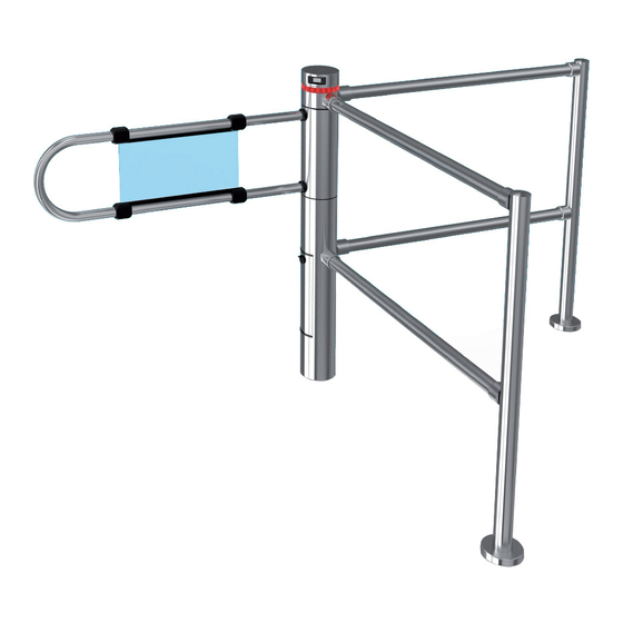
- Page 3 This symbol shows which parts to tell users about. Description This product is made by Came S.p.A. in conformity with current safety laws. Bidirectional motor-powered swing-leaf turnstile, with removable aluminum body and upper cover with anodized scotch-brite finishing for a STAINLESS STEEL look.
- Page 4 Main components Insulation tube Inspection cover frame Inspection hatch Bushing-covering leaf Sliding flange Extension sleeve Upper cap Internal rotating tube Central column Luminous LED crown with support Dimensions (mm) 1200 ø 120 ø 120 1020 1320 (001PSSL90) (001PSSL120)
- Page 5 System feasibility Only skilled, qualified staff must install this product. Preliminary checks Before beginning, do the following: • Have in place a suitable dual pole cut-off switch with minimum contact openings of 3 mm, and section the power supply; • Set up suitable tubes and conduits for the electric cables to pass through, making sure they are protected from any mechanical damage;...
- Page 6 Standard installation Swing-leaf turnstile Control device Barrier Junction box Applicative examples...
- Page 7 Installing The following illustrations are mere examples. Consider that the space available where to fi t the operator and accessories will vary depending on the installation site. It is up to each installer to select the most suitable solution. Careful! Use hoisting equipment to transport and position the turnstile. During the pre-mounting and fastening stages, the turnstile could be unstable and it could tip over.
- Page 9 Preparing the site and the turnstile base Check that there are no dips in ground where you will anchor the turnstile. Position the anchoring base as shown in the drawing (the leaf is perpendicular to the wall). Mark the anchoring holes with a pencil.
- Page 10 Fastening the turnstile to the ground Position the base on the anchoring spot and level it, if necessary, by using the adjusting screws. Connect the line power supply to the card terminal housed in the back of the central column. Ref.
- Page 12 At this point of the mounting, use the control panel to check that the turnstile works properly (the direction of travel and speed), see the paragraph on the control panel functions.
- Page 13 Center the tube with the control panel.
- Page 14 Command and control electronics Description The control panel is powered at 24 V AC. The control devices and accessories are powered at 24 V. Careful! The accessories must not exceed 10 W overall. All connections are quick-fuse protected. Functions on input and output contacts and time and user management details, are set up and viewable on the software-managed control panel's display.
- Page 15 Terminals C-NO2 = open leaf warning (or contact for additional alarm. See F-70). Terminals C-NO1 = warns that leaf is closed. Control device TOR 300 - paired RBM84 - Access control. CRP - Came Remote A B GND 1 2 3 4 2 CX connection. Connection to Came Protocoll.
- Page 16 Command and control devices Stop button (N.C. contact) - For stopping the turnstile while excluding the automatic closing cycle. To resume movement, press the control button. N.B.: if the contact is unused, select 0 (Deacti- vated) in function F 1. Contact (N.O.) for opening devices.
- Page 17 Programming Description of programming commands Display for viewing The button is for functions and settings • entering the programming that are assigned via the • entering the single menus programming buttons. • confirming/memorizing the set value The key are for •...
- Page 18 Gestione. Setting the turnstile operating modes. ] Stand Alone operation; [ ] paired connection operation; [ ] operation from RBM84 access control; [ ] operation via CRP (Came Remote Protocol). F-50 Saving data. Saving registered users and all settings in the The function appears only with connected.
- Page 19 Function Descripton ( negative [ ] default values ) F-54 Direction of entry. Setting the direction of entry. ] Commands: on 2-3 counter-clockwise opening; on 2-4 closing. Safeties: on 2-CX and 2-CY they intervene in both rotations. ] Commands: on 2-3 clockwise opening; on 2-4 closing. Safeties: on 2-CX and 2-CY they intervene in both rotations.
- Page 20 Motors test Always start programming the turnstile from this procedure. Activate procedure A 2, see Functions detail table. After pressing, the waiting [ ] will - - - appear. Keeping the button pressed, check c l I that the turnstile performs a CLOCKWISE <...
- Page 21 Off set closing limit-switch After calibrating the travel, the Off set closing limit-switch operation allows you to further adjust the position of the closed leaf, as illustrated in the examples. Select F 57. Press < > ENTER ENTER to confirm. Press the >...
- Page 22 N.B.: when entering and deleting users, the numbers that appear fl ashing are available and usable numbers for entering new users (max. 150 users). Entering users Select U 1 < > ENTER Press ENTER to confirm. Select 1 to activate the entering of a user via transponder <...
- Page 23 List of registered users 101) 102) 103) 104) 105) 106) 107) 108) 109) 110) 111) 112) 113) 114) 115) 116) 117) 118) 119) 120) 121) 122) 123) 124) 125) 126) 127) 128) 129) 130) 131) 132) 133) 134) 135) 136) 137) 138) 139)
- Page 24 Paired connection Specifi c connections Connect the two TOR 300 control boards with the CAT 5 - U/ UTP - AWG 24 multi-pair woven unscreened cable to terminals A-B-GND. Connect all of the necessary devices onto TOR 300 control board of the your MASTER turnstile.
- Page 25 Transferring parameters from MASTER to SLAVE Only the following parameters are copied: - opening and closing maneuvering speeds; - opening and closing slow-down speeds; - opening and closing slow-down points; - slow-down and travel sensitivity; - calibrating speed. To transfer the parameters from MASTER to SLAVE control board, proceed as follows: <...
-
Page 26: Maintenance
MAINTENANCE Before doing any maintenance, cut off the power supply, to prevent any hazardous situations caused by acciden- tally activating the operator. To properly maintain the AISI 304 stainless steel, refer to the stainless steel cleaning part of the 119RW48 manual. -
Page 27: Dismantling And Disposal
At its premises CAME S.p.A. employs the UNI EN ISO 14001 compliant Environmental Management System, to certify that the environment is respected and safeguarded. Please continue safeguarding the environment. At CAME we consider it one of the fundamentals of our operating and market strategies. Simply follow these brief disposal guidelines:... - Page 28 Came S.p.A. Came S.p.A. Via Martiri Della Libertà, 15 Via Cornia, 1/b - 1/c 31030 Dosson di Casier Dosson di Casier 33079 Sesto al Reghena Sesto al Reghena Treviso Treviso - Italy Pordenone Pordenone - Italy (+39) 0422 4940 (+39) 0434 698111...
Need help?
Do you have a question about the SALOON40 and is the answer not in the manual?
Questions and answers