
Summary of Contents for Drip Drop ADA-2000-E
- Page 1 INSTALLATION MANUAL Version: 0809-UK ADA-2000-E DripDrop AB Pipers Väg 2C SE-170 73 Solna, Sweden ● ● Tel: +46 (0) 8 655 02 94 Fax: +46 (0) 8 655 02 91 ● www.dripdrop.se info@dripdrop.se ●...
-
Page 2: Table Of Contents
On delivery the packing box of the ADA2000E comes with the following ADA-2000-E......................... 0 items: DESCRIPTION ADA-2000-W ................. 2 DIMENSIONS AND MOUNTING ................3 1(one) I/O unit ADA-2000-E I/O-SIGNALS......................4 ELECTRICAL CONNECTIONS ................5 24 V DC..................5 OWER SUPPLY I/O- .................. -
Page 3: Description Ada-2000-W
Accessories and part numbers Description ADA-2000-W The ADA-2000-W is the I/O-board for the pump control PC-2000-W. All I/O-signals are connected via the ADA-2000-E, and the signal interface between the ADA-2000 and the PC-2000 is made through 3 separate band cables. Description... -
Page 4: Dimensions And Mounting
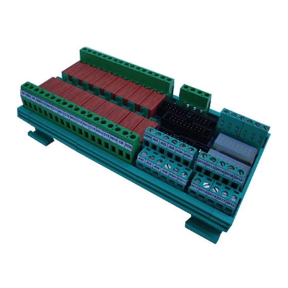
CEI 61000-4-8 30A/m Network frequency magnetic field CEI 61000-4-3 10V/m 26MHz-1GHz Immunity to radiated RF--fields ± 8kV Air discharge ADA-2000-E PC-2000-W CEI 61000-4-2 Cont. ± 4kV Electrostatic discharge immunity discharge SR EN 52022:2004 26MHz-1GHz Radiated emission Figure 2.1 shows an example of a standard DripDrop electrical panel for 2 pumps where the ADA-2000-W is mounted on a 35 mm DIN rail at the bottom of the control cabinet. -
Page 5: I/O-Signals
Signal Notes Level signal (Pressure signal) 4-20 mA separate I/O unit is used, the ADA-2000-E I/O board. The interconnection, of all Flow signal 4-20 mA input and output signals between the PC-2000-W and the ADA-2000-E are made P1 Motor current / Running confirm. -
Page 6: Electrical Connections
Connection ADA-2000-E ADA-2000-E Figure 4.1 shows a typical power supply connection to the PC-2000-W and ADA-2000-E units with battery back-up. If the utility power has problems with transients due to atmospheric discharges etc. a surge protection device should be installed at the 230 V AC supply line. -
Page 7: I/O- Signals Description
Page 9(14) Page 6(14) 4.6 Analogue inputs 4.2 I/O-signals description Digital outputs- the unit has 16 relay outputs which are galvanic separated to Inputs with pump current transducers for running confirmation allow that different voltages can be used. Each relay has an indicating diode which shows that the relay is activated All analogue devices are supplied with +24VDC, voltage to its positive terminal. -
Page 8: I/O- Signal Connections
Page 7(14) Page 8(14) 4.3 I/O-signal connections 4.4 Digital inputs and counters All digital input signals are supplied with 24 VDC control voltage. All digital inputs are opto isolated. All inputs have a corresponding LED showing the status. ¨ Figure 4.4 Digital input and counters configuration. Earth 4.5 Digital outputs The 16 digital outputs are output relays with a maximum load of 250 VAC1 / 6...
Need help?
Do you have a question about the ADA-2000-E and is the answer not in the manual?
Questions and answers