Table of Contents
Advertisement
Quick Links
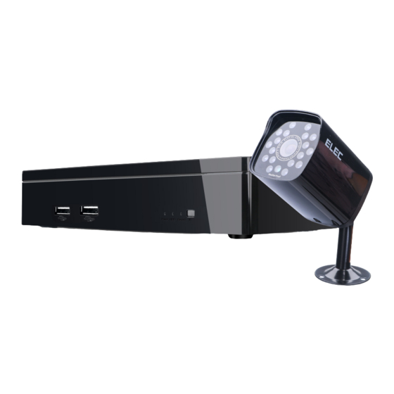
ELEC HL Series DVR User Manual
Welcome
Thank you for purchasing ELEC HL Series DVR. This user manual will help you to install and
operate our DVR with details. Please read this user manual thoroughly in order to get the
most out of ELEC product.
This user manual is applicable to ELEC HL Series DVR. Pictures, images and all other
information hereinafter are for description and explanation only. Slight difference may be
found in the user interface due to upgrade or other reasons. In such case, please refer to the
actual item. Also, the information contained in this user manual is subject to change, without
1
Advertisement
Table of Contents

Summary of Contents for Elec HL Series
- Page 1 ELEC HL Series DVR User Manual Welcome Thank you for purchasing ELEC HL Series DVR. This user manual will help you to install and operate our DVR with details. Please read this user manual thoroughly in order to get the most out of ELEC product.
- Page 2 To check the latest version of ELEC HL Series DVR, please visit our website www.elec.com Should you have any questions or concerns, please contact our support team by emailing aomgc@annigroup.com or sending messages to our Skype account: ELEC System Support.
-
Page 3: Table Of Contents
Table of Contents Chapter 1. Introduction......................4 Chapter 2. Installation.........................4 2.1 Front Panel........................5 2.2 Rear Panel........................6 2.3 Proper Cable Connection....................7 2.4 Soft Keyboard........................ 9 Chapter 3. Getting Started......................10 3.1 Start up DVR........................ 10 3.2 Shut Down DVR......................10 3.2.1 Standard Shutdown.................. -
Page 4: Chapter 1. Introduction
Chapter 10. Appendix....................... 55 Chapter 1. Introduction ELEC HL DVR is an excellent digital monitoring equipment that’s designed for security protection. It has embedded the LINUX operating system which is more stable. Armed with standard H.264 codec and unique spatial and temporal filtering algorithm, ELEC DVR realizes... -
Page 5: Chapter 2. Installation
As a safe and protection system, you can expect remote control, recording & playback, and backup, motion detection, alarm linkage, etc from ELEC HL DVR. Chapter 2. Installation Please be acquainted with ELEC HL DVR installation and its components first. 2.1 Front Panel The controls on the front panel include: 1. -
Page 6: Rear Panel
2. Power: Power indicator switches to red when the DVR is powered on. 3. HDD: HDD indicator switches to green when the hard drive is active. 4. Record: Record indicator flashes rapidly (green) when the DVR is recording. 2.2 Rear Panel The controls on the rear panel include: Item Description... -
Page 7: Proper Cable Connection
HD-Out HD output connector VGA interface for monitor connection Network RG45 network connector for internet connection DC power input connector 2.3 Proper Cable Connection Step 1: Connect monitor (TV Set, PC Monitor, etc) to DVR by VGA/HDMI/BNC cable. Note: 1. If you connect TV set by HDMI or VGA cable, please make sure that you switch TV set to corresponding HDMI or VGA input mode (also called RGB or PC in some TV sets). - Page 8 BNC cable VGA Cable...
-
Page 9: Soft Keyboard
Step 2: Connect a USB mouse to USB interface at the DVR’s front panel. Step 3: Connect the power supply to the DVR on the rightmost interface (DC interface on the rear panel). And plug DVR power supply into an electrical socket. Step 4: Connect the camera to DVR and power supply. -
Page 10: Chapter 3. Getting Started
Confirm selection. Input space(s). Delete the character in front of the cursor. Change between uppercase and lowercase. Change between uppercase and lowercase. Others: Numbers, symbols, letters. Chapter 3. Getting Started Proper startup and shutdown procedures are vital to extend the life of DVR. 3.1 Start up DVR After proper installation, plug the DVR power supply into an electrical outlet. -
Page 11: Forced Shutdown
Step 1: Right click on the preview screen. Step 2: Click on “Logout”. Step 3: Click the drop-down list and choose “Shutdown”. Step 4: Click on “OK”. 3.2.2 Forced Shutdown Cut out the DVR power directly. (It may cause data loss, please be cautious of using this method.) Remark: If there is an abnormal outage, the DVR would restore to its pre-status... -
Page 12: Chapter 5. Login
Step 1: Enable Cloud Service, so the DVR can be remotely accessed. Step 2: Turn on or off “Do not prompt anymore” according to your own needs. Step 3: Click “Next Page”, scan QR code to download Lynkn Pro app on your Android or IOS device. -
Page 13: Login
5.1 Login No password has been set for both of the users. When the login interface shows up, choose the User Name, leave the password field empty, then click “OK”. 5.2 Logout Step 1: Right click on the preview screen. Step 2: Click on “Logout”. -
Page 14: Chapter 6. Live View
Chapter 6. Live View The DVR enters into multiple-screen preview mode automatically after login. On the preview interface, it shall display date, time, channel title, recording and alarm status for each screen. Under normal circumstance, it displays channel number, channel recording sign, channel audio sign. -
Page 15: Playback
Right click on the preview screen, click on “Main Menu” to view different operations of ELEC HL Series DVR. Check each operation below. Remark: 1. If you need to exit from a certain page, just right click on the screen. -
Page 16: Playback Toolbar Introduction
7.1.2 Playback Toolbar Introduction Remark: “Previous Frame” and “Next Frame” are not available while playing back. However, those buttons can be useful when playback is paused. Single frame playback and backspacing every 2 seconds are supported. The controls of the playback interface include: Button Function Button... -
Page 17: Record Mode
● Tap “Full Screen” to playback in full-screen mode 7.2 Record Mode Path: Main Menu->Record Mode 7.2.1 Digital Path: Main Menu->Record Mode->Digital In this field, channel status and channel type can be viewed or edited. A. Channel Status: View each camera’s resolution, frame rate, connection status. B. -
Page 18: Record
You could use the following parameters to filter the records. Channel: Choose the desired channel number or all. File Type: All, Alarm, MD (Motion Detection), Alarm/MD, Manual, General. Type: Read/Write. Start Time, End Time. Backup Format: H264, AVI. Step 2: Left click “Detect” to select the external storage device for backup. Step 3: Click “Backup”. - Page 19 This function allows you to double backup recorded files, which equals to record the video into the two hard disks. Under such circumstance, the DVR needs to be installed with 2 hard disks simultaneously. One is the read/write disk, the other one is redundant disk. C.
-
Page 20: Hdd Manage
Choose Monday, Tuesday, Wednesday, Thursday, Friday, Saturday, Sunday or All. G. [ Period] ELEC DVR only records during the set time period. You can set multiple time periods up to 4. The time period can be intermittent, consecutive and repeated. - Page 21 HDD Information: You can check “Space, Status, Property, Req./Rem”. Format HDD: If the HDD memory is full, format HDD could make it re-utilized. Remark: 1. A DVR without a hard drive can only provide you with viewing, but not recording or playback.
-
Page 22: System Info (The Upside Down Exclamation Mark Of "!")
Step 2: There are two cables linked to DVR mother board. The one with a smaller interface is the SATA cable, the one with a bigger interface is the power cord. Hook up these two cables to corresponding hard drive’s interface. Step 3: Put HDD inside the DVR and keep it in a fixed position. -
Page 23: Hdd Info
7.3.1 HDD Info Path: Main Menu->the upside down exclamation mark of “!”->HDD Info Display all the related information of HDD. 7.3.2 LOG Path: Main Menu->the upside down exclamation mark of “!”->LOG Display system events like Login, Logout, Shutdown. You can also remove all logs by clicking “Remove”. -
Page 24: Alarm Set
7.5.1 Alarm Set Path: Main Menu->Alarm Setting->Alarm Set A. Motion Detection In order to turn on motion detection, please follow the instructions below: Step 1: Go to Main Menu->Record Mode->Record. - Page 25 Step 2: Set the relevant information. Channel: Select All; Week: Select All; Turn off Regular, open Detect; Then click OK. Step 3: Go to Main Menu->Alarm Setting->Alarm Set. Step 4: Click “Motion”. Select “All” channel, Toggle on “Enable”, then click “Advanced”. Step 5: Set all relevant factors, as shown in the following content.
-
Page 26: Abnormality
A. Show messages: A red icon of little bouncing person will appear on the relevant channel when motion is detected. B. Send Email: Send email alerts to assigned email address. C. Buzzer: Certain of our DVR models can produce buzz when motion is detected. D. -
Page 27: General
7.6.1 General Path: Main Menu->Setting->General You can view or edit general settings. The operations in this field include: System Time: View or correct system time. DST: Set DST. Date Format: Set date format as YYYY MM DD, MM DD YYYY, or DD MM YYYY. Language: English or Chinese. - Page 28 Purpose: Set parameters of encoding to realize high-quality playback and remote access. Remark: Before you start, please make sure a hard disk drive has been installed. If not, please install one in accordance with the instructions. (Refer to 7.2.4) (1) Independent Channel Encode Single Channel Encode You can set the following parameters.
- Page 29 Copy and paste channel encode Step 1: Choose Channel 1, set the parameters. (Refer to Single Channel Encode) Step 2: Click “Advanced”, then click “Copy”. Choose channel 2, then click “OK”. Step 3: Set other channels using the same method. (2) Extra Stream Set Applicable to client-end and mobile phone monitoring.
-
Page 30: Account
7.6.3 Account Path: Main Menu->Setting->Account You can manage different users, user group, and its authority. To be specific, Add User, Add Group, Delete User, Delete Group, Modify User, Modify Group, Modify Password are all supported. Modify Password Step 1: Choose the user name for password modification. Step 2: Click “Modify Pwd”. -
Page 31: Rs232
7.6.4 RS232 Path: Main Menu->Setting->RS232 The RS232 serial port is used for debugging and upgrading. You can view or edit the setting for Parity, Data Bits. Stop Bits, etc in this field. 7.6.5 Advanced Path: Main Menu->Setting->Advanced View or edit the settings for AutoMaintain, Import/Export, Restore, Upgrade. A. - Page 32 B. Import/Export Export log and configuration parameters. Import is also supported. C. Restore Restore the default settings. Just toggle on the related button and it will restore to the default setting. After the set, click “OK” to save the configuration. D.
-
Page 33: Network Setting
Upgrade directory or file 7.7 Network Setting Path: Main Menu->Network Setting... -
Page 34: Network
7.7.1 Network Path: Main Menu->Network Setting->Network View or edit LAN, PPPoE, Wifi, or Wireless Configuration. A. LAN (Local Area Network) DHCP Enable: Toggle on to obtain IP address automatically. IP Address: Default Value 192.168.1.18. Subnet Mask: Default Value 255.255.255.0. Gateway: Default Value 192.168.1.1. Remark: Set the DVR's IP address and router’s on the same LAN. - Page 35 C. Wifi (Connect to wireless router via wireless module) [Search]: Click it to search all the available wireless device. [Enable]: Turn on. [DHCP Enable]: Toggle on to obtain the IP address of Wifi automatically. [SSID]: Wireless LAN name. [Password]: The router password. [IP Address]: Set IP address.
-
Page 36: Net Service
access, and the equipment configuration) [Enable]: Toggle on (green). [Type]: Dial Type. Default: Auto. [Wireless AP]: 3G Access Point. Default: AccessPoint. [Dial Number]: 3G Dial Number. Default: #777 [User Name]: 3G user name for the dial. Default: ctnet@mycdma.cn [Password]: Password for dial-up user. [IP Address]: IP address obtained by dialing. - Page 37 [Enable]: Switch on or off. [Domain Name]: The domain name registered at the service provider that provides the domain name resolution. [User Name]: The account registered in the domain name resolution service providers. [Password]: Registered password. B. UPNP (Universal Plug and Play. This protocol conducts automatic port forwarding on the router.) Path: Main Menu->Network Setting->Net Service->UPNP Remark:...
- Page 38 C. ARSP Path: Main Menu->Network Setting->Net Service->ARSP [Type]: Select DNS. [Enable]: Turn on. [Server IP]: IP address of DDNS server. [TCP Port]: Input TCP port. [HTTP Port]: Input HTTP port. [User Name]: Input the user name of the login DDNS server. [Password]: Input the corresponding password.
- Page 39 D. RTSP: Real Time Streaming Protocol Path: Main Menu->Network Setting->Net Service->RTSP [Enable]: Switch on or off the RTSP function. [Server IP]: The default port is 554. E. FTP (File Transfer Protocol. Upload alarm video to FTP server when the alarm occurs) Path: Main Menu->Network Setting->Net Service->FTP [Enable]: Switch on or off the FTP function.
- Page 40 F. NTP Path: Main Menu->Network Setting->Net Service->NTP [Enable]: Switch on or off NTP function. [Server IP]: The IP address of the installed NTP server PC. [Port]: The default port is 123. It can be changed on the basis of the actual NTP server port settings.
-
Page 41: Cloud Service
7.7.3 Cloud Service Path: Main Menu->Network Setting->Cloud Service Cloud service must be enabled in order to remotely view on a mobile device. Device ID can also be found in this field. 7.7.4 EMAIL Path: Main Menu->Network Setting->EMAIL [Enable]: Switch on or off “Enable”. [SMTP server]: SMTP server address for your email service provider. -
Page 42: Chapter 8. Shortcuts
[Title]: This title serves as the “subject” when you receive an email alert. Remark: To send an email alert, you need to set relevant information in “Network” field first. Step 1: Make sure the DVR obtains the IP address automatically. Go to Main Menu-> Network Setting->Network->DHCP Enable (Toggle on). -
Page 43: Horizontal Shortcuts
Main Menu: Refer to Chapter 7. View 1: View 1 camera at a time. View 4: View 4 cameras at a time. Startup Wizard: Refer to Chapter 4. Tour: When the alarm is triggered, selected channel will start for a tour. Coaxial control: View or edit the settings for Zoom, Focus, Iris or PTZ trace, etc. -
Page 44: Close Record
8.2.1 Close Record Click it, the DVR would stop recording. 8.2.2 Playback Refer to 7.1. 8.2.3 PTZ Setting The PTZ’s function is up to the PTZ protocol, in other words, it is determined by PTZ dome that the user bought. PTZ setting interface is as shown below. [PTZ Direction]: Control PTZ to rotate, which supports 8 directions control. - Page 45 wheel to adjust camera’s magnification. [Set]: Enter into “PTZ Config” menu. A. Preset: Set certain orientation as the preset point. The PTZ shall rotate to that position automatically when calling the preset point value. B. Tour: Set Preset value, Interval, Patrol No. In this field, you can add, delete a preset point, and delete tour.
- Page 46 D. Border: Control the border turn to left or right. Preset setup Step 1: Turn PTZ to the position you want, click “set”. Step 2: Click “Preset”, input preset value, interval, Patrol No. Step 3: Click “Set”. Conclusively, the preset value corresponds with the position you set. Call preset Step 1: Click “page switch”...
-
Page 47: Color Setting
8.2.4 Color Setting The parameters of the color setting include Brightness, Contrast, Saturation, Hue, Gain, Horizon Sharpness, Vertical Sharpness, 2D Noise Reduction, 3D Noise Reduction. You can adjust color settings to meet your needs. Brightness: The larger the number, the brighter the video. Contrast: The larger the number, the higher the contrast. -
Page 48: Remote Access On Pc
9.1 Remote Access on PC Step 1: Open IE browser (not Microsoft Edge or any other browser) on your PC and access to http://cloud.elec.com Step 2: Click “Download” and wait for the ActiveX control downloading. Step 3: Install the ActiveX control on your computer. (Close IE browser while installing) -
Page 49: Remote Access On Mobile Phone
Step 4: After the installation, re-open IE browser and access to http://cloud.elec.com Step 5: Retrieve Device ID. Right click on the DVR’s initial interface. Go to Main Menu->System Info (the upside down exclamation mark of “!”)->Version ->Lynkn ID (Also serves as Device ID). -
Page 50: Remote Control On The Web
Step 3: Add DVR to the Lynkn Pro app. Click “+” sign in the upper right corner, then click “DVR”. Tap on “Manually Add”, input: Device ID (Lynkn ID), Username (admin by default), Password (Leave it empty). Then click “Save”. Remark: You can also click “LAN Search”... - Page 51 Step 3: Click “Install” to download control. After download, install the control on your computer. (Close IE browser while installing) Step 4: Re-open IE browser and input DVR’s IP address. Step 5: Input Username (admin) and password (leave it empty) on the pop-out interface. Then click on “Login”.
-
Page 52: Remote Control On Cms
9.4 Remote Control on CMS Remark: Be informed the CMS software is optimized for LAN (Local Area Network) access. Step 1: Make sure the device and computer are on the same local area network. Step 2: Download CMS software and launch it on your computer. Download link: https://www.dropbox.com/s/h8vct74q246oyjd/English%20version%20CMS.rar?dl=0 Step 3: Login Open CMS software and input the User name and password. - Page 53 Step 4: Local Network Setting Note: The LAN settings on DVR and CMS must be synchronized to realize remote control on CMS. Choose Realtek PCIe GBE Family Controller in “Network Adapter” field. Then all the relevant information will be inputted automatically. Click “OK”. Step 5: Add the DVR device to CMS.
- Page 54 Name (random), Login Type (IP), User name (admin by default), Password (leave it empty) and click “Save”. Remark: Choose “Cloud” in “Login type” field to gain remote access with Cloud ID. Step 6: The added device will be shown in the left column, right click the device name, then click “Open All Substream”...
-
Page 55: Chapter 10. Appendix
● Please refer to http://elec.com/en/detail-72.aspx to learn answer about FAQ. ● Please feel free to visit our official website at www.elec.com to learn more information about our DVR. Thanks for reading and your trust in ELEC.
Need help?
Do you have a question about the HL Series and is the answer not in the manual?
Questions and answers
I bot a system several years ago, played with it some, never installed at that house. I am ready to try again, hooked up everything (I assume HDMI cable is equal to usingVGA cable, cause I only habe HDMI) but I cannot get it to work. Power light shows DVR is on. I suspect the remote. It was stored with no batteries channel is clean, installed new batteries, but get no response from the DVR. How can I know if router is bad? (The light at front does not light at any time, any button push)