Table of Contents
Advertisement
Quick Links
650 Series
AC Drive
Frame 1, 2 & 3
Product Manual
HA464828U003 Issue 3
Compatible with Version 4.4 Software onwards
Eurotherm Drives warrants the goods against defects in design, materials and
workmanship for the period of 12 months from the date of delivery on the terms
detailed in Eurotherm Drives Standard Conditions of Sale IA058393C.
Eurotherm Drives reserves the right to change the content and product specification
© Copyright Eurotherm Drives Limited 2003
All rights strictly reserved. No part of this document may be stored in a retrieval system, or transmitted in any form or
by any means to persons not employed by a Eurotherm Drives company without written permission from Eurotherm
Drives Ltd.
Although every effort has been taken to ensure the accuracy of this document it may be necessary, without notice, to
make amendments or correct omissions. Eurotherm Drives cannot accept responsibility for damage, injury, or expenses
resulting therefrom.
WARRANTY
without notice.
E U R O T H E R M
D R I V E S
Advertisement
Table of Contents

Related Manuals for Eurotherm Drives 650 Series

Summary of Contents for Eurotherm Drives 650 Series
- Page 1 All rights strictly reserved. No part of this document may be stored in a retrieval system, or transmitted in any form or by any means to persons not employed by a Eurotherm Drives company without written permission from Eurotherm Drives Ltd.
- Page 2 Application Risk The specifications, processes and circuitry described herein are for guidance only and may need to be adapted to the user’s specific application. Eurotherm Drives does not guarantee the suitability of the equipment described in this Manual for individual applications.
- Page 3 650 Quick Start Mount the drive vertically in a lockable cubicle. Is the drive to operate in Local (using the keypad) or Remote Control? If Remote Control, make Control Connections. Make Power Connections. Power-on and follow the Quick Set-Up procedure. Apply a small setpoint.
-
Page 4: Table Of Contents
Contents Contents Page Chapter 1 E T T ING T A R T E D Introduction....................1-1 Equipment Inspection ....................1-1 Storage and Packaging ..................... 1-1 About this Manual..................1-1 • Software Product Manual................ 1-1 Chapter 2 VE R VIE W O F T HE R IVE Component Identification................2-1 Chapter 3... - Page 5 E P A I R Routine Maintenance ..................8-1 Repair......................8-1 Saving Your Application Data ..................8-1 Returning the Unit to Eurotherm Drives............... 8-1 Disposal ........................8-1 Chapter 9 E C HNIC A L P E C IF IC A T IO NS Understanding the Product Code ................
- Page 6 Contents Contents Page Environmental Details ....................9-3 Power Details......................9-3 User Relay ........................ 9-3 Electrical Ratings ....................... 9-4 Analog Inputs/Outputs ....................9-5 Digital Inputs ......................9-5 Digital Outputs ......................9-5 Cabling Requirements for EMC Compliance .............. 9-5 Internal Dynamic Braking Circuit ................9-6 External Brake Resistor ....................
-
Page 7: Getting Started
ETTING TARTED Introduction The 650 Series AC Drive provides simple, compact, and low-cost speed control for 3-phase induction motors. It operates as an Open-loop Inverter (V/F Fluxing). This manual describes the low-power end of the 650 product range for the following motor... -
Page 8: An Overview Of The Drive
Figure 2-1 View of Component Parts (Frame 1 illustrated) Main drive assembly Control terminals Keypad Volt-free relay contacts DIN clip/fixing bracket Product rating label Terminal cover Motor thermistor terminals Power terminals RS232 port - P3 (optional) Motor cable screen clamp 650 Series AC Drive... -
Page 9: Nstalling The Rive
When mounting two or more 650 units together, these clearances are additive. Ensure that the mounting surface is normally cool. Be aware that adjacent equipment may generate heat and also have clearance requirements. Provided the minimum clearance for ventilation is maintained, 650 drives may be mounted side-by-side. 650 Series AC Drive... -
Page 10: Electrical Installation
Ensure that all wiring is electrically isolated and cannot be made “live” unintentionally by other personnel. The drive is suitable for use with both earth referenced supplies (TN) and non- earth referenced supplies (IT) when fitted with an internal ac supply EMC filter. 650 Series AC Drive... -
Page 11: Connection Diagram
(TN) and non-earth referenced supplies (IT) when 8 Re-fit the terminal cover. fitted with an internal ac supply EMC filter. IMPORTANT: Note that the 650 unit must be permanently earthed using two independent protective earth/ground incoming supply conductors. 650 Series AC Drive... -
Page 12: Control Wiring Connections
0 to 220/240V or 380/460V ac M3/W 0 to 240Hz 0 to 240Hz Reference Supply protective earth (PE). This terminal must be connected to a protective (earth) Terminal ground for permanent earthing. permanent earthing. permanent earthing. permanent earthing. 650 Series AC Drive... -
Page 13: Terminal Block Acceptance Sizes
Strip the wire insulation to 5-6mm (0.20-0.24 inches), or alternatively use wire-crimps. Insert a flat-bladed screwdriver, maximum blade size 3.5mm. The cage provides the correct force for a secure connection. IMPORTANT: DO NOT lever or turn the screwdriver. 650 Series AC Drive... -
Page 14: Optional Equipment
Keypad when correctly mounted. Assembly Procedure Cut-out Dimensions The drawing below can be photocopied actual size (100%) and used as a template. 72mm ± Template ± ± 54mm ± ± 15.5 Cut-out 26mm ± 650 Series AC Drive... -
Page 15: Fitting The Remote 6521/6901 Keypad
An actual size template is provided with the Keypad/6052 Mounting Kit. Template Figure 3-1 Mounting Dimensions for the Remote-Mounted Keypad 6521/6901 The 6901 keypad, supplied with 690+ products, may be remote mounted and connected to the 650 drive in the same way. 6901 650 Series AC Drive... -
Page 16: Rs485/Rs232 Communication Module
Receiver Input 3 kΩ minimum Impedance 7kΩ maximum 1200m (4000ft) 3 metres Maximum Cable Length 57.6kbaud 57.6kbaud Maximum Baud Rate 32 including slaves and masters 2: 1 master and 1 slave Maximum Number of only Units 650 Series AC Drive... - Page 17 SE01 to SE08. For Tag number information refer to the 650 Software Product Manual, available on the Eurotherm Drives website: www.eurothermdrives.com. Note: This Option can only be used on drives using software version 4.1 or higher. 650 Series AC Drive...
-
Page 18: Line Choke
Screws Screws (Aeff) (Aeff) (Aeff) (Aeff) (mH) (mH) (mH) (mH) (mm) (mm) (mm) (mm) (kg/lbs) (kg/lbs) (kg/lbs) (kg/lbs) 650 Frame 2, 3-phase, 400V, 0.37kW/0.5Hp 4.88 110 69 2.1/ * dimension is dependent of the air gap 650 Series AC Drive... -
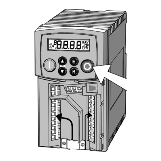
Page 19: Perating The
Note: If during the start-up routine the display shows either an alarm (indicated by the letter “A”) or a flashing Warning message, A typical alarm refer to Chapter 7: “Trips and Fault Finding”. 650 Series AC Drive... -
Page 20: Local Control Operation
The drive will operate as an open-loop drive. It is programmed to control an induction motor of equivalent power, current, and voltage rating to the drive. The drive's default parameters will operate effectively under most circumstances, however you may wish to refer to Chapter 6 to tune the drive to your system. 650 Series AC Drive... -
Page 21: The
Local Mode – Stops the drive. Trip Reset in all modes Navigation – Press and hold to toggle between Local and Stop Remote Control modes (refer to page 5.4) Trip Reset – Resets trip condition allowing drive to resume operation 650 Series AC Drive... -
Page 22: Display Indications
The current output frequency in Hertz SPEED SETPOINT The set point as a percentage of MAX SPEED Vac (rms) x √2 = dc link Volts DC LINK VOLTS (when motor stopped) MOTOR CURRENT The current load value in Amps 650 Series AC Drive... -
Page 23: The Menu System
The first visit to a menu after power-up will display the first parameter in each menu. On subsequent visits, you will be returned to the previously-displayed parameter for each menu. TRIPS MENU SERIAL MENU MISCELLANEOUS SETUP MENU 650 Series AC Drive... -
Page 24: How To Change A Parameter Value
Local Setpoint is displayed. Remote to Local Control: Hold this key down until the display shows REMOTE Hold this key down until the display spells Release the key to display LOCAL the Local Setpoint 650 Series AC Drive... -
Page 25: Password Protection
Navigate to the parameter (SET::SETP::ST99) and press the key. This toggles full or partial menu detail. The default setting of 0 provides partial menu detail. Set the parameter to 1 for full menu detail. 650 Series AC Drive... -
Page 26: Mmi Parameters
The time taken for the 650 output frequency to 0.0 to 3000.0s 10.0s ramp down from MAX SPEED to zero MOTOR This parameter contains the motor nameplate full- 0.01 to 999.99A product CURRENT load line current code dependent 650 Series AC Drive... - Page 27 Quadratic Torque in LAW, 12 is set to 0 (HEAVY DUTY) past Eurotherm Drives' When 11 is changed from LINEAR LAW to FAN manuals. LAW, 12 is set to 1 (NORMAL DUTY) 12 can be changed independently 650 Series AC Drive...
-
Page 28: P R O G R Amming Y O U R Applic At Io Nmmi Parameters
Determines the maximum positive and negative 0.00 to 300.00% 300.00% excursion (Limit) of the PID output PID SCALING This parameter represents an overall scaling factor -3.0000 to 3.0000 1.0000 which is applied after the PID positive and negative limit clamps 650 Series AC Drive... - Page 29 AOUT 1 SCALE -300.00 to 300.00% 100.00% SCALE OFFSET AOUT 1 OFFSET -300.00 to 300.00% 0.00% VALUE AOUT 1 0= FALSE ABSOLUTE (not absolute) 100% 1= TRUE (absolute) AOUT 1 VALUE CLAMP OUTPUT -300.0 to 300.0% 0.0% 650 Series AC Drive...
- Page 30 LOOP DISABLE MOTOR Disables the motor thermistor trip LOOP OVERTEMP INVERSE TIME Disables the inverse time trip LOOP DISPLAY Disables the display (keypad) trip LOOP (KEYPAD) DC LINK RIPPLE Disables the DC link ripple trip LOOP 650 Series AC Drive...
- Page 31 MIN SPEED Selects a mode to determine how the drive will 0=PROP.W/MIN. MODE follow a reference: Proportional : minimum limit, 1=LINEAR (used by Linear : between minimum and maximum. the 601 product) 650 Series AC Drive...
- Page 32 Setting this parameter to TRUE prevents editing of 0=FALSE LOCK parameter 1=TRUE Set this parameter to FALSE to edit parameter DETAILED MENUS Selects Full menu detail when TRUE. The 0=FALSE additional parameters in the Full menus are 1=TRUE indicated in this table by 650 Series AC Drive...
-
Page 33: Configuring Terminal 10 (Digital Input/Output)
Setpoint and Feedback, together with good transient performance. Proportional Gain ( 501) This is used to adjust the basic response of the closed loop control system. The PI error is multiplied by the Proportional Gain to produce an output. 650 Series AC Drive... -
Page 34: Auto Restart
(5 minutes or 4 x AUTO RESTART DELAY, whichever is the longer); or after a successful manual or remote trip reset; or by removing the Run signal (Terminal 7, DIN1). Refer to Chapter 7: "Trips and Fault Finding" - Hexadecimal Representation of Trips. 650 Series AC Drive... -
Page 35: Skip Frequencies
The skip frequencies are symmetrical and thus work in forward and reverse. Setting SKIP FREQUENCY or SKIP FREQUENCY BAND to 0 disables the corresponding band. Drive Frequency Skip band Skip Frequency Setpoint Drive Frequency Frequency 2 Frequency 1 Setpoint Drive Frequency Setpoint Frequency 1 Frequency 2 650 Series AC Drive... -
Page 36: Minimum Speed Mode
Function Block Function Block Function Block Function Block 50Hz Operation 50Hz Operation 50Hz Operation 50Hz Operation 60Hz Operation 60Hz Operation 60Hz Operation 60Hz Operation BASE FREQUENCY MOTOR DATA 1159 50Hz 60Hz MAX SPEED REFERENCE 50Hz 60Hz 650 Series AC Drive... -
Page 37: Power Dependent Parameters
16.00 A FIXED BOOST FLUXING 5.00 % 5.00 % 5.00 % 5.00 % ACCEL TIME REFERENCE RAMP 10.0 s 10.0 s 10.0 s 10.0 s DECEL TIME REFERENCE RAMP 10.0 s 10.0 s 10.0 s 10.0 s 650 Series AC Drive... -
Page 38: Rips And
The supply voltage is too high • Trying to decelerate a large inertia load too quickly; DECEL TIME time too short The brake resistor is open circuit UNDERVOLTAGE DC link low trip: Supply is too low/power down 650 Series AC Drive... - Page 39 The motor temperature is too high: OVERTEMP • Excessive load • Motor voltage rating incorrect • FIXED BOOST level set too high • Prolonged operation of the motor at low speed without forced cooling • Break in motor thermistor connection 650 Series AC Drive...
- Page 40 Product Code Error Switch unit off/on. If persistent, return unit to factory Calibration Data Switch unit off/on. If persistent, return unit to factory Error Configuration Data Press the key to accept the default configuration. If Error persistent, return unit to factory 650 Series AC Drive...
-
Page 41: Hexadecimal Representation Of Trips
Keypads (MMIs): Trips shown as MMI displays in the tables above, i.e. , can be disabled using the keypads in the TRIPS menu. Other trips, as indicated, can be disabled over the Comms. 6511 6901 6521 650 Series AC Drive... -
Page 42: Fault Finding
Motor will not run at switch-on Motor jammed Stop the drive and clear the jam Motor runs and stops Motor becomes jammed Stop the drive and clear the jam Open circuit speed reference Check terminal potentiometer 650 Series AC Drive... -
Page 43: Routine Maintenance And Repair
Repair There are no user-serviceable components. IMPORTANT: MAKE NO ATTEMPT TO REPAIR THE UNIT - RETURN IT TO EUROTHERM DRIVES. Saving Your Application Data In the event of a repair, application data will be saved whenever possible. However, we advise you to make a note of your application settings before returning the unit. -
Page 44: T Echnical Specifications
F = Internal Supply Filter fitted: Class A - 400V product Class B - 230V product Two digits specifying the livery: 00 = Standard Eurotherm Drives Livery 05 = Distributor Livery (01-04, 06-99 – Defined customer liveries) Characters speciifying the use of the Keypad:... -
Page 45: Catalog Number (North America)
230 (±10%) 50/60Hz 380 to 460V (±10%) 50/60Hz One character specifying the use of the Internal RFI Filter: 0 = Not fitted F = Internal Supply Filter fitted: Class A - 400V product Class B - 230V product 650 Series AC Drive... -
Page 46: Environmental Details
380-460V 3φ product -10000A User Relay Terminals RL1A, RL1B. Maximum Voltage Maximum Voltage 250Vac Maximum Voltage Maximum Voltage Maximum Current Maximum Current Maximum Current Maximum Current 4A resistive load Sample Interval Sample Interval 10ms Sample Interval Sample Interval 650 Series AC Drive... -
Page 47: Electrical Ratings
Maximum Motor dv/dt = 10,000V/μs. This can be reduced by adding a motor choke in series with the motor. Contact Eurotherm Drives for recommended choke details. Local wiring regulations always take precedence. Select cable rated for the drive. -
Page 48: Analog Inputs/Outputs
Screen to Earth Screen to Earth Both ends Both ends Drive end only Connection Connection Connection Connection 300 metres Output Choke Output Choke Output Choke Output Choke maximum * Maximum motor cable length under any circumstances 650 Series AC Drive... -
Page 49: Internal Dynamic Braking Circuit
(where fitted) allow easy connection to an external resistor. These resistors should be mounted on a heatsink (back panel) and covered to prevent injury from burning. Recommended Brake Resistors The following brake resistors are avialable from Eurotherm Drives: Brake Resistor Value : Frame 2 : 200Ω, 100W - CZ467714;... -
Page 50: Supply Harmonic Analysis (230V Filtered)
Drive Type Motor Power (kW) 0.25 0.37 0.55 0.75 Fundamental Voltage (V) Typical Motor Efficiency % Harmonic No. RMS Current (A) 10.3 Total RMS Current (A) 10.9 12.5 THD (V) % 0.3559 0.0972 0.5426 0.5733 0.6277 0.7055 650 Series AC Drive... -
Page 51: Supply Harmonic Analysis (400V Filtered)
0.55 0.75 Fundamental Voltage (V) Typical Motor Efficiency % Harmonic No. RMS Current (A) 12.9 11.1 Total RMS Current (A) 12.0 15.8 20.8 THD (V) % 0.1561 0.2158 0.2776 0.3859 0.4393 0.5745 0.6994 0.8111 0.9899 1.2110 650 Series AC Drive... -
Page 52: Supply Harmonic Analysis (230V Unfiltered)
Drive Type Motor Power (kW) 0.25 0.37 0.55 0.75 Fundamental Voltage (V) Typical Motor Efficiency % Harmonic No. RMS Current (A) Total RMS Current (A) 11.7 15.3 THD (V) % 0.5633 0.8016 1.0340 1.0944 1.4611 1.7778 650 Series AC Drive... -
Page 53: Supply Harmonic Analysis (400V Unfiltered)
0.55 0.75 Fundamental Voltage (V) Typical Motor Efficiency % Harmonic No. RMS Current (A) 12.7 11.0 Total RMS Current (A) 12.4 16.0 20.6 THD (V) % 0.1634 0.2209 0.2817 0.3569 0.4444 0.5886 0.7107 0.8896 1.0127 1.2138 650 Series AC Drive... -
Page 54: Ertification For The
It is recommended that UL Listed (JDDZ) non-renewable cartridge fuses, Class K5 or H; or UL Listed (JDRX) renewable cartridge fuses, Class H, are installed upstream of the drive. Motor Base Frequency The motor base frequency rating is 240Hz maximum. Field Wiring Temperature Rating Use 75°C Copper conductors only. 650 Series AC Drive... - Page 55 Supply Fuse Rating (A) Supply Fuse Rating (A) Supply Fuse Rating (A) (kW/hp) (kW/hp) (kW/hp) (kW/hp) 10 x 38mm 10 x 38mm 10 x 38mm 10 x 38mm 3.0/4 11.1 4.0/5 13.9 5.5/7.5 18.0 7.5/10 23.6 650 Series AC Drive...
-
Page 56: European Directives And The Ce Mark
European Directives and the CE Mark CE Marking for Low Voltage Directive When installed in accordance with this manual, the 650 Series AC Drive is CE marked by Eurotherm Drives Ltd in accordance with the low voltage directive (S.I. No. 3260 implements this LVD directive into UK law). -
Page 57: Certificates
DIRECTIVE) DIRECTIVE) the unit is used directive for as relevant electrical We Eurotherm Drives Limited, address as We Eurotherm Drives Limited, address as apparatus. below, declare under our sole responsibility below, declare under our sole responsibility equipment and that the above Electronic Products when... - Page 58 DIRECTIVE) DIRECTIVE) the unit is used directive for as relevant electrical We Eurotherm Drives Limited, address as We Eurotherm Drives Limited, address as below, declare under our sole responsibility below, declare under our sole responsibility apparatus. equipment and that the above Electronic Products when...
-
Page 59: Erial Ommunications Connection To The P3 Port
The drive MUST be earthed. Failure to do so could damage your communications ports. The drive MUST be earthed The port is an un-isolated RS232, 19200 Baud. Contact Eurotherm Drives for further information. The P3 port is located under the terminal cover and is used only by the remote-mounted RS232 Keypad. -
Page 60: Pplic At Io Ns
When you load an Application, the input and output parameters shown in these diagrams default to the settings shown. For alternative user-settings refer to the Software Product Manual, Chapter 1 "Programming Your Application". Key to Application Diagrams normally open contact (relay) normally open push-button 2-position switch normally closed push-button 650 Series AC Drive... -
Page 61: Application 1 : Basic Speed Control (Default)
12-2 Applications Application 1 : Basic Speed Control (default) 650 Series AC Drive... - Page 62 4mA = 0%, 20mA = 100% 10k Speed AIN1 SPEED SETPOINT A or V 0V = 0%, 10V = 100% Setpoint default source = 4-20mA RL1A DOUT3 HEALTH i.e. 0V = not healthy RELAY SOURCE User Relay RL1B 650 Series AC Drive...
-
Page 63: Application 2 : Auto/Manual Control
12-4 Applications Application 2 : Auto/Manual Control 650 Series AC Drive... - Page 64 4mA = 0%, 20mA = 100% A or V AUTO SETPOINT Manual AIN1 MANUAL SETPOINT default source 0V = 0%, 10V = 100% Setpoint = 4-20mA RL1A DOUT3 (relay) HEALTH i.e. 0V = not healthy RELAY SOURCE User Relay RL1B 650 Series AC Drive...
-
Page 65: Application 3 : Preset Speeds
12-6 Applications Application 3 : Preset Speeds 650 Series AC Drive... - Page 66 DIN2 DIN2 Preset Preset 0 0 0 0 1 1 1 1 2 2 2 2 3 3 3 3 4 4 4 4 5 5 5 5 6 6 6 6 7 7 7 7 650 Series AC Drive...
-
Page 67: Application 4 : Raise/Lower Trim
12-8 Applications Application 4 : Raise/Lower Trim 650 Series AC Drive... - Page 68 24V = run forward +24V AOUT DEMAND (0V = 0%, 10V = 100%) RAMP OUTPUT +10V REF +10V REF AIN2 Not Used AIN1 Not Used RL1A DOUT3 (relay) RELAY SOURCE HEALTH i.e. 0V = not healthy User Relay RL1B 650 Series AC Drive...
-
Page 69: Application 5 : Pid
12-10 Applications Application 5 : PID 650 Series AC Drive... - Page 70 4mA = 0%, 20mA = 100% (Preset 0) 10k Speed AIN1 PROCESS SETPOINT 4mA = 0%, 20mA = 100% (Preset 0) A or V Setpoint default source = 4-20mA RL1A DOUT3 (relay) RELAY SOURCE HEALTH i.e. 0V = not healthy User Relay RL1B 650 Series AC Drive...
Need help?
Do you have a question about the 650 Series and is the answer not in the manual?
Questions and answers