Table of Contents
Advertisement
Advertisement
Table of Contents

Summary of Contents for LNS Turbo HB
- Page 1 Instruction manual LNS SA CH-2534 Orvin www.LNS-group.com...
-
Page 3: Table Of Contents
3.3. Belt Tensioning – How to tension the belt ..................3-4 3.4. Belt removal and installation ......................3-5 3.6. Belt assemblies ..........................3-9 3.6.1. Standard and Heavy Duty belts ....................3-9 3.6.2. Super Heavy Duty belts ......................3-10 TURBO HB... - Page 4 5.2. Chip stripper bar ..........................5-4 5.3. Spare parts ............................5-5 5.3.1. Layout of the elements – Direct drive version ................5-5 CHAPTER 6: APPENDICES ..................6-1 Appendix A: Ordering form ........................6-2 Appendix B: Address LNS ........................6-3 TURBO HB...
-
Page 5: Chapter 1: Introduction
CHAPTER 1: INTRODUCTION CHAPTER 1: INTRODUCTION TURBO HB... -
Page 6: Basic Introduction
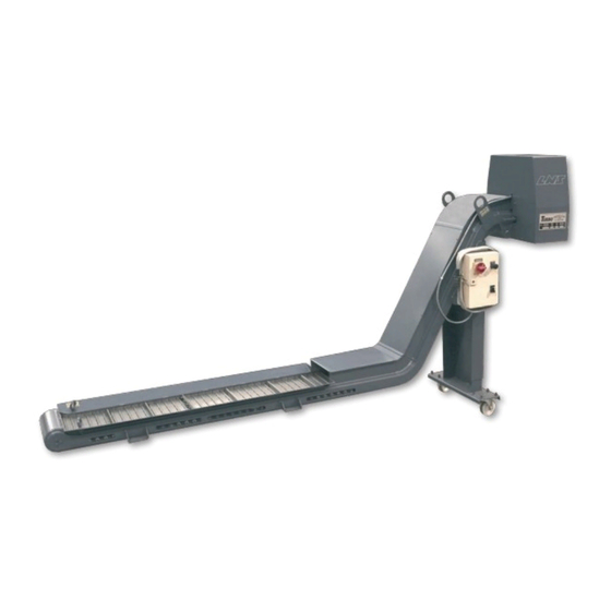
For further information, contact LNS. The TURBO HB conveyor was specifically designed to handle a wide variety of materials and applications where filtration is not required. Its simple yet robust construction ensures it offers a long, continuous, trouble free operation in the most demanding of today’s machining environments. -
Page 7: Rights
All information contained in this manual is entented to be correct, however information and data in this manual are subject to change without notice. LNS SA makes no warranty of any kind of regard to this information or data. Further, LNS SA is not responsible for any omissions or errors or consequential damage caused by the user of the product. -
Page 8: Characteristics
1.3.1. Floor plans Each conveyor varies in size depending on the machine tool it is designed to fit to. Above is a general diagram which can be used to help in communications with LNS SA regarding size queries and enquiries. Drawing... -
Page 9: Chapter 2: Setting Into Operation
CHAPTER 2: SETTING INTO OPERATION CHAPTER 2: SETTING INTO OPERATION TURBO HB... -
Page 10: Transportation
All shipping documents including this manual are also secured to the pallet. Regardless of the type of packaging, the un-creating and lifting instructions recommended by LNS SA must be observed in order to prevent any injuries to persons and damages to objects. -
Page 11: Lifting The Conveyor
Otherwise points under the system are marked with arrows for safe, balanced, lifting points for fork trucks to lift the conveyor system. Always read the weight on the conveyor and check it against the capacity of the lifting equipment before attempting to lift: TURBO HB... -
Page 12: Fitting The Castors
Please see the drawing below for the castor assembly: Designation Description M10 bolts M10 lock washers M10 washers Castor M10 nuts Castor plate TURBO HB... -
Page 13: Safety Devices
2.5.1. Description The TURBO HB conveyor has been designed with a focus on maximum safety during its handling and complies with all EC requirements. Safety covers and devices make access to the moving parts of the conveyor impossible during operation. -
Page 14: Installation Safety
In order to ensure the proper installation of the conveyor several steps must be taken. These steps are listed below. It is possible to purchase these parts from LNS if required. Speak to your local LNS representative for further details: 1) Suitable guarding must be used between the waste receptacle and the conveyor to ensure no access to the moving belt is possible when the receptacle is in place (labeled 4 below). -
Page 15: Security Analysis For The Correct Incorporation
Evaluate and assess the risks associated by using the machine programming risks operation risks risks of use maintenance risks • Choose methods of protection : the use of protective devices the introduction of signals compliance with safe work procedures TURBO HB... -
Page 16: Installation And Startup
For the electrical connection, please see section 2.6.4. and, if an electrical control is supplied, the electrical drawing in side the conveyors electrical box. If an Air header is supplied the pneumatic (airline) must be connected to the Air header inlet as indicated in chapter 5, section 5.1. TURBO HB... -
Page 17: Electrical Connection
2.6.4. Electrical connection Particular attention should be given to the handling of electrical elements because of risks of electrocution. In case of possible electrical malfunctions, it is advisable to contact LNS or their local representative. It is strictly prohibited to make adjustments as long as the conveyor is under electrical power. -
Page 18: Setting The Voltage Of The Motor - Direct Drive Version
If an electrical control is supplied then please see the electrical drawing inside the control panel for specific details. If any faults with the conveyor control occur or further information is required please consult your local LNS agent. TURBO HB... -
Page 19: Chapter 3: Conveyor Belt
CHAPTER 3: CONVEYOR BELT CHAPTER 3: CONVEYOR BELT TURBO HB... -
Page 20: Belt Direction
Please read the safety instructions provided at the beginning of this manual before Starting the conveyor DISCHARGE TURBO HB 3.2. Belt tensioning – Checking the tension Please read the safety instructions provided at the beginning of this manual before carrying out any maintenance on the conveyor. - Page 21 Check to see that the clutch body is square to the bearing mounting bracket. If it is not, this will generally indicate which direction the belt is off on side to side tension. Once it is determined that re-tensioning of the belt is necessary, the following procedure should be followed: TURBO HB...
-
Page 22: Belt Tensioning - How To Tension The Belt
NOTE: Belts with discharge heights in excess of 1200mm or load lengths in excess of 2500mm may require higher torque settings application or different incline angles can also affect the required torques settings. Contact LNS Turbo if assistance is needed. Torque Guide •... -
Page 23: Belt Removal And Installation
5. Slide the drive shaft toward the tail of the conveyor as far as the adjusting slots for the pillow block bearings will allow. This will provide maximum slack in the belt. Belt tensioning Pillow Block adjusting screws bearing mounting bolts Pillow Block Locking nut bearing TURBO HB... - Page 24 As the last of the belt begins to run out faster, don't attempt to stop it; just stand clear and let it run out onto the floor. Note that the belt was moved in the direction opposite normal belt travel. TURBO HB...
- Page 25 17. Reverse steps 1 through 7. When carrying out step 2 in reverse ensure that the motor is not raised too high as to cause unnecessary stress on the chain. The chains should be tight but there should move together around 5mm when squeezed. Also ensure that all lock nuts are secured before testing. TURBO HB...
- Page 26 20. Re-connect power and test run the conveyor. The belt should run freely and the only sound should be a subdued clicking as each hinge plate passes over the drive sprocket. TURBO HB...
-
Page 27: Belt Assemblies
Hex head screw Lock washer Tail disc (on inside of frame) Hinge plate w / cleat Hinge plate Hinge plate / w / wiper cleat Wiper Washer Hex head screw Side wing Roller Washer Link pin Cotter pin TURBO HB... -
Page 28: Super Heavy Duty Belts
Side wing – right hand Side wing – left hand Hinge plate w / wiper cleat Wiper Washer Hex head screw Link plate Roller link assembly Link plate – roller assembly Roller Split bushing Link pin Cotter pin (where not crimped) TURBO HB... -
Page 29: Chapter 4: Maintenance
CHAPTER 4: MAINTENANCE CHAPTER 4: MAINTENANCE TURBO HB... -
Page 30: Periodic Inspection
Switch of the power supply to the system before commencing any maintainance work. The TURBO HB conveyor has been designed to be low maintenance, however, the following periodic checks should be completed at the recommended service intervals to ensure continued and trouble-free operation. -
Page 31: Chapter 5: Options
CHAPTER 5: OPTIONS CHAPTER 5: OPTIONS TURBO HB... -
Page 32: Air Header
Please read the safety instructions provided at the beginning of this manual before handling the following devices. Do not drill holes in the conveyor without consulting LNS beforehand as this will invalidate the warranty as serious damage can occur. Depending on the machine, customer preference and application an air header may or may not be supplied with your conveyor. - Page 33 Air requirement chart (m3/hour) Belt width (mm) 10.9 14.8 19.7 23.4 pressure 10.4 12.1 16.1 21.6 25.8 (Bar) 11.2 112.9 17.5 23.3 27.9 12.1 13.9 18.7 25.0 29.9 12.7 14.8 19.9 26.5 31.6 10.2 13.4 15.5 20.9 27.9 33.3 TURBO HB...
-
Page 34: Chip Stripper Bar
Do not drill holes in the conveyor without consulting LNS beforehand as this will invalidate the warranty as serious damage can occur. Depending on the machine, customer preference and application a chip stripper bar may or may not be supplied with your conveyor. -
Page 35: Spare Parts
CHAPITRE 5: OPTIONS 5.3. Spare parts Without the written consent of LNS SA, no addition or modification of the machine or spare parts can be undertaken. LNS SA assumes no responsibility when using spare parts which were not provided by LNS 5.3.1. - Page 36 Baffle LH Top cover load Baffle gusset Track incline RG Top cover incline Drive cover Please note that the appearance of the conveyor may vary and some components may not be present on your conveyor due to application design TURBO HB...
-
Page 37: Chapter 6: Appendices
CHAPTER 6: APPENDICES CHAPTER 6: APPENDICES Appendix A : Ordering form Appendix B : Address LNS TURBO HB... - Page 38 CHAPTER 6: APPENDICES Appendix A: Ordering form This form should be photocopied, duly filled out, and returned to your retailer or nearest LNS SA agent Company name: Person in charge: Address: ZIP: City: Country: Phone: Fax: Type of device: Serial number: Qty.
-
Page 39: Appendix B: Address Lns
CHAPITRE 6: APPENDICES Appendix B: Address LNS LNS Agencies SCHWEIZ / SUISSE LNS S.A. sales@Lns-world.com service@Lns-world.com Headquarter www.Lns-group.com Case postale 33 CH – 2534 ORVIN TEL. +41 / 32 358 02 00 FAX +41 / 32 358 02 01 FRANCE LNS France Lnsfrance@Lns.fr...
Need help?
Do you have a question about the Turbo HB and is the answer not in the manual?
Questions and answers