Table of Contents
Advertisement
Quick Links
Installation Instructions
This installation manual will help you obtain a
safe, efficient, dependable installation for your
fireplace and chimney system. Please read and
understand these installation instructions before
beginning your installation.
E P A
E P A
CAUTION: Do not attempt to modify or alter the
construction of the fireplace or its components.
Any modification or alteration of construction
may void the warranty, listings and approvals of
this system. In that case, Security Chimneys
International Ltd will not be responsible for
damages. Install the fireplace only as described
in these instructions.
PLEASE RETAIN THIS MANUAL
FOR FUTURE REFERENCE
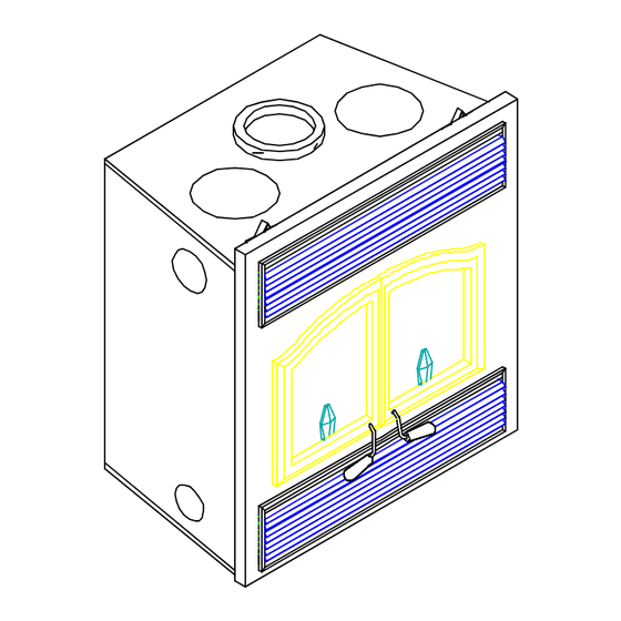
WARNING: The fireplace cannot be operated
without doors. Consult your dealer to select the
correct door model.
Listed to standards ULC-S610
UL-127
SECURITY CHIMNEYS INTERNATIONAL LTD
2125 Monterey St., Laval, Quebec, Canada, H7L 3T6
Tel.: (450) 973-9999
Printed in Canada
Rev. 04
Sept. 2002
PIBISULTRAEPA
Advertisement
Table of Contents

Related Manuals for Security Fireplace BIS ULTRA EPA


Summary of Contents for Security Fireplace BIS ULTRA EPA
-
Page 1: Installation Instructions
Installation Instructions This installation manual will help you obtain a safe, efficient, dependable installation for your fireplace and chimney system. Please read and understand these installation instructions before beginning your installation. E P A E P A CAUTION: Do not attempt to modify or alter the construction of the fireplace or its components. - Page 2 25 YEAR LIMITED WARRANTY Security Chimneys International Ltd. warrants to the original consumer-purchaser that the woodburning fireplace Model BIS ULTRA will be free from defects in material and workmanship, under normal use and service, for a period of twenty-five (25) years from the date of purchase. This warranty shall be void if the fireplace is not installed in accordance with the installation instruction manual provided with the product and does not cover damage caused by misuse of the product.
-
Page 3: Table Of Contents
TABLE OF CONTENTS Page SAFETY RULES .................................... 4 CERTIFICATION LABEL................................. 5 THE FIREPLACE INTRODUCTION................................6 Parts required ..................................6 Additional equipment (optional)............................ 6 OPERATING THE BIS ULTRA ............................. 7 Fuel..................................... 7 First fires .................................... 7 Building a fire ................................... 7 Combustion control................................. -
Page 4: Safety Rules
• Use only Security Fireplace glass doors, specifically designed for the model BIS ULTRA fireplace. • When cleaning the fireplace, the ashes should be placed in a metal container with a tight fitting lid. The closed container of ashes should be placed on a non-combustible floor or on the ground outside the house, pending final disposal. -
Page 5: Certification Label
CERTIFICATION LABEL... -
Page 6: The Fireplace
THE FIREPLACE INTRODUCTION The BIS ULTRA fireplace is an energy efficient, heat circulating, close combustion fireplace. You will receive a lifetime of comfort and enjoyment from your fireplace provided it is installed, maintained and operated properly. • Please read these instructions and retain this manual for future reference. •... -
Page 7: Operating The Bis Ultra
OPERATING THE BIS ULTRA Fuel The BIS ULTRA is designed to work best when fueled with seasoned cordwood. Hardwoods are preferred to softwoods since the energy content of wood is relative to its density. Hardwoods will result in a longer burning fire and less frequent refueling. A moisture content of 15% to 20% (seasoned) is recommended. -
Page 8: Combustion Control
Combustion control There is no flue damper in the BIS ULTRA. As is common with air tight stoves, the combustion air damper controls the air entering the firebox. This allows more precise control of the fire The combustion air damper knob is located below the left door. It is opened when moved completely to the left. -
Page 9: Medium Combustion
Medium combustion This is the recommended mode of operating the BIS ULTRA and should be the one normally used since it will deposit the least amount of creosote on the glass and in the chimney. The combustion air damper must be 3/4 closed. The precise setting will depend on many factors, including chimney length and the moisture content of the wood. -
Page 10: Smoking - Causes And Troubleshooting
Smoking – Causes and Troubleshooting To reduce the likelihood of smoking when opening the doors, set the damper to the "accelerated combustion" position before opening the doors. Your fireplace has been designed and tested to provide smoke free operation. Occasionally, there may be a small amount of smoking upon lighting the fire, until the chimney heats up but this should not continue. -
Page 11: Maintaining Your Bis Ultra Creosote
IMPORTANT NOTES 1. Do not block the hot air vents to the fireplace as this will cause the fireplace to overheat. 2. Never start a fire using gasoline, kerosene, charcoal lighter fluid or any other combustible liquid. 3. Do not burn coal. The sulphur in coal will corrode the firebox. 4. -
Page 12: Dealing With A Chimney Fire
6. Do not use the fireplace again until your chimney and fireplace have been inspected by a qualified chimney sweep or a Fire Department Inspector. Finish door casing care Use a glass cleaner and a soft cloth to polish the casing. Do not use abrasives such as steel wool or steel pads for they may scratch the casing’s finish. -
Page 13: Refractory Installation
Refractory replacement The intense heat of the fire will normally cause hairline cracks in the refractory. These cracks can be minimized by proper curing as described in "First fires". They will not normally diminish the effectiveness of the refractory. If large cracks develop, then the refractory should be replaced. To replace the refractory bricks, follow these steps: 1. -
Page 14: Doors Adjustment
Doors adjustment The doors may need to be adjusted to be completely airtight. The gaskets airtightness can be adjusted using the adjustment screw located on the fireplace façade at the bottom of the fireplace opening. (An Allen key # 1/8 will be necessary for adjustment). -
Page 15: Fireplace Installation
FIREPLACE INSTALLATION Locating the BIS ULTRA The best location for your fireplace is determined by considering the location of windows, doors, and the traffic flow in the room where the fireplace is located, allowing space in front of the unit for the hearth extension and the mantel, and taking into consideration the location of the hot air ducts (optional), outside air kit and chimney. -
Page 16: Framing, Facing And Mantel
Framing, facing and mantel The construction of the framing, facing, and mantel must be in accordance with the standards and the following illustrations (figures 7 to 11): 1. Frame the fireplace using 2" x 3" or heavier lumber. 2. WARNING: Combustible material cannot be used in the space directly above the fireplace. This area must remain empty for a height of 6'8"... - Page 17 INSULATED CHASE CONSTRUCTION Figure 11...
- Page 18 Facing Combustible material must be installed flush with the fireplace. It may not project in front of and on the fireplace (i.e. the steel façade of the fireplace) (figure 12). Non-combustible materials such as brick, stone or ceramic tile may project in front of and onto the fireplace facing (figure 13).
-
Page 19: Hot Air Ducting Installation
HOT AIR DUCTING INSTALLATION Different hot air ducting systems can be installed with the BIS ULTRA : - Gravity kit - Forced air kit - As is - Heat circulating Gravity kit Two kits are available : 2. Single hot air outlet including: (see Fig.14) 1. - Page 20 The single outlet system is designed to be installed either flush with the front of the BIS ULTRA or extended out slightly from the face of the fireplace (if installing with a brick or thick facing for example). To extend the double outlet system, it will be necessary to purchase two adjustable lengths (7B26ZL2A).
- Page 21 The duct system must be installed respecting the following : 1. Remove the plates closing up the 8" dia. holes on top of the fireplace. Then, cut the insulation in order to obtain two 8" dia. openings. Fix the adaptors on the fireplace openings by turning clockwise (figures 14 and 15).
-
Page 22: Central Forced Air Kit
Central forced air kit (Not EPA "Environmental Protection Agency" approved) The knock-outs provided on the back and on the sides of the BIS ULTRA allow the connection of insulated flexible pipe which enables you to heat adjacent rooms up to 50 feet from the fireplace. The ducting system must be installed as described below : 1. -
Page 23: Outside Air Kit
OUTSIDE AIR KIT During operation, the fireplace requires air for combustion and draws air out of the house. It may starve other fuel burning appliances such as gas or oil furnaces. As well, exhaust fans may compete for air, causing negative pressure in the house, resulting in smoke entering the house from the fireplace. -
Page 24: The Chimney
Installations, which are located on lower floors in the house, such as in a basement, in combination with outside chimney, are especially prone to flow reversal. The Security fireplace model BIS ULTRA is listed only with Security Chimneys International Ltd 6" dia. chimney systems. -
Page 25: Chimney Installation Instructions
CHIMNEY INSTALLATION INSTRUCTIONS 1. Cut and frame the holes in the ceiling, floor and roof where the chimney will pass (see figure 25). Use a plumb bob to line up the center of the holes. The sizes are indicated in table 1 for the floor and ceiling holes and table 2 (page 27) for the roof holes. - Page 26 (AIR COOLED GALVALUME CHIMNEY) NOTE THE OUTSIDE AIR KIT IS MANDATORY Figure 28...
- Page 27 AC CHIMNEY Figure 29 Figure 30 Table 2 ROOF DOWN SLOPE HOLE SIZE SLOPE ASHT+ / HT6103+ S-2100+ / HT6000+ Roff Pitch 6" 6" 6" 12 3/8" (314 mm) 14 1/8" (359 mm) 15" (380 mm) 2/12 12 9/16" (319 mm) 14 3/8"...
-
Page 28: Offset Chimney Installation
OFFSET CHIMNEY INSTALLATON The minimum chimney height when using elbows is : Fireplace model BIS ULTRA Chimney model ASHT+ / HT6103+ / S-2100+ / HT6000+ / AC Vertical installation 12 ft (3.66 m) Two (2) elbows 15 ft. (4.57 m) Four (4) elbows 17 ft. - Page 29 Table 4...
- Page 30 Figure 31 Figure 32...
-
Page 31: Angled Wall Radiation Shield
ANGLED WALL RADIATION SHIELD (RSM+, RSMI30, RSMI45) When traversing a combustible wall with the chimney at a 30º or 45º angle, an angled firestop or wall radiation shield must be installed. Only one is required. Note: 45º angle for Canada only In cold climate locations, we recommend that you use the insulated wall radiation shield since it will maintain the home’s thermal barrier. -
Page 32: Chimney Supports Installation
CHIMNEY SUPPORT INSTALLATION Universal roof support This support has three possible uses : For ASHT+/HT6103+ and S2100+/HT6000+, it must be used on a roof to support the chimney. It may be used on a floor, ceiling or roof above an offset to support the chimney above the offset. It may be used on a floor, ceiling or roof as a supplementary support when the chimney height exceeds 15 ft. -
Page 33: S2100+/Ht6000+ Chimney Adaptor
Figure 34 CHIMNEY ADAPTOR (S-2100+ / HT6000+) The fireplace is normally supplied with a chimney adaptor suitable for the ASHT+ / HT6103+ chimney. If you want to install a S-2100+ / HT6000+ chimney, an adaptor is available (6UCA) (figure 35). A separate starter section will also be required if AC chimney is installed. Figure 35... -
Page 34: Masonry Application
INSTALLATION INSTRUCTIONS FOR MASONRY APPLICATION WARNING: Before starting the installation, the masonry chimney must be inspected by a qualified sweep. The following requirements must be respected: The chimney must be absolutely clear of any soot residue or creosote. Check for cracks, loose or missing bricks that could inhibit correct installation of the liner. -
Page 35: Parts And Components
PARTS AND COMPONENTS LIST (AC Chimney) Description Part No. Lengths 6" dia. 12" length AC 6L12 18" length AC 6L18 36" length AC 6L36 48" length AC 6L48 15º elbow AC 6E15 30º elbow AC 6E30 Rain cap AC 6CPR Spark arrester cap AC 6CPE Supports... -
Page 36: Options
PARTS AND COMPONENTS LIST (Fireplace) Description: Part No. Victorian arch shape doors, gold plated 24K BAG38 Contemporary arch shape doors, gold plated 24K BCG38 Victorian arch shape doors, black BAN38 Contemporary arch shape doors, black BCN38 Outside air kit OPTIONS Gravity kit: Part No.: Complete double ducting system including : 2 elbows 90º, 2 telescopic... - Page 37 OPTIONS (Fireplace): Description: Part No. Cast-iron corner ornaments with magnets APPC-01 Cast iron corner ornaments with magnets APPCS-02 Cast-iron top ornament with magnet APP-03 Panel for clean face option BISCF Rigid firescreen BISZN-1 Heat activated on/off pre-wired fan kit UZY3 Masonry chimney adaptor BISUMA...
-
Page 38: Appendix (Specifications, Clearances, Replacement Parts)
APPENDIX SPECIFICATIONS Weight 412 lbs Height 40 ½". Width 38" Depth 24 1/2" Chimney weight ASHT+ (6" dia.) : 6.25 lb/ft. Chimney weight S2100+ (6" dia.) : 10.8 lb/ft. CLEARANCE TO COMBUSTIBLES The following clearances meet the minimum requirements for a safe installation Side wall: 24"...
Need help?
Do you have a question about the BIS ULTRA EPA and is the answer not in the manual?
Questions and answers