Table of Contents
Advertisement
Quick Links
Product Information
Product Model:
Product Name:
Manufacturer Name:
After Service Contact Information:
Address: No.2 Innovation First Road, Technical Innovation Coast,
Fax: +86-756-3399919
Post code: 519085
Toll-free consultation hot line: +86-400-8818-233
Revision History
This manual has a revision number. This revision number changes
whenever the manual is updated due to software or technical specification
change. Contents of this manual are subject to change without prior notice.
Document No.: J/A8CE-A-010
Revision number: V5.3
Release time: Apr. 2014
Copyright © 2014 Guangdong Biolight Meditech Co., Ltd. All rights
reserved.
CE mark
EC Representative Name:
Shanghai International Trading Corp. GmbH (Hamburg)
EC Representative Address:
Eiffestrasse 80, 20537 Hamburg Germany
AnyView A8/A6/A5/A3
Patient monitor
Guangdong Biolight Meditech Co.,Ltd.
Hi-tech Zone, Zhuhai, P.R. China
I
Advertisement
Table of Contents

Summary of Contents for Anyview A6
-
Page 1: Product Information
Product Information Product Model: AnyView A8/A6/A5/A3 Product Name: Patient monitor Manufacturer Name: Guangdong Biolight Meditech Co.,Ltd. After Service Contact Information: Address: No.2 Innovation First Road, Technical Innovation Coast, Hi-tech Zone, Zhuhai, P.R. China Fax: +86-756-3399919 Post code: 519085... -
Page 2: About This Manual
Statement Manufacturer holds the copyright of this manual, and we are also entitled to deal with this manual as confidential files. This manual is only used for operation, maintenance and service of product, someone else can not publish the manual. This manual contains exclusive information protected by copyright laws and we reserve its copyright. - Page 3 The manual is geared for clinical professionals who are expected to have a working knowledge of medical procedures, practiced and terminology as required for monitoring patients. All illustrations in this manual serve as examples only. They may not necessarily reflect the setup or data displayed on your product. Conventions: ...
-
Page 4: Table Of Contents
Contents Chapter 1 General Introduction..................1 1.1 Intended Use........................1 1.2 Main Unit......................... 1 1.3 Measurement Modules....................14 1.4 Equipment Symbols.....................17 Chapter 2 Safety........................18 2.1 Safety Information......................1 2.2 General Safety.........................3 2.3 Important Notes for Safety...................5 2.4 Safe Operation Conditions................... 7 Chapter 3 Basic Operations....................7 3.1 Unpacking and Checking....................1 3.2 Getting Started........................ - Page 5 Chapter 5 Alarm........................11 5.1 Alarm Category.......................1 5.2 Alarm Level........................1 5.3 Alarm Indicators......................2 5.4 Alarm Status Symbol..................... 4 5.5 Setting Alarm Volume....................4 5.6 Parameter Alarm......................4 5.7 Silence..........................6 5.8 Pausing Alarms....................... 6 5.9 Acknowledging Alarms....................7 5.10 Latching Alarms......................7 5.11 When an Alarm Occurs....................
- Page 6 8.4 Resp Display........................2 8.5 Setting Resp........................3 Chapter 9 SpO2........................3 9.1 Introduction........................1 9.2 Safety Information......................1 9.3 Monitoring Procedure....................4 9.4 SpO Display........................4 9.5 Setting SpO ........................6 9.6 Measurement Limitations..................... 9 9.7 Masimo Information....................10 9.8 Nellcor Information..................... 11 Chapter 10 Temperature (Temp)..................11 10.1 Introduction........................1 10.2 Safety Information.......................
- Page 7 12.5 Setting IBP........................3 12.6 Calculating Cerebral Perfusion Pressure..............4 12.7 Zeroing the Pressure Transducer................4 12.8 Pressure Calibration....................5 Chapter 13 Carbon Dioxide (CO2)..................5 13.1 Introduction........................1 13.2 Monitoring Procedure....................1 13.3 CO Display........................6 13.4 Setting CO2........................6 13.5 Zeroing........................... 8 13.6 Calibration........................9 13.7 Removing Exhaust Gases from the System............
- Page 8 Chapter 16 C.O........................7 16.1 Overview........................7 16.2 Safety Information....................... 1 16.3 C.O. Display........................1 16.4 Measurement of C.O....................2 16.5 C.O. Setting........................3 16.6 Measurement Restrictions..................7 16.7 Influencing Factors...................... 7 Chapter 17 CSM........................7 17.1 Introduction........................7 17.2 Safety Information....................... 1 17.3 Monitoring Procedure....................2 17.4 CSM Display.........................4 17.5 Setting CSM........................
- Page 9 20.2 Reviewing Waveform....................1 20.3 Releasing Freezing.......................2 Chapter 21 Reviewing......................2 21.1 Reviewing Graphic Trends..................1 21.2 Reviewing Tabular Trends..................2 21.3 Reviewing NIBP Measurement Results..............3 21.4 Reviewing Parameter Alarm..................4 21.5 Reviewing Holographic Waveform................5 Chapter 22 Calculations....................... 6 22.1 Drug Dose Calculation....................1 22.2 Hemodynamic Calculation..................
- Page 10 25.4 Checking Battery Performance................. 2 25.5 Disposing Batteries......................3 Chapter 26 Maintenance and Cleaning................3 26.1 Equipment Maintenance..................... 1 26.2 Equipment Cleaning....................2 26.2 Cleaning of the Monitor..................... 2 26.3 Cleaning of EMS......................3 26.4 Cleaning and Sterilizing of Accessories..............3 Chapter 27 Accessories......................6 Appendix A Product Specifications...................
-
Page 11: Chapter 1 General Introduction
Patient monitor User’s manual Chapter 1 General Introduction 1.1 Intended Use The monitor is intended to be used for monitoring, displaying, reviewing, storing and alarming of multiple physiological parameters of adult, pediatric and neonatal, including ECG, ST segment analysis, arrhythmia analysis, Heart Rate (HR), Respiration Rate (RR), Temperature(Temp), Pulse Oxygen Saturation(SpO ), Pulse... -
Page 12: Main Unit
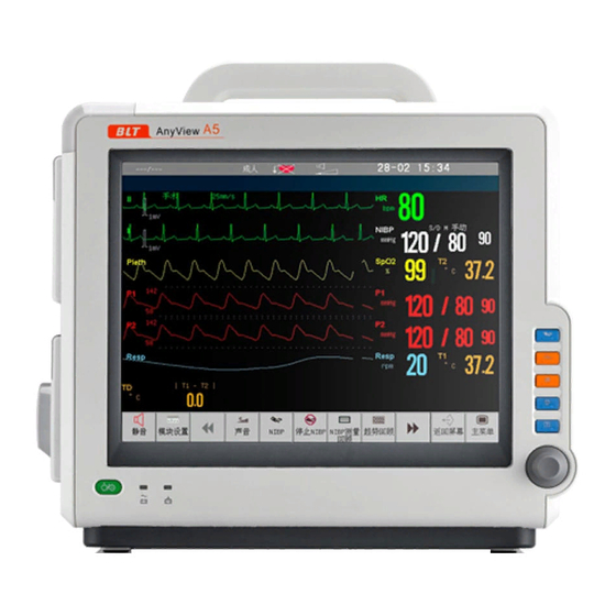
Patient monitor User’s manual 1.2 Main Unit 1.2.1 Front View AnyView A8 Patient monitor 4 5 6 AnyView A6 Patient monitor Chapter 1-2... - Page 13 Patient monitor User’s manual AnyView A5 Patient monitor AnyView A3 Patient monitor Chapter 1-3...
- Page 14 Patient monitor User’s manual 1. Physiological alarm indicating lamp When a physiological alarm occurs, this lamp will light up as defined below: High level alarm: the lamp quickly flashes red. Medium level alarm: the lamp slowly flashes yellow. ...
-
Page 15: Side View
Press this button to acknowledge all active alarms. This switches off the audible alarm indicators and alarm lamps. (Details refer to Alarm chapter) Press this button to start or stop NIBP measurement. 1.2.2 Side View AnyView A8 Patient monitor Left side: Right side: Chapter 1-5... - Page 16 Patient monitor User’s manual AnyView A6 Patient monitor Left side: Right side: AnyView A5 Patient monitor Left side: Right side: Chapter 1-6...
- Page 17 Patient monitor User’s manual AnyView A3 Patient monitor Left side: Right side: 1. EMS slot 2. Other plug-in module slots 3. Contact point 4. SD Memory card slot 5. Recorder 6. Handle Caution: In order to prevent poor contact due to dust accumulated, please regularly clean the contact point according to actual application condition.
- Page 18 Patient monitor User’s manual 1.2.3 Bottom View AnyView A8 Patient monitor AnyView A6 Patient monitor Chapter 1-8...
- Page 19 Patient monitor User’s manual AnyView A5 Patient monitor AnyView A3 Patient monitor 1. Battery compartment Chapter 1-9...
-
Page 20: Rear View
Patient monitor User’s manual 1.2.4 Rear View AnyView A8 Patient monitor Chapter 1-10... - Page 21 Patient monitor User’s manual AnyView A6 Patient monitor Chapter 1-11...
- Page 22 Patient monitor User’s manual AnyView A5 Patient monitor Chapter 1-12...
- Page 23 If the protective earth system is damaged, the equipotential grounding system can take on the safety function of protective earth conductor. 3. DVI display connector (AnyView A5 and AnyView A3 don’t have the connector) Connect to standard DVI display for secondary displaying.
- Page 24 8. USB socket onnect to USB device, such as keyboard and mouse. 9. Auxiliary plug-in box connector (AnyView A3 doesn’t have the connector) Connect to auxiliary plug-in box. 10. DC12V power input connector (Only AnyView A3 has the connector) Warning: ...
-
Page 25: Measurement Modules
Patient monitor User’s manual 1.3 Measurement Modules The monitor can support the following modules: EMS: Emergency Mobile Server, it is a multifunction measurement module with LCD, it can simultaneously monitor ECG, Resp, SpO , PR, Temp, NIBP, IBP. MPS: Multi-parameters Server, it is a Multi-parameters measurement ... - Page 26 Patient monitor User’s manual EMS/MPS and remove it. —— After plugging in EMS/MPS, please make sure whether the indicating lamp on EMS/MPS lights up. If not, please pull out and plug in EMS/MPS once more. Plug in and pull out of other modules ...
-
Page 27: Equipment Symbols
Patient monitor User’s manual Note: EMS can connect with the host monitor as the multi-function measuring module of the host monitor. At the time, among the buttons of EMS, the screen switching button is still enabled, the rest functional buttons are equal to the corresponding buttons on the host monitor. - Page 28 Patient monitor User’s manual Symbol Symbol Note Symbol Symbol Note CE mark Short for “Bispectral Index” Auxiliary plug-in box Network connector connector Manufacture date Manufacturer Degree of protection against IPX1 Serial number ingress of liquid Batch code Catalog number Use by date Do not re-use [YYYY-MM-DD] Temperature limitation...
-
Page 29: Chapter 2 Safety
Patient monitor User’s manual Chapter 2 Safety 2.1 Safety Information Warning: Before putting the system into operation, verify that the monitor, connecting cables and accessories are in correct working order and operating condition. Please connect the monitor to a socket with protective earth. If the socket does not have protective earth conductor, please do not use the socket and use battery to provide power to the monitor. - Page 30 Patient monitor User’s manual Caution: To ensure patient safety, use only parts and accessories specified in this manual. At the end of its service life, the monitor, as well as its accessories, must be disposed of in compliance with the guidelines regulating the disposal of such products.
-
Page 31: General Safety
Patient monitor User’s manual Note: Put the monitor in a location where you can easily see the screen and access the operating controls. Keep this manual in the vicinity of the monitor so that it can be obtained conveniently when needed. - Page 32 Patient monitor User’s manual The unit displaying this symbol contains an F-Type isolated (floating) applied part providing a high degree of protection against shock, and is defibrillator-proof. Type CF applied part, defibrillation protected The unit displaying this symbol contains an F-Type isolated (floating) applied part providing a high degree of protection against shock, and is defibrillator-proof.
-
Page 33: Important Notes For Safety
Patient monitor User’s manual 7. To guarantee the normal and safe operation of the monitor, a preventive check and maintenance should be conducted for the monitor and its parts every 6-12 months (including performance check and safety check) to verify the instrument can work in a safe and proper condition and it is safe to the medical personnel and the patient and has met the accuracy required by clinical use. - Page 34 Patient monitor User’s manual Before Use Before putting the system into operation, please visually inspect all connecting cables for signs of damage. Damaged cables and connectors must be replaced immediately. Before using the system, the operator must verify that it is in correct working order and operating condition.
-
Page 35: Safe Operation Conditions
Patient monitor User’s manual performance of the device. For this reason, make sure that all external devices operated in the vicinity of the monitor comply with the relevant EMC requirements. X-ray equipment or MRI devices are a possible source of interference as they may emit higher levels of electromagnetic radiation. -
Page 36: Chapter 3 Basic Operations
Patient monitor User’s manual Chapter 3 Basic Operations 3.1 Unpacking and Checking 1. Unpacking Before unpacking, examine the packing case carefully for signs of damage. If any damage is detected, contact the carrier. If the packing case is intact, open the package. 2. -
Page 37: Getting Started
Patient monitor User’s manual leading to damage of equipment and other unexpected results. 3.2 Getting Started 3.2.1 Inspecting the Monitor 1. Before you start to make measurements, carry out the following checks on the monitor including all connected modules. ——Check for any mechanical damage; ——Check for any incorrect connection of all the external cables and accessories. -
Page 38: Starting Monitoring
Patient monitor User’s manual 3.3 Starting Monitoring 1. Decide what parameters should be monitored or measured. 2. Install required modules or sensors. 3. Check whether the installation of modules or sensors is correct. 4. Check whether all kinds of settings are correct. 5. -
Page 39: Networked Monitoring
Patient monitor User’s manual 3.6 Networked Monitoring If the user intends to connect the monitor to the central monitoring system, plug its connecting electrical cable into the network connector at the back of the monitor or use Wifi. When the central monitoring system is connected through Wifi, make sure that the network line interface of the Wifi module is well connected to the network interface of the host machine of the monitor. -
Page 40: Screen Display
Patient monitor User’s manual 3.8 Screen Display The monitor adopts a display screen of high-resolution TFT LCD. Measurement numerics, waveforms, patient information, alarm area and menu can be displayed on the screen. Standard screen is shown as follows: 1. Patient info area Shows the room number, bed number, patient name, patient category and paced status of patient. -
Page 41: Using The Smartkeys
An area where any parameter stays is the smartkey; you may select a parameter area to enter a setting menu of the corresponding parameter. Touch smartkeys (Only for AnyView A8 patient monitor) Touch smartkeys at the bottom of the screen may be configured, through which some functions may be quickly executed. - Page 42 1. Select 【 Main menu】 smartkey→ 【Smartkey Define】, select the smartkeys you want to display on the screen, and you also can arrange the smartkeys as you like . 2. For AnyView A8,A6: Select【Back】to confirm it. The symbols on the smartkeys are shown as follows: Smartkey Smartkey Note...
-
Page 43: Setting Measurement Modules
Patient monitor User’s manual 3.10 Setting Measurement Modules 3.10.1 Setting Measurement Modules Select【Module Set】smartkey to enter the module config window, shown as follows. Depending on different configuration, your monitor will display different contents. EMS and other parameter measurement modules which are configured by user are displayed in above window, and label displays near the corresponding connector of module. - Page 44 Patient monitor User’s manual Changing Temp Label 1. Select 【 Module Set 】 smartkey to enter the Module config window in which you can select the Temp label you want to alter. Then, there is a module config window popping up. 2.
-
Page 45: Using Mouse
Patient monitor User’s manual with a Temp module (module A), and the module uses the label Tskin, then if you plug in another Temp module (module B) with the label Tskin, thus the monitor will close the module B automatically. To resolve conflict of labels: ——... -
Page 46: Using Soft Keyboard
Patient monitor User’s manual 3.12 Using Soft Keyboard The software of the monitor can provide soft keyboard to input data and support entering in Chinese and English. 3.13 Using SD Memory Card In order to avoid patient’s data loss as the power of a monitor suddenly fails, the monitor can be fitted with SD memory card that can provide the data saving function while power failure or power off. -
Page 47: General Setting
Patient monitor User’s manual has been turned on. Within the short time after starting monitor, data probably cannot be stored in a SD memory card. Please do not use the SD memory card in any equipment other than the monitor. - Page 48 Patient monitor User’s manual system time before implementing monitoring. If the configuration is to be conducted during the process of monitoring, the user is advised to switch off the monitor after exiting the current window and then restart it. The time for the revision takes effect after the current window is exited.
- Page 49 Patient monitor User’s manual save the changed settings as user configuration. The monitor can save many user configurations, which can be self-defined in customized names by user. At first, the setting of the monitor should be adjusted in line with requirement to ensure that the monitor’s settings are suitable for the monitored patient.
-
Page 50: Chapter 4 User Interface
Patient monitor User’s manual Chapter 4 User Interface 4.1 Display Style Display style of user interface can be set according to your need. Including: ——Defined the screen layout, setup the parameter and wave to be displayed; ——Manage the screen layout; ——Display the alarm limit;... -
Page 51: Main Screen Select
Patient monitor User’s manual 2. Select 【Parameter Color Setup 】 , click the color block of corresponding parameter, and then select the color according to your need from the popped menu. 4.1.5 Sweep Mode 1. Select【Main Menu】smartkey→【Screen Setup】; 2. Set【Sweep Mode】to【Refresh】or【Scroll】 : 【Refresh】:The waveform is still, refreshing from left to right. - Page 52 Patient monitor User’s manual Standard Screen To enter standard screen: Select 【 Main Menu 】 smartkey→ 【 Main Screen Select 】 → 【Standard】. Or select【Main Screen】smartkey→【Standard】. Chapter 4-3...
- Page 53 Patient monitor User’s manual 7-lead To enter 7-lead screen: Select【Main Menu】smartkey→【Main Screen Select】→ 【7-lead】 . Or select【Main Screen】smartkey→【7-lead】. The ECG waveforms of 7-lead are displayed in the waveform display area, they are I, II, III, aVR, aVL, aVF, and V- respectively. Chapter 4-4...
- Page 54 Patient monitor User’s manual 12-lead To enter 12-lead screen: Select 【 Main Menu】 smartkey→ 【Main Screen Select】 → 【12-lead】 . Or select【Main Screen】smartkey→【12-lead】. The 12-lead ECG waveforms are displayed in the waveform display area, they are I, II, Ⅲ, aVR, aVL, aVF, V1, V2, V3, V4, V5 and V6. Chapter 4-5...
- Page 55 Patient monitor User’s manual Big Numerics To enter big numerics screen: Select 【 Main Menu 】 smartkey→ 【 Main Screen Select 】 →【 Big Numerics】. Or select【Main Screen】smartkey→【Big Numerics】. On big numerics screen, you can select any parameters on screen, conduct some parameter settings and observe the parameter as required.
- Page 56 Patient monitor User’s manual HI RES Trend To enter high resolution trend screen: Select【Main Menu】smartkey→【Main Screen Select】→【HI RES Trend】. Or select【Main Screen】smartkey→【HI RES Trend】. HI RES Trend The HI RES Trend graph relevant to the parameters is displayed on the left corner of the waveform, it shows the graphic trend for some time of each parameter.
- Page 57 Patient monitor User’s manual OxyCRG To enter OxyCRG screen: Select 【Main Menu】 smartkey→ 【Main Screen Select】 → 【OxyCRG】 . Or select【Main Screen】smartkey→【OxyCRG】. The graphic trend of HR, SpO and Resp within 16 minutes are displayed under the waveforms. Chapter 4-8...
- Page 58 Patient monitor User’s manual NIBP Review Screen To enter NIBP review screen: Select【Main Menu】smartkey→【Main Screen Select】→【NIBP Review】. Or select【Main Screen】smartkey→【NIBP Review】. The recent groups of NIBP measurement results are displayed below the waveforms. Chapter 4-9...
- Page 59 Patient monitor User’s manual Other Bed screen To enter other bed screen: Select【Main Menu】smartkey→【Main Screen Select】→【Other Bed】. Or select【Main Screen】smartkey→【Other Bed】. After your monitor is connected to the central monitoring system, you can realize other bed monitoring by selecting the monitors for other beds in the same network.
- Page 60 Patient monitor User’s manual 1) Select the Other-Bed-Monitoring window, and then choose the device number you need in the ejected list; 2) Select【Select Wave】to display a certain physiological parameter waveform of the selected other-bed monitor in the other-bed-monitoring window; 3) Lastly, select 【 Start/Stop】 to receive data and start other-bed monitoring. If need to stop other-bed monitoring, select【...
-
Page 61: Chapter 5 Alarm
Patient monitor User’s manual Chapter 5 Alarm Alarm refers to a prompt that is given by the monitor for medical personnel through visual, audible and other means when a vital sign appears abnormal or the monitor occurs technical problem. Note: The monitor generates all the audible and visual alarms through ... -
Page 62: Alarm Indicators
Patient monitor User’s manual High level alarms: Indicate that the patient is in a life threatening situation and an emergency treatment is necessary. This is the highest level alarm. Medium level alarms: Indicate that the patient’s vital signs appear abnormal and an immediate treatment is required. -
Page 63: Alarm Lamp
Patient monitor User’s manual 5.3.2 Alarm Lamp When a physiological alarm occurs, the alarm levels are indicated in the following different visual ways: Alarm level Visual prompt High Alarm lamp flashes in red with 2 Hz. Medium Alarm lamp flashes in yellow with 0.5 Hz. Alarm lamp lights on in yellow without flashing. -
Page 64: Alarm Status Symbol
Patient monitor User’s manual Technical alarm 1) Technical alarm messages are displayed in the technical alarm area. 2)The “*” symbol before the alarm message match the alarm level as follows: Medium level alarms: ** Low level alarms: * 3)The background color for the alarm message is blue. ... - Page 65 Patient monitor User’s manual alarm setting of parameter is independent from each other. Or you can select 【Main Menu】smartkey→【Alm Setup】to set the parameter alarm. For the parameters whose alarm switch is set to ON, the alarm will be triggered when at least one of them exceeds alarm limit. The following actions take place: 1.
-
Page 66: Silence
Patient monitor User’s manual Warning: Medical personnel should set the alarm limits of parameters in line with the clinical environment and existing clinical experience. Before monitoring, please confirm whether the alarm setting is suitable for the monitored patient. 5.7 Silence Select 【... -
Page 67: Acknowledging Alarms
Patient monitor User’s manual dependent on whether the alarm condition is met. But when pressing the button , the alarm of lead-off/sensor-off will automatically turn into a prompt message. 5.9 Acknowledging Alarms Press the button on the front panel of the monitor; you can acknowledge all active physiological and technical alarms: ——The visual alarm and audible alarm are all shut off. - Page 68 Patient monitor User’s manual 1. Check the patient’s condition. 2. Identify alarming parameter and alarm category. 3. Identify the cause of the alarm. 4. Silence the alarm, if necessary. 5. When cause of alarm has been over, check that the alarm system is working properly.
-
Page 69: Chapter 6 Patient Management
Patient monitor User’s manual Chapter 6 Patient Management 6.1 Admitting a Patient The monitor displays physiological data and stores it in the trends as soon as a patient is connected. This lets you monitor a patient who is not yet admitted. However, it is very important to admit patients properly. -
Page 70: Quick Admitting A Patient
Patient monitor User’s manual ——Remarks: User can enter some more patients’ information, such as history of genetic disease. 3. Select【OK】, the patient status changes to admitted. Warning: 【Patient Type】and【Paced】status will always contain a default value, regardless of whether the patient is admitted or not. Users must confirm whether the default value is suitable for the monitored patient. -
Page 71: Discharging A Patient
Patient monitor User’s manual 6.4 Discharging a Patient You should always perform a discharge before starting monitoring for a new patient, even if your previous patient was not admitted. To discharge a patient, 1. Select【Patient Manage.】smartkey→【Discharge Pat.】. 2. In the popped up menu, you can: ——Do not choose【Standby】, and select【OK】, then the monitor will enter the【Pat. - Page 72 Patient monitor User’s manual with your current patient’s data. 2. Moving the patient using EMS as the transport monitor. 3. At the new monitoring location, connect the EMS to the new host monitor. 4. After that, an asking window will be popped up on the new host monitor’s screen.
- Page 73 Patient monitor User’s manual 2. If Neither Patient Data Set is Correct Select【 New Patient】in the asking window, if you are sure that none of the information is correct. This discharges all patients, erases all data in both the monitor and EMS, resets all settings to the default setting, and lets you admit a new patient.
-
Page 74: Chapter 7 Ecg
Patient monitor User’s manual Chapter 7 ECG 7.1 Introduction Before mechanical systole, the heart firstly produces electrical excitement, which results in biological current, and conducts the current to the body surface through tissue and humour. Different potential changes take place at various parts of the body, thus body-surface potential differences are formed. -
Page 75: Monitoring Procedure
Patient monitor User’s manual electrodes or relocate the electrodes in case of skin allergy occurs. When conducting defibrillation, it is imperative to only use the ECG electrodes and cables specified by manufacturer. Do not touch the patient, bed or the monitor during defibrillation. ... - Page 76 Patient monitor User’s manual 7.3.2 Placing Electrode 1. Preparation before electrode placement 1) Skin preparation (refers to Chapter 7.3.1); 2) Check if the buttons on the electrodes are clean and free of damage; 3) Place the electrodes on the body of patient. Before attaching, smear some conducting cream on the electrodes if the electrodes are not electrolyte self-supplied;...
- Page 77 Patient monitor User’s manual 2. Electrode Placement 3-Lead Take the AHA standard as an example, when conducting 3-lead ECG monitoring, use 3-lead ECG cable. The three limb-leads of RA, LA and LL as shown in below figure, will be placed on the relevant locations. This connection can establish the lead of I, II, III.
- Page 78 Patient monitor User’s manual 12-Lead Take the AHA standard as an example, when conducting 12-lead ECG monitoring, use 12-lead ECG cable, and all the leads are placed on the relevant locations respectively as shown in the below figure. This kind of connection realizes the establishment of such 12 leads as I, II, III, aVR, aVL, aVF, V ...
- Page 79 Patient monitor User’s manual When using the ESU device, avoid placing the electrodes near the ESU grounding pad, otherwise, grate deal interference will influence the ECG signals. The monitor should be placed far from the operating table. Power wires and the ECG cables should be partitioned and should not be in parallel.
-
Page 80: Ecg Display
Patient monitor User’s manual 1. Select ECG parameter area, enter ECG parameter setup menu, select【Lead Type】. 2. You can select【3 lead】,【5 lead】or【12 lead】. 7.3.5 Checking Paced Status It is important to set the paced status correctly when you start monitoring ECG. -
Page 81: Setting Ecg
Patient monitor User’s manual If the【Paced】status has been set to【Yes】and the system detects paced signal, the paced pulse “ ” will be marked on the ECG wave. ( As it shown ︱ above) Parameter Display HR value Heartbeat icon HR unit HR alarm limit If the monitor doesn’t obtain an effective HR value by ECG measuring,... -
Page 82: St Monitoring
Patient monitor User’s manual Note:Under the mode of 【 Surgery】and【 Monitor】 ,the state of the filter cannot be regulated. Only under the state 【 Diagnosis 】 of 【 User 】 can the state be regulated. Please select 【 Monitor 】 during monitoring a patient, select【Surgery】under the state of great interference. - Page 83 Patient monitor User’s manual Warning: Some clinical conditions may make it difficult to achieve reliable ST monitoring, for example: If you are unable to get a lead that is not noisy; —— If the patient is continuously ventricularly paced; ——...
- Page 84 Patient monitor User’s manual 7.6.4 Adjust ST point The ST value for each beat complex is the vertical difference between the ISO point and the ST point, as shown in the figure below. The isoelectric (ISO) point provides the baseline, the ST point is at the midpoint of the ST segment. In the ST analysis menu, select 【...
- Page 85 Patient monitor User’s manual 7.6.5.1 ST Map Display The monitor can derive a multi-axis portrait from the ST analysis (each axis represents a lead), It displays two planes obtained from a multilead ECG in a multi-axis diagram.As the following diagram. In the diagram, each axis represents a limb lead, or a chest lead.The positive value (+) of each axis with the name of relate lead.
-
Page 86: Arrhythmia Monitoring
Patient monitor User’s manual 3. The ST Map will refresh at each 12s intervals. The ST values of each axis will refresh like that. 4. Change the radius of a circle of of the ST map (that is the scale) The value which the radius of a circle reflects can be changed, the options are 1, 2, 3, 5, 10 and 15.When the value of the radius changed, the ST map area changed follows.The values bigger, the areas smaller. - Page 87 Patient monitor User’s manual 7.7.3 Setting Arrhythmia Alarm Select【ARR Analysis】→【ARR Alm Setup】in the ECG setting menu, in the popped up menu, you can set the alarm status for each Arrhythmia, including alarm switch, alarm level and alarm print switch. You can select 【ALL ARR Alm-Resume Default】,【All ARR Alm-Alm Switch】,【ALL ARR Alm-Alm Level】and【All ARR Alm-Alm Print】to set the alarm status for all arrhythmia.
- Page 88 Patient monitor User’s manual Initiating Arrhythmia Relearning Manually During monitoring, if you have any question on the analysis result of arrhythmia, you can start the arrhythmia relearning manually. Select 【 ARR Analysis 】in the ECG setting menu, and select【 Arr. Relearning 】 . Then, a prompt message of “ARR is relearning”...
-
Page 89: Qt/Qtc Interval Monitoring
Patient monitor User’s manual In the above window, you can: — — In the area of smartkeys which is under the the ARR Wave window, you can select 【 Record 】 to record the current displaying ARR waveform and parameter values. —... - Page 90 Patient monitor User’s manual QT interva The QT interval has a close relationship to heart rate. Faster heart rate shorten the QT interval; Conversely, the QT interval will prolonged. 7.8.2 QTc Interval QTc interval is that the QT interval after corrected of heart rate, is the functionary index of the heart depolarization and the rapolarization.The monitor use the Bazett formula for correction.
- Page 91 Patient monitor User’s manual 7.8.4 Switching QT Monitoring On and Off Select the 【QT Anal Setup 】 in the ECG parameter setting menu, then select【QT Anal. Switch】, you can set it to【On】or【Off】. 7.8.5 Setting QT Base Line In order to quantify changes in the QTc value, you can set a QTc baseline. The baseline can be used to calculate the value of DQTc.
-
Page 92: Chapter 8 Respiration Rate (Resp)
Patient monitor User’s manual Chapter 8 Respiration Rate (Resp) 8.1 Introduction For the respiratory measurement (Resp), the monitor measures the thoracic impedance between two ECG electrodes on the patient’s chest. Changes in the impedance due to thoracic movement produce the Resp waveform on the monitor screen. -
Page 93: Resp Display
Patient monitor User’s manual Caution: In order to get the best Resp waveforms, when using RA and LA electrodes for measuring Resp, it is advised to place them horizontally; when using RA and LL electrodes, it is advised to place them cornerways. ... -
Page 94: Setting Resp
Patient monitor User’s manual Parameter Display RR unit RR value alarm limit 8.5 Setting Resp 8.5.1 Setting Resp Parameter Select Resp parameter area to enter Resp parameter setting menu. Setting Resp Lead In the Resp setting menu, select 【 Resp Lead】 , and you can select 【 RA-LL】 or【RA-LA】. -
Page 95: Chapter 9 Spo2
Patient monitor User’s manual Chapter 9 SpO2 9.1 Introduction The measurement of oxygen saturation of arterial blood (also known as pulse oxygen saturation, usually shortened as SpO ) adopts the principles of light spectra and volume tracing. The LED emits lights with two specific wavelengths, which are selectively absorbed by oxygenated hemoglobin and deoxyhemoglobin. - Page 96 Patient monitor User’s manual Check the SpO2 sensor and its package for any sign of damage before use. Do not use the sensor if any damage is detected. Before use, the operator must ensure the compatibilityies of the monitor, SpO sensor and extension cables;...
- Page 97 Patient monitor User’s manual patient in a bed with arm dangling to the floor). Venous pulsations may cause erroneous low readings (e.g. tricuspid value regurgitation). The pulsations from intra-aortic balloon support can be additive to the pulse rate on the oximeter pulse rate display. ...
-
Page 98: Spo Display
Patient monitor User’s manual The pleth wave is not equal to the intensity of PR signal. The production divergence and drive current of LED influence the range of the peak wavelength of the emitted light by the oxygen probe. ... - Page 99 Patient monitor User’s manual 9.4.2 Parameter Display For BLT SpO and Nellcor SpO Signal intensity indicator unit value Pleth bar Description Indicator of signal intensity “Weak Signal” The signal strength is too weak to measure. “*” The signal strength is low. “**”...
- Page 100 Patient monitor User’s manual 1. SpO value; 2. SpO unit; 3. SpMet (Methemoglobin Saturation) value and unit; 4. PVI (Pleth Variability Index) value and unit; 5. SpHb (Total Hemoglobin) value and unit; 6. SpOC (Oxygen Content) value and unit; 7. PI (Perfusion Index) value and unit; 8.
-
Page 101: Setting Spo
Patient monitor User’s manual 9.5 Setting SpO 9.5.1 Setting SpO Parameter Select SpO parameter area to enter SpO parameter setting. Setting NIBP measurement on the same limb When NIBP and SpO are simultaneously measured to the same limb of patient, the operator shall enter the SpO parameter setting menu and set 【NIBP Same Side】... - Page 102 Patient monitor User’s manual then select【PR Source】. The options of【SpO 】 , 【ART】and【Auto】are available. 【ART】: The monitor takes ART as the PR source. 【SpO2】: The monitor takes SpO as the PR source. 【 Auto 】 : When the monitor can detect ART signal, the monitor will automatically take the ART as the PR source.
-
Page 103: Measurement Limitations
Patient monitor User’s manual Setting SmartTone 【SmartTone】is a feature that affects pulse beep and can be selected in the SpO parameter setting menu. When you set it to【On】, it will allow the audible pulse beep to beep when the pleth shows signs of motion. The pulse beep is suppressed during signs of motion when SmartTone is set to【Off】. - Page 104 Patient monitor User’s manual then check the monitor and SpO sensor. The following factors may influence the accuracy of measurements: ——Incorrect sensor application or use; ——Significant levels dysfunctional hemoglobins. (such carboxyhemoglobin or methemoglobin); ——Intravascular dyes such as indocyanine green or methylene blue; ——Exposure to excessive illumination, such as surgical lamps (especially ones with a xenon light source), bilirubin lamps, fluorescent lights, infrared heating lamps, or direct sunlight (exposure to excessive...
-
Page 105: Masimo Information
Patient monitor User’s manual 9.7 Masimo Information Masimo Patents: This device is covered under one or more of the following U.S.A. patents: 5,758,644, 5,823,950, 6,011,986, 6,157,850, 6,263,222, 6,501,975 and other applicable patents listed at: www.masimo.com/patents.htm. No Implied License: Possession or purchase of this device does not convey any express or implied license to use the device with unauthorized sensors or cables which would, alone, or in combination with this device, fall within the scope of one... -
Page 106: Chapter 10 Temperature (Temp)
Patient monitor User’s manual Chapter 10 Temperature (Temp) 10.1 Introduction The monitor measures Temperature with Temperature sensors. The monitor has maximum eight channels for Temp measurement option, and can display the temperature of eight channels and temperature difference (TD) at the same time. 10.2 Safety Information ... -
Page 107: Monitoring Procedure
Patient monitor User’s manual Note: If Temp to be measured beyond probe’s measuring range, over measuring range alarm will be displayed on the screen. Check if probe is on the corresponding patient body site, or change it to other site on the patient. -
Page 108: Temp Display
Patient monitor User’s manual 10.4 Temp Display The monitor can display Temp of each channel (such as T1 and T2) and the Temp difference between two channels (TD). Temp Label Temp unit Temp unit Temp Difference Temp value between 2 channels 10.5 Setting TD ... -
Page 109: Chapter 11 Nibp
Patient monitor User’s manual Chapter 11 NIBP 11.1 Introduction The monitor uses the oscillometric method for measuring NIBP. It is applicable for adult, pediatric and neonatal patients. The method of oscillometric indirectly estimates the systolic and diastolic pressures within the blood vessels by measuring the change of the pressure within blood pressure cuff along with the volume of the arteries and calculates the average pressure. -
Page 110: Measurement Limitations
Patient monitor User’s manual 11.3 Measurement Limitations NIBP measurements are impossible with heart rate extremes of less than 40 bpm or greater than 240 bpm, or if the patient is on a heart-lung machine. The measurement may be inaccurate or impossible: ——with excessive and continuous patient movement such as shivering or convulsions;... - Page 111 Patient monitor User’s manual Confirm the cuff has been entirely deflated. Plug the air pipe plug of cuff into the connector (NIBP) of monitor until the plug and socket contact well. (Attention: you shall nip the part of air pipe plug of cuff close to socket with fingers before pulling it out.) Tie the cuff to the upper arm or thigh of the patient.
-
Page 112: Nibp Display
Patient monitor User’s manual the monitor will start the measurement continually repeated in the set interval after the first measurement. Warning: Prolonged NIBP measurements in Auto mode are associated with purport, ischemia and neuropathy in the limb wearing the cuff. When monitoring a patient, examine the... -
Page 113: Setting Nibp
Patient monitor User’s manual 11.7 Setting NIBP 11.7.1 Setting Unit Select NIBP parameter area, and select【Unit】 in the NIBP setting menu, and The options are【mmHg】or【kPa】. 11.7.2 Setting Initial Cuff Inflation Pressure Select NIBP parameter area, and select 【 Inflation 】 in the NIBP setting menu, set the initial cuff inflation pressure according to patient type and requirement. -
Page 114: Chapter 12 Ibp
Patient monitor User’s manual Chapter 12 IBP 12.1 Introduction The method of IBP measurement is direct measuring the BP of artery or veins on the pressure sensor mainly through liquid coupling so as to obtain the pressure curve of the continuous BP. The monitor has maximum eight channels for IBP measurement option, and the IBP of eight channels can be measured at the same time, including IBP wave, systolic pressure, diastolic pressure and mean pressure of each channel. - Page 115 Patient monitor User’s manual 6. Connect the extension tube of the transducer and blood vessel with the artery needles and secure them, then make sure 3-way stopcock 1 and 3-way stopcock 2 (See the following figure) are in a state of ON. At this moment, BP waveforms should appear on the screen of the monitor.
-
Page 116: Ibp Display
Patient monitor User’s manual 12.4 IBP Display Waveform Display 1. IBP label 2. Upper scale of pressure 3. High resolution cursor 4. IBP waveform 5. Lower scale of pressure Parameter Display 1. Pressure unit: mmHg,kPa or cmH 2. Systolic blood pressure 3. -
Page 117: Calculating Cerebral Perfusion Pressure
Patient monitor User’s manual Setting Unit Select IBP parameter area, and select【Unit】in the IBP setting menu, and the options are【mmHg】,【kPa】or【cmH O】. Setting Display Format Select 【 Display Format 】 in the IBP setting menu, and the options are 【S/D M】,【S/D】,【Mean】or【M S/D】. -
Page 118: Zeroing The Pressure Transducer
Patient monitor User’s manual 12.7 Zeroing the Pressure Transducer To avoid inaccurate pressure readings, the monitor requires a valid zero. Zero the transducer in accordance with your hospital policy (at least once per day). You must perform a zero: ——when you use a new transducer or tubing; ——every time you reconnect the transducer cable to the monitor;... -
Page 119: Chapter 13 Carbon Dioxide (Co2)
Patient monitor User’s manual Chapter 13 Carbon Dioxide (CO2) 13.1 Introduction The monitor adopts infrared absorption technology to measure the carbon dioxide (CO ) concentration in the breathing airway of patient. Because CO molecule can absorb infrared light of special wavelength, and the amount of absorbed infrared light directly relates to the concentration of CO therefore while the infrared light radiated from the infrared light source passing through... - Page 120 Patient monitor User’s manual Airway Adapter Type ET Tube Diameter SPU* Pediatric/Adult >4.0mm Adult (Reusable) >4.0mm SPU* Neonatal/Pediatric ≤4.0mm Neonatal (Reusable) ≤4.0mm *SPU= Single Patient Use 3. Attaching the airway adapter to the CO sensor Before attaching the airway adapter to the CO sensor, verify that the airway adapter windows are clean and dry.
- Page 121 Patient monitor User’s manual 13.2.2 Sidestream CO Module Sidestream CO module with dehydration flask: 1. Fix the dehydration flask to the receptacle on the monitor, and connect the measurement components as follows: Sampling tube This end connected with the patient airway Note: Inserting the CO module into slot automatically starts the ...
- Page 122 Patient monitor User’s manual 13.2.3 Microstream CO Module 1. Attaching the CO sensor Cable Plug the sensor cable into the CO connector on the monitor. 2. Attaching the Sampling Tube Insert the sampling tube into the sampling tube receptacle. Shown as follows: Receptacle Sampling Tube Note:...
- Page 123 Patient monitor User’s manual 2) For intubated patients with an integrated airway adapter in the breathing circuit: Connect the male connector on the straight sample line to the female port on the airway adapter. Shown as follows: 3) For non-intubated patients: Place the nasal cannula onto the patient. Shown as follows: 4) For patients prone to mouth breathing use an oral-nasal cannula.
-
Page 124: Co Display
Patient monitor User’s manual Caution: Always connect the airway adapter to the sensor before inserting the airway adapter into the breathing circuit. In reverse, always remove the airway adapter from the breathing circuit before removing the sensor. Always disconnect the cannula, airway adapter or sampling tube from the CO sensor when not in use. -
Page 125: Setting Co2
Patient monitor User’s manual 13.4 Setting CO2 Select the CO parameter area to enter CO parameter setting menu. Setting Unit Select 【 Unit 】 in the CO parameter setting menu, and the options are 【mmHg】,【kPa】or【%】. Setting Apnea Alarm Time module, select【Apnea Alm】in For mainstream CO and microstream CO... -
Page 126: Zeroing
Patient monitor User’s manual value between 0% and 100%. The default value is 16%. —— 【 AGT 】 :Select the concentration of anesthetic agent. It can be set to a value between 0.0% and 20.0%. The default value is 0.0%. ——【Balance Gas】:Select the type of balance gas, the options are【Air】, O】and【HELIUM】. -
Page 127: Calibration
Patient monitor User’s manual Caution: Always ensure that the sampling tube is properly connected to the microstream CO sensor before zeroing. Always ensure that the mainstream CO sensor is properly connected to the airway adapter before zeroing. Do not attempt zeroing for 20s after removing the adapter or cannula from the patient’s airway. -
Page 128: Removing Exhaust Gases From The System
Patient monitor User’s manual 13.7 Removing Exhaust Gases from the System Warning: When using the microstream CO measurement on patients who are receiving or have recently received anesthetics, connect the outlet to a scavenging system, or to the anesthesia machine/ventilator, to avoid exposing medical staff to anesthetics. - Page 129 Patient monitor User’s manual Caution: Use only accessories provided by manufacturer Do not sterilize or immerse the CO sensor in liquids. Clean the CO sensor and accessories as directed in this manual. Do not apply excessive tension to the CO sensor cable.
-
Page 130: Chapter 14 Anesthetic Gas (Ag)
Patient monitor User’s manual Chapter 14 Anesthetic Gas (AG) 14.1 Introduction AG module is used to measure respiratory and anesthetic gases of a patient during anesthesia, including CO O, O , Halothane, Isoflurane, Enflurane, Sevoflurane and Desflurane. AG module is intended to be connected to a patient breathing circuit for monitoring of inspired/expired gases... -
Page 131: Monitoring Procedure
Patient monitor User’s manual 14.2 Monitoring Procedure 14.2.1 Mainstream AG module Preparation for Monitoring: 1. Plug the AG sensor connector into the AG connector on the monitor. 2. Attach AG sensor on the AG airway adapter. Shown as follows: 3. - Page 132 Patient monitor User’s manual vapor and eliminates the need of changing the adapter. It allows free positioning of the AG sensor as well. 5. Unless the AG sensor is protected with an HME always position the AG sensor with the indicating LED pointing upwards Pre-use Check 1、Prior to connecting the AG airway adapter to the breathing circuit, verify the O2 calibration by checking that the O2 reading on the monitor is correct...
- Page 133 Patient monitor User’s manual 14.2.2 Sidestream AG module Preparation for Monitoring: 1. Connect a Nomoline sampling line to the inlet port of the AG module. Gas Inlet port Sampling line Gas sample exhaust port 2. Connect the gas sample exhaust port to a scavenging system or return the gas to the patient circuit.
-
Page 134: Ag Display
Patient monitor User’s manual The state of the LED on the AG module: Indication Status Steady green light System OK Blinking green light Zeroing in progress Steady blue light Anesthetic agent present Steady red light Sensor error Blinking red light Check sampling line 14.3 AG Display AG module can send waves and numerics for all measured gases for... -
Page 135: Setting Gas Parameter
Patient monitor User’s manual 14.4 Setting Gas Parameter Select the parameter area of CO O and AA, to enter the setting menu of each gas. Selecting AG Type As the requirement of the different module types, you may select the AA type as required. -
Page 136: Safety Information
Patient monitor User’s manual Note: Altitude, patient age and other individual factors are not considered in the formula above. ET gas concentrations for secondary agent (AA2) is only available for IRMA AX+ sensors and ISA AX+/OR+ sensors. 14.6 Safety Information 14.6.1 Mainstream AG module Warning:... - Page 137 Patient monitor User’s manual Do not use the IRMA airway adapter with metered dose inhalers or nebulized medications as this may affect the light transmission of the airway adapter windows. The IRMA sensor is intended only as an adjunct in patient assessment. It must be used in conjunction with other assessments of clinical signs and symptoms.
- Page 138 Patient monitor User’s manual Carefully route the sampling line to reduce the risk of patient entanglement or strangulation. Do not re-use disposable sampling lines. Do not lift the monitor by the sampling line as it could disconnect from the monitor, casing the monitor to fall on the patient.
-
Page 139: Ag Maintenance
Patient monitor User’s manual internal damage. Exhaust gases should be returned to the patient circuit or a scavenging system. Always use a bacteria filter on the evac side if sampled gas is intended to be re-breathed. Do not place the sidestream AG module in any position that might cause it to fall on the patient. - Page 140 Patient monitor User’s manual Zero Reference calibration is in progress. Wait until the AG indicating lamp light on green and the reading of CO on the screen is “ 0 ” . The message disappears upon completion of the zeroing. Warning: Incorrect zero reference calibration will result in false gas readings.
-
Page 141: Adverse Effects On Performance
Patient monitor User’s manual 14.8 Adverse effects on Performance —Quantitative effects of humidity or condensate; —Quantitative effects of barometric pressure; —Interfering gases or vapors; (Refer to chapter A.6.8) —Other sources of interference. (Refer to Appendix D) Gas measurement units Gas concentration is reported in units of volume percent. -
Page 142: Phasein Information
Patient monitor User’s manual will be about 95%. If CO values at BTPS are required, the following equation can be used: where: EtCO = EtCO value sent from ISA [%] Pamb = Ambient pressure sent from ISA [kPa] 3.8 = Typical partial pressure of water vapor condensed between patient circuit and ISA [kPa] EtCO (BTPS) = EtCO... -
Page 143: Chapter 15 Icg
Patient monitor User’s manual Chapter 15 ICG 15.1 Introduction Impedance cardiography (ICG) is a safe, non-invasive method based on thoracic electrical bioimpedance (TEB) technology, which measures the level of change in impedance in the thoracic fluid, and generates ICG waveform, and calculates hemodynamic parameters. - Page 144 Patient monitor User’s manual SI (Stroke Index) This is the Stroke Volume related to the body surface area (BSA). Reference range: 35-65 ml/m2 CO (Cardiac Output) The Cardiac Output is Stroke Volume multiplied by Heart Rate. It describes the blood volume which the heart pumps during one minute.
-
Page 145: Safety Information
Patient monitor User’s manual In addition to the Cardiac Index (or Cardiac Output) the DO2I considers the Oxygen Saturation (SpO2) and the haemoglobin content of the blood. In pathological situations (e.g. loss of blood, respiration limitations) this parameter may be preferred to the CI. But consider that the values for the oxygen saturation and haemoglobin content are needed for this parameter. -
Page 146: Monitoring Procedure
Patient monitor User’s manual 15.4 Monitoring Procedure 15.4.1 Skin Preparation Good sensor-to-skin contact is important for a good ICG signal, as the skin is a poor conductor of electricity. It is necessary to clean the patient’s skin for sensors placement, as the following steps: 1. -
Page 147: Icg Parameter
Patient monitor User’s manual 2. Another pair of sensors shall be placed on the midaxillary line at the xiphoid process level. 3. The two sensors must be placed right on the opposite position (180°). 15.4.4 Input Patient Information 1. Select ICG parameter area to enter the ICG parameter setting menu. 2. -
Page 148: Icg Display
Patient monitor User’s manual In the hemodynamic window, you can: Select 【Range 】 , the unit of the parameter will disappear, and turn into the logical range of them. Select【Unit】to display unit. Select【Record】, the current page will be printed out. 15.6 ICG Display The screen shows an ICG waveform and ICG parameters. - Page 149 Patient monitor User’s manual Septic shock; —— Aortic valve regurgitation and defect of septum; —— Severe aortic sclerosis, aortic prosthesis; —— Cardiac arrhythmia; —— Severe hypertension (Mean>130 mmHg) ; —— Tachycardia with a heart rate higher than 200 bpm; —— Patient heights below 120 cm (48”) or above 230 cm (90”);...
-
Page 150: Chapter 16 C.o
Patient monitor User’s manual Chapter 16 C.O. 16.1 Overview Cardiac output (C.O.) module is inserted into the plug-in slot of the monitor for C.O. measurement. C.O. measurement adopts the thermodilution method to invasively measure the cardiac output and other hemodynamic parameters in order to determine the flow rate of the blood circulation system. -
Page 151: Measurement Of C.o
Patient monitor User’s manual only the value of C.O., TB (temperature of blood), TI (injectate temperature), C.I.(cardiac index) and the prompt info can displayed in the parameter zone. See the interface in the following figure: Prompt information zone Blood temperature Temperature unit and TB alarm limit... -
Page 152: Setting
Patient monitor User’s manual 3) Select the C.O. parameter zone to enter into the menu of 【 C.O. Setup】, and select the 【C.O. Measure】 to enter into the measurement window. 4) If the 【Measure Mode】 in the 【Setup C.O. 】 is set as 【Single】 , when the words “Ready for New measurement”... - Page 153 Patient monitor User’s manual C.O. parameter Currently zone measured C.O. curve Prompt information zone Historical measurement window Function button Below the C.O. measurement window, the following function buttons are included: 1) 【Start】: Start a C.O. measurement. 2) 【 Delete 】 : Selectively delete the measured values in the historical measurement window.
- Page 154 Patient monitor User’s manual document attached to the Swan-Ganz catheter, which depends on the injectate volume, temperature and the catheter type. To change this value, please select the catheter constant in the window of 【Setup C.O.】, and input the correct value.
- Page 155 Patient monitor User’s manual from the patient monitoring data and the values which are inputted manually. The parameters for monitoring, the identifications and the corresponding measurement units are as shown in the following figure: Parameter Abbreviation Unit Cardiac output C.O. L/min Heart rate Pulmonary artery wedge pressure...
-
Page 156: Measurement Restrictions
Patient monitor User’s manual The functions of the buttons below the display window of parameters for calculation are as follows: 【 <<*/* 】 and 【 >>*/* 】 : Display the historical input values and the calculation results. 【Range】: Display the normal range or. 【Unit】: Display the normal unit. -
Page 157: Chapter 17 Csm
Patient monitor User’s manual Chapter 17 CSM 17.1 Introduction The CSM is intended for use in monitoring the hypnotic state of the brain by data acquisition of EEG signals of the anaesthetized or sedated patient in all areas of the hospital. It is a non-invasive measurement tool to be used by a trained professional to measure the level of consciousness during general anaesthesia and sedation by use of variations in the frequency content of the spontaneous EEG. -
Page 158: Safety Information
Patient monitor User’s manual 17.2 Safety Information Warning: When used with High Frequency (HF) surgery please note the positioning of the sensors. In order to reduce the hazard of burns the sensors should not be located between the surgical site and the electro-surgical unit return sensor. - Page 159 Patient monitor User’s manual sensors. Dry-abrade the skin gently using the skin prep product or with a dry wash cloth or gauze, to remove the non-conductive skin layer. Note: Alcohol is not recommended as a skin cleanser; it leaves a film layer that may cause high sensor impedance.
- Page 160 Patient monitor User’s manual Note: Once the sensors have been secured to the skin, attach the colour-coded wires on the patient cable to the appropriate sensor. 17.3.3 Connecting Patient Cable Connect the patient cable to the CSM module. Shown as follow: 17.3.4 Plugging the CSM connection module Plug the CSM connection module to the plug-in module slot on the host monitor.
-
Page 161: Csm Display
Patient monitor User’s manual 17.4 CSM Display The screen shows an EEG waveform, trend graph and CSM parameters. Waveform and Trend Graph Display Trend graph waveform Parameter Display 1. CSI value; 4. EMG% bar; 2. BS% value; 5. Sensor Impedance; 3. - Page 162 Patient monitor User’s manual d) EMG% bar: High levels of facial muscular or electromyographic (EMG) activity can interfere with the CSI under certain circumstances. e) Sensor Impedance: The impedance of the white and black sensors is continuously measured and displayed on the screen. Low sensor impedance values (typically between 1 and 3 k) are essential for good monitor operation.
-
Page 163: Setting Csm
Patient monitor User’s manual 17.5 Setting CSM Select CSM parameter area, and enter 【 CSM Param Setup 】 of CSM parameter setting menu. Setting Alarm Level Select 【Alm Setup 】in the CSM parameter setting menu, then select the 【Alm Limit Setup】 ,you can set the【Alm level】of CSI. ... -
Page 164: Maintenance
Patient monitor User’s manual Setting Trend Time Select 【 Trend Time】 in the 【 CSM Param Setup】 setting menu, and select the displaying time of trend graph in the options 【 2h】 【 4h】 or 【 8h】as required. Setting the Color of CSI Trend Graph Select 【CSI Trend Graph Color】... -
Page 165: Chapter 18 Bis
Patient monitor User’s manual Chapter 18 BIS 18.1 Overview Bispectral index (BIS) monitoring is used to monitor the level of consciousness state of patient with general anesthesia or sedative treatment in the operating room and intensive care unit. BIS monitoring involves putting a BIS sensor in patient's forehead to receive, filtrate, and process the patient's EEG signals through the BISx module. -
Page 166: Monitoring Procedure
Patient monitor User’s manual 18.3 Monitoring Procedure 1. Connect the BISx equipment to the BIS module; 2. Fix the BISx equipment on an appropriate place near the patient. The place should not be above the patients’ head; 3. Attach the BIS sensor to the patient according to the attached instructions of the BIS sensor;... - Page 167 Patient monitor User’s manual Waveform and Trend Graph Display Trend waveform graph Parameter Display 1. BIS; 2. Signal quality indicator (SQI); 6. Total power (TP); 3. Electromyograph indicator (EMG); 7. Burst count (BC); 4. Suppression ratio (SR); 8. BIS upper alarm limit; 5.
- Page 168 Patient monitor User’s manual Parameter description: a) BIS BIS values reflect patients’ conscious levels. The values range from 100 to 0. A value of 100 indicates a fully conscious state, whereas a value of 0 indicates no brain power activities. b) SQI SQI values reflect signal quality, as well as the value reliability of BIS, SEF, TP, SR within the last minute.
-
Page 169: Bis Setting
Patient monitor User’s manual 18.5 BIS Setting 18.5.1 BIS Parameter Setting Select BIS Smoothing Rate Select Parameter Option. Open the 【 BIS Setup 】 menu. Select 【 BIS Smoothing Rate】 . There are 3 modes for selecting: 【 10s】 , 【 15s】 and 【30s】 . Smoothed Rate decides how the average of BIS data is calculated by the monitor. - Page 170 Patient monitor User’s manual An alternation in the waveform scale only alters the appearance of the waveform rather than influences the signal analysis of the monitor nor the signal printed in records or reports. Wave Select Select Parameter Option.Open the 【 BIS Setup 】 menu. Select 【 Wave Select】...
- Page 171 Patient monitor User’s manual 18.6 Impedance Check Impedance Inspection refers to the impedance inspection of signal electrodes and reference electrodes. Within the effective rage, this inspection will not lead to prompts. You can switch the inspection Manual or Auto as follows. Auto: Open the 【...
-
Page 172: Chapter 19 Ems
Patient monitor User’s manual Chapter 19 EMS 19.1 Appearance and Structure 19.1.1 Front View 1. Physiological alarm indicating lamp When a physiological alarm occurs, this lamp will light up as defined below: High level alarm: the lamp quickly flashes red. ... - Page 173 Patient monitor User’s manual Light up: When the battery is being charged. Flash: When the battery is going to be charged fully. Off: When the battery is fully charged or no battery in EMS or disconnected to AC mains. Power button ...
-
Page 174: Operation Mode
Patient monitor User’s manual 1. ECG connector 4. IBP connector(dual channels) 2. Temp connector(dual channels) 5. SpO connector 3. NIBP connector 6. Interface connected to host monitor 19.1.3 Rear View 1.Speaker 2 . Battery compartment ( the direction towards the arrowhead is to open the battery compartment)... - Page 175 Patient monitor User’s manual Turn on the host monitor, after EMS is linked with the host monitor. At the time, among the buttons of EMS, the screen switching button is still enabled, the rest functional buttons are equal to the corresponding buttons on the host monitor.
-
Page 176: Basic Operation
Patient monitor User’s manual case of low battery, alarm information will be displayed on the screen of the module, and, from then on, the battery can sustain only for 10 min. At that time, you need to charge the battery promptly. Operation is as follows: Insert the module in host monitor and link host monitor with AC power supply. - Page 177 Patient monitor User’s manual Warning: In case the module is found to be working abnormally or indication of errors appears, please do not use it for monitoring and should contact the after-sale service center of the manufacturer as soon as possible. 19.3.2 Starting to Monitor Please turn to Chapter 3 section 3.3 for detail information.
- Page 178 Patient monitor User’s manual 19.3.5 EMS Setup When EMS is used for an independent monitor, it can be set as follows: 1. Entering the Main Menu Press the button to enter the main menu as follows: 2. Language Setup Enter the main menu, select 【 System Setup 】 → 【 Display Setup 】 → 【...
- Page 179 Patient monitor User’s manual 6. Setting to Defaults If you want to resume the default setup of the factory, select 【 System Setup】→【Set To Defaults】 ,the confirm window appears, select 【OK】. 19.3.6 Wifi Setup You can connect the EMS to the central monitoring system according to the following operation: button to enter the main menu.
-
Page 180: User's Screen
Patient monitor User’s manual The icon indicates that the machine has connected to AP, but it does’t mean it has connected to the central monitor. The icon and the icon share the same area, and the icon priority display. Checking the current Wifi state in the Wifi state window will be more accurate. - Page 181 Patient monitor User’s manual 3. Big Numerics Screen Three parameters including HR, SpO , NIBP and an ECG waveform are displayed at the same time on the screen. 4. 7 Lead Screen Seven ECG waveforms and an HR parameter are displayed at the same time on the screen.
- Page 182 Patient monitor User’s manual 5. 12 Lead Screen Twelve ECG waveforms and an HR parameter are displayed at the same time on the screen. 19.4.2 Screen Setup 1. Language Setup System Setup Display Setup Enter the main menu, select 【 】...
- Page 183 Patient monitor User’s manual 6. Color Setup Enter the main menu, Select 【 System Setup 】 → 【 Display Setup 】 → 【Color Setup】to enter the setup window. 7. Custom Screen Setup Enter the main menu, select System Setup Display Setup 【...
-
Page 184: Parameter Measurement
Patient monitor User’s manual 19.4.6 Demo Screen 1. Entering Demo Screen Enter the main menu, select System Setup Open Demo , select 【 】 → 【 】 Open Demo , then a password entering window appears, input the 【 】 password 888888. - Page 185 Patient monitor User’s manual Select 【 Primary Lead 】 , choose the ECG lead displayed on Standard Screen or Big Numerics Screen. And this lead will also be displayed on the 12lead Screen as the primary lead. b. Setting ECG Gain Select 【...
- Page 186 Patient monitor User’s manual Select【HUM】to choose the appropriate setup. You can choose from 【OFF】and【ON】 h. Setting QRS Volume Enter the main menu, Select【System Setup】→【QRS Volume】 ,select an appropriate volume.【Close】means turning off the QRS volume while【3】 means the largest volume. i.
- Page 187 Patient monitor User’s manual Set the position of ST point and ISO point. 4. Arrhythmia Analysis Arrhythmia Switch Enter the main menu, select【Module Setup】→【ECG Setup】→【ARR Setup】→【ARR Switch】, turn on or off the ARR switch. b. Arrhythmia Setup Enter the main menu, select【Module Setup】→【ECG Setup】→【ARR Alarm Setup 】...
- Page 188 Patient monitor User’s manual a. Setting Apnea Time Apnea LIM means that when the duration of no Resp reaches this limit, apnea alarm will be triggered. Select 【 Apnea Time 】 , input an appropriate value in the pop-up setting window. b.
- Page 189 Patient monitor User’s manual 1. SpO Displaying (1) BLT- SpO Waveform Displaying: Pleth Waveform Parameter Displaying: Artery SpO Saturation and Unit Pleth bar 值 Sign Value Signal intensity: “***” means the strongest signal. 值 (2) Masimo SpO The Masimo module is intended to monitor the SpO , PR, PI, SpMet, SpHb, PVI, SpCO SpOC of patients.
- Page 190 Patient monitor User’s manual 7. SpHb (Total Hemoglobin) value and unit; 8. SpOC (Oxygen Content) value and unit; 9. SpMet (Methemoglobin Saturation) value and unit; 10. PVI (Pleth Variability Index) value and unit. Note: When one of the above parameters’ signals is weak, its label will fresh.
- Page 191 Patient monitor User’s manual during a period. Shorter average time leads to faster module response and lower measurement precision when a patient’s SpO value varies. On the contrary, longer average time leads to slower module response and higher measurement precision when a patient’s SpO value varies.
- Page 192 Patient monitor User’s manual condition. Select 【 Sensitivity Mode】 in the SpO Setup menu with the options of【Max】,【Normal】or【APOD】. 【Max】: This mode should be used for the sickest patients, where obtaining a reading is most difficult. The mode is recommended during procedures and when clinician and patient contact is continuous.
- Page 193 Patient monitor User’s manual g. Setting SpHb Average Mode You can select the averaging mode for SpHb value, select【SpHb Average Time 】 in the SpO2 parameter setting menu, and you can select 【 Slow 】 , 【Medium】or【Fast】. h. Setting SpHb Unit You can select【SpHb Unit】in the SpO parameter setting menu, and select the unit as required.
- Page 194 Patient monitor User’s manual 1. NIBP Displaying Unit Mean 2. Setting NIBP Enter the main menu, Select【Module Setup】→【NIBP Setup】, a SpO setup window appears. In the window you can set SpO measurement. a. Setting Unit Select 【Unit】 , upturn or downturn to choose the unit you need. You can choose between【mmHg】and【kPa】.
- Page 195 Patient monitor User’s manual You can start and stop NIBP measurement by the following two ways: Select【Module Setup】→【NIBP Setup】→【STAT】to start NIBP measurement. Detail operation is select 【 STAT 】 after you finish connecting the sensor. The module measures NIBP continuously in 5 minutes then press the button on the front panel to stop it.
-
Page 196: Alarm
Patient monitor User’s manual can choose between【mmHg】,【cmH O】and【kPa】. c. Setting Wave Scale Select 【 Scale 】 , upturn or downturn to choose an appropriate setup. You can choose from:【Auto】, 【 50~150mmHg】, 【 0~200mmHg】 , 【0~300mmHg】,【-10~20mmHg】and【-50~350mmHg】. d. Zeroing the Pressure Transducer (1)Turn off patient stopcock (3-way stopcock 2) before you start zeroing. - Page 197 Patient monitor User’s manual 19.6.2 Set Parameter Alarm The setting way of turning on /off, level and limit of each parameter alarm is the same. Therefore, ECG parameter alarm settings are listed here for example. 1. Turning on\off Alarm You can set the alarm switch as the following two ways: Enter the main menu, select 【Alarm Setup】...
-
Page 198: Reviewing
Patient monitor User’s manual 19.7 Reviewing To facilitate your reviewing stored physiological parameter information, the module is provided with trend review function. Through the introduction in this chapter, you may learn how to fulfill review operation. 19.7.1 Graphic Trends Reviewing Enter the main menu, select 【... - Page 199 Patient monitor User’s manual 1. Arrowhead instruction a. Turning Page Select【 】to review tabular trends of the same parameter during 】or【 different time. Select【 】to the top or the end of the current page. 】or【 b. Review other parameters tabular trends Select 【...
- Page 200 Patient monitor User’s manual 2. Turning Page Select 【 】 or 【 】 to see the anterior or latter NIBP measurement results. Select【 】to the top or the end of the current page. 】or【 19.7.4 Clearing Trends Enter the main menu, select 【Trend Review 】 →【 Clear Trends 】 , a confirm window as follows appears, all the trends will be cleared after you select 【...
-
Page 201: Chapter 20 Freezing
Patient monitor User’s manual Chapter 20 Freezing While monitoring a patient, you can freeze the waveform on the screen, and then you can carefully survey the condition of the patient during this time interval through reviewing the frozen waveform. 20.1 Freezing Waveform Under the non-freezing condition, select 【... -
Page 202: Releasing Freezing
Patient monitor User’s manual Select , the waveform moving to the initial freezing time and the last freezing time . 20.3 Releasing Freezing Under freezing condition, you can select the 【Defreeze】 smartkey on lower monitor screen, or press the button on the front monitor panel to release the freezing condition. -
Page 203: Chapter 21 Reviewing
Patient monitor User’s manual Chapter 21 Reviewing Select【Main Menu】smartkey→【Review】to enter the review function. Select 【 Trend Review】 , 【NIBP Review】 , 【Alm Review】 , 【 ARR Review】 or【Full Disclosure】to open the relevant reviewing windows. 21.1 Reviewing Graphic Trends Select【Main Menu】→ 【Review】or 【Review】smartkey→【Trend Review】... -
Page 204: Reviewing Tabular Trends
Patient monitor User’s manual 21.1.2 Selecting Time interval Interval Select【 】in the menu which is under the graphic trends window, and then select an appropriate resolution according to your need. 21.1.3 Browsing Graphic Trends If needing to browse the graphic trends of this parameter in more time intervals: —... -
Page 205: Reviewing Nibp Measurement Results
Patient monitor User’s manual 21.2.1 Selecting Review Parameter ——Select【Select Trend Group】in the menu which is under the tabular trends window, then select the parameter group in the pull-down menu. If needing to add trend groups defined by the user, the following way is available: ——Select【Trend Group Setup】in the menu which is under the tabular trends window to enter the Trend Group Setup menu. -
Page 206: Reviewing Parameter Alarm
Patient monitor User’s manual In the window, there are【Sys】,【Dia】 ,【Map】and【Time】. You can select to browse NIBP measurement results. 21.4 Reviewing Parameter Alarm When a parameter alarm occurs, the monitor can store all the parameters’ value at the alarm time and the associated waveform during 16 seconds before or after the alarm. -
Page 207: Reviewing Holographic Waveform
Patient monitor User’s manual 21.4.1 Browsing In the menu which is under the parameter review window, select to shift the waveform left and right. In the menu which is under the parameter review window, select to turn page up or down. 21.4.2 Recording Parameter Alarm Select【Record】in the above window, you can record the current selected alarm event through the recorder. - Page 208 Patient monitor User’s manual In the holographic waveform review window, you can: ——Select【Start time】to set the beginning time of review. ——You can select the waveform label needing to review in the parameter selecting frame. — — Select , shift the time cursor left or right to browse waveform in more time.
-
Page 209: Chapter 22 Calculations
Patient monitor User’s manual Chapter 22 Calculations The calculation result isn’t the direct measurement patient data, but that the monitor gets according to the data you have offered. This monitor has the function of drug dose calculation and hemodynamic calculation. 22.1 Drug Dose Calculation This calculation of drug concentration is mainly aimed at facilitating the work of physicians. -
Page 210: Hemodynamic Calculation
Patient monitor User’s manual Drug A, drug B and drug C are fixed to “g” series units: g, mg and mcg. Drug D is fixed to “unit” series units: unit, k unit and m unit. Drug E is fixed to “mEq” unit. ... - Page 211 Patient monitor User’s manual 3. After you have finished the data input, please make sure they are correct. Then you can press the button 【 Calculation 】 to get all the output parameters’ value. 4. In the Calculation Step window, you can: a) Select 【...
-
Page 212: Nephridium Calculation
Patient monitor User’s manual 22.2.3 Output Parameters Abbreviation Unit Full Name C.I. L/min/m cardiac index body surface area stroke volume ml/m stroke index DS/cm systemic vascular resistance SVRI DS·m systemic vascular resistance index DS/cm pulmonary vascular resistance PVRI DS·m pulmonary vascular resistance index kg·m left cardiac work LCWI... - Page 213 Patient monitor User’s manual b) Select【Record】to print the current page out. c) Select 【 Show Input 】 to display the corresponding input value of the current calculation result. Note: If there is a sign of “---” in the output parameter, it means the parameter is invalid in this calculation.
-
Page 214: Ventilation Calculation
Patient monitor User’s manual Abbreviation Unit Full Name U/P osm urine to plasma osmolality ratio BUN/Cr blood urea nitrogen creatinine ratio mmol/L U/Cr urine-serum creatinine ratio 22.4 Ventilation Calculation 22.4.1 Calculation Step Select 【 Main Menu 】 smartkey→ 【 Calculation 】 , then select 【Ventilation】. -
Page 215: Oxygenation Calculation
Patient monitor User’s manual 22.4.2 Input Parameters Abbreviation Unit Full Name FiO2 percentage fraction of inspired oxygen respiration rate PeCO2 mmHg partial pressure of mixed expiratory CO2 PaCO2 mmHg partial pressure of carbon dioxide in the arteries PaO2 mmHg partial pressure of oxygen in the arteries tidal volume without respiratory quotient... - Page 216 Patient monitor User’s manual change the unit of pressure. And its value will convert and renovate automatically at the same time. b) Select【Range】, the unit of each parameter disappears, and the unit of the parameter in red word will be changed into the logical range of them. The option has been changed into【Unit】, select 【Unit】to redisplay the unit of each parameter.
-
Page 217: Nibp Analyze
Patient monitor User’s manual 22.5.3 Output Parameters Abbreviation Unit Full Name body surface area VO2 calc ml/min oxygen consumption C(a-v)O2 ml/L arteriovenous oxygen content difference O2ER oxygen extraction ratio ml/min oxygen transport PAO2 mmHg partial pressure of oxygen in the alveoli AaDO2 mmHg alveolar-arterial oxygen difference... -
Page 218: Hrv Analyze
Patient monitor User’s manual 22.7 HRV Analyze Heart rate variability is the tiny difference between successive heart rate interphase. It comes into being from the modulation of autonomic tones on the sinus nodal autonomy. And it makes several milliseconds difference and fluctuation between heart rate interphase. - Page 219 Patient monitor User’s manual 22.7.2 R-R Interphase Difference Histogram It reflects the difference of R-R interphase, namely, the extent of sinus arrhythmia. The abscissa is the dispersion of R-R interphase of sinus beat. The midpoint is zero. Select【 Diff.】of the【HRV Analyze】menu , then the R-R interphase difference histogram can be displayed as follows: 22.7.3 Scatter The abscissa is the R-R interphase of previous heart rate.
- Page 220 Patient monitor User’s manual interphase scatter. The scatter displays the linearity and nonlinear variety trend of HRV. According to the scatter, you can see the state of autonomic tones function. Select【Scatter】of the【HRV Analyze】menu , then the scatter can be displayed as follows: 22.7.4 R-R Trend Graph It is the summarizing of all kinds of indexes after analyzing the data in a period of time.
-
Page 221: Chapter 23 Other Functions
Patient monitor User’s manual Chapter 23 Other Functions 23.1 Nurse Call Nurse Call is a function that the monitor will send signal to call nurse when the alarm conditions destined are occurred. The monitor has a nurse call output connector, connect the connector to the nurse call system of the hospital by the nurse-call cable provided along with the monitor, the nurse call function can be realized. -
Page 222: Chapter 24 Recording
Patient monitor User’s manual Chapter 24 Recording 24.1 Recorder This monitor uses the thermal recorder which supports various record types. It can output the patient information, measurement data, review data and three waveforms at best. 1. Power indicator lamp ——ON: The recorder works well. ——OFF: The monitor is powered off. -
Page 223: Setting Recorder
Patient monitor User’s manual 3. The alarm record triggered by out-of-limit parameter and so on; Record started by manual operation and related to special function. Note: If you want to know the introduction about alarm record, please turn to Alarm chapter. ... -
Page 224: Starting And Stopping Recording
Patient monitor User’s manual 24.4 Starting and Stopping Recording 1. You can start recording by manual way through the following means: ——Press the button on the front panel of the monitor to start real time recording. ——Select the button【 Record 】in the current window or above the menu to start the associated record of the special function. -
Page 225: Clearing Jam Paper
Patient monitor User’s manual otherwise the recording meter may be damaged. Unless for paper replacement or fault remedy, don’t keep the recorder door open. 24.6 Clearing Jam Paper While the sound of recorder operation or printing of recording meter is abnormal, please first check whether there is paper jam in the recording meter. -
Page 226: Chapter 25 Battery
Patient monitor User’s manual Chapter 25 Battery 25.1 Introduction The monitor can be fitted with rechargeable battery to ensure its continuous work after the failure of alternating current power supply, and it needs no special maintenance under the normal condition. While the monitor connecting with alternating current power, no matter whether the monitor is operating or not, the battery always can be charged. -
Page 227: Installing A Battery
Patient monitor User’s manual 25.2 Installing a Battery The battery compartment is in the bottom part of the monitor, please refer to the following steps when installing or charging the batteries. 1. Turn off power of the monitor, and disconnect the power wire and other connected wires. -
Page 228: Checking Battery Performance
Patient monitor User’s manual 25.4 Checking Battery Performance The performance of a battery may deteriorate over time. To check the performance of a battery, follow this procedure: 1. Disconnect the monitor from the patient and stop all monitoring and measuring procedures. 2. -
Page 229: Chapter 26 Maintenance And Cleaning
Patient monitor User’s manual Chapter 26 Maintenance and Cleaning 26.1 Equipment Maintenance Warning: For optimal performance, product service should be performed only by qualified service personnel. Note: To ensure the performance and safety of equipment, it must be checked after using 1 year. -
Page 230: Equipment Cleaning
Patient monitor User’s manual 60601-1:1988 + A1:1991 + A2:1995: Limit: type BF: for a.c.: 100μA, for d.c.: 10μA. type CF: for a.c.: 10μA, for d.c.: 10μA. ⑨ Test the patient leakage current under single fault condition according IEC 60601-1:1988 + A1:1991 + A2:1995: Limit: type BF: for a.c.: 500μA, for d.c.: 50μA. -
Page 231: Cleaning Of Ems
Patient monitor User’s manual detergents must be diluted prior to utilization, and please use it according to the instruction of detergent manufacturer. Avoid the use of alcohols, amino or acetonyl detergent. The enclosure and screen of monitor shall be free of dust, and they can be wiped with lint-free soft cloth or sponge soaked in detergent. - Page 232 Patient monitor User’s manual product be conducted only when necessary according to the regulation of your hospital. Do not clean and reuse disposable electrode. 2. SpO Sensor The recommended disinfector include: isopropyl alcohol 70%, 10% decolourant solution can be used for sterilization at lower standard. Don’t use undiluted decolourant (5% ~...
- Page 233 Patient monitor User’s manual fresh water or neutral soapy water, and wring out surplus water from the submerged gauze then wipe airbag and pipe; d) Wash the cuff sheath in the clean neutral soapy water; e) After the sheath and airbag intensive drying, enclose airbag with cuff sheath and put into operation.
- Page 234 Patient monitor User’s manual non-sterile devices. Do not autoclave the devices as this will damage them Never sterilize or immerse the IRMA sensor in liquid. Sidestream AG module The ISA sidestream module should be cleaned on a regular basis. Use a cloth moistened with max 70% ethanol or isopropyl alcohol to clean the module.
-
Page 235: Chapter 27 Accessories
Patient monitor User’s manual Chapter 27 Accessories Warning: Use only accessories specified in this manual. Using other accessories may cause damage to the monitor. Disposable accessories are designed for single-patient use only. Reuse of them may cause a risk of contamination and affect the measurement accuracy. - Page 236 Patient monitor User’s manual BLT SpO sensor Type Patient category Adult 15-100-0013 Reusable Pediatric 15-100-0014 Neonatal 15-100-0015 Extension cable Accessories Extension cable 15-031-0007 Masimo SpO Sensor Type Model / PN Patient category DCI / 2501 Adult finger Reusable DCIP / 2502 Pediatric finger Disposable Neo / 2514...
- Page 237 Patient monitor User’s manual Reusable cuffs Patient Limb circumference Bladder width category (cm) (cm) Large adult 15-100-0021 Adult 25-35 14.4 15-100-0019 Small adult 20-28 15-100-0023 Pediatric 13-20 15-100-0022 Adult (Thigh) 15-100-0020 5. IBP Accessories Material DPT-248 pressure transducer 15-100-0031 IBP kits (UTAH) Extension cable 15-031-0006...
- Page 238 Patient monitor User’s manual nasal cannula (adult) 15-100-0044 nasal cannula (adult) 15-100-0046 nasal cannula (pediatric) 15-100-0048 nasal cannula (infant) 15-100-0049 Extension cable 15-031-0010 7. AG Mainstream AG (IRMA) Accessories Model sensor IRMA CO 16-100-0017 Gas sensor IRMA AX+ 16-100-0019 Airway adapter (adult/pediatric) 15-100-0039 Airway adapter (adult/pediatric, 15-100-0041...
- Page 239 Patient monitor User’s manual 10. C.O. Disposable Accessories Model In-line Injectate Sensor SP5045 15-100-0146 Housing Swan-Ganz catheter (optional) 131F7 15-100-0179 10cc control syringe Spectraject 15-100-0169 Reusable Accessories Model C.O. Interface Cable COC-001-SL 15-100-0148 In-line Injectate Sensor cable SP4042 15-100-0147 11. BIS Accessories Model BIS Patient Cable...
-
Page 240: Appendix A Product Specifications
Patient monitor User’s manual Appendix A Product Specifications A.1 Safety Specifications According to the MDD 93/42/EEC, the monitor is Type Ⅱb equipment. Classified according to the IEC60601-1 is as follows: Classification Degree of Degree of Degree of protection protection protection protection Mode Parts... -
Page 241: Environmental Specifications
A.3 Physical Specifications Parts Weight(kg) Size(W×H×D)(mm) Remark Including screen, an AnyView A8: AnyView A8: EMS, a CO module, <11 434×389×206 a lithium battery, a AnyView A6: AnyView A6: recorder, without <9 422×362×213 accessories. Mainframe AnyView A5: AnyView A5: <8 350×340×207 AnyView A3: AnyView A3: <4.2... -
Page 242: Hardware Specifications
50Hz/60Hz Earth leakage current <0.3 mA Input current 1.7A -0.8A Standard requirement According to IEC 60601-1 and IEC 60601-1-2 A8/A6: T 2.5A/250V, A5: T 2A/250V integrated in Fuse the power module Earth leakage current <0.3mA A.5 Hardware Specifications A.5.1 Display... - Page 243 800×600 Anti-glare With screen External display Type Medical-Grade TFT display Size 15inch, 17inch, bigger size Resolution AnyView A8, AnyView A6: 1024×768 pixels AnyView A5: pixels 800×600 MPR II, CISPR 11B Third party UL, C-UL, TUV, CE, FCC certificate A.5.2 Recorder...
- Page 244 One new and fully charged battery at 25℃ ambient temperature, connecting SpO sensor and NIBP work on AUTO mode for 15 minutes interval. AnyView A8/A6: ≥60 minutes AnyView A5: ≥150 minutes AnyView A3: ≥200 minutes Charge time 6h to 100%(Standby)...
- Page 245 Wireless network Support the standard of IEEE 802.11g. standard USB1.1 socket AnyView A8, AnyView A6: 6 sockets AnyView A5: 4 sockets, AnyView A3: 2 sockets Video output 1 standard DVI-D connector (supporting dual-screen display)(only for AnyView A8 and AnyView A6)
- Page 246 High level : 3.5 V to 5 V, the maximal output current 1mA. Low level: < 0.5V, the maximal input current 5mA. Pulse width 100ms±10% Rise and drop time < 1ms Digital video output ( DVI-D connector ) (only for AnyView A8 and AnyView A6 ) Video signal Single Link TMDS...
-
Page 247: Measurement Specifications
Patient monitor User’s manual DDC signal 12C compatible A.5.9 Data Storage Trend data Long trend: 168h,minimum resolution is 1min(store when power goes off) High resolution trend: 2h, minimum resolution is 5s Parameter alarm 128 groups of parameter alarm events and associated event parameter waveform at the alarm moment. - Page 248 Patient monitor User’s manual line frequency) automatically. Monitor, Surgery mode: 50Hz/60Hz AC filter turns on automatically. Decreasing depth for AC filter: -20 dB Input impedance ≥ 5.0 MΩ ECG signal range ± 10.0 mV Electrode offset ± 500 mV potential Patient leakage <...
- Page 249 Patient monitor User’s manual ±1% or ±1 bpm, whichever is greater Accuracy Detecting sensitivity ≥ 0.20mVpp (II lead) Response of HR to Adult: without response amplitude Pediatric and Neonatal: with response 1mVp-p, width 10ms 0 bpm to 350 bpm, high/low limit can be adjusted Alarm range continuously.
- Page 250 Patient monitor User’s manual Tall T-Wave Minimum recommended 1.2 mV T-Wave amplitude rejection capability Complies with ANSI/AAMI EC 13:2002, 4.1.2.1 c) ≤ 50 bpm, once every two beats; Heart rate averaging 50 bpm to 120 bpm, once every four beats; >...
- Page 251 Patient monitor User’s manual Excitation frequency Sine wave: 64.8 kHz Excitation current ≤ 0.3mA Measuring impedance 0.2Ω to 3Ω range Baseline impedance 500 Ω to 2000Ω(using defibrillator proof cable with range resistance of 1kΩ) Gain ×0.25, ×1,×2,×4 Bandwidth 0.25 Hz to 2.0Hz(-3dB) Sweep speed 6.25mm/s, 12.5mm/s, 25mm/s Measurement range...
- Page 252 Patient monitor User’s manual Neonatal 30 to 135 Dia: Adult 10 to 220 Pediatric 10 to 220 Neonatal 10 to 100 Map: Adult 20 to 235 Pediatric 20 to 225 Neonatal 20 to 125 Cuff pressure 0 mmHg to 300 mmHg range Resolution 1 mmHg...
- Page 253 Patient monitor User’s manual Pediatric: 20 mmHg to 80 mmHg (normally 60mmHg); Neonatal: 20 mmHg to 50 mmHg (normally 40mmHg). The time after which cuff will deflate automatically: 180 s(adult /pediatric), 90 s(neonatal) 0 mmHg to 300 mmHg, high/low limit can be adjusted continuously.
- Page 254 Patient monitor User’s manual Adult: <180s Measurement protection Child: <180s time Neonate: <90s Adult: 120~280mmHg,default 160mmHg Initial inflation pressure Child: 80~170mmHg,default 120mmHg Neonate: 60~140mmHg,default 90mmHg Startup Initialization 7 seconds Period 1,2,3,4,5,10,15, 30, 60,90 minutes Intervals for AUTO measurement time 2,4,8,12 hours Overpressure Protection Hardware and software double protections Adult...
- Page 255 Patient monitor User’s manual Anti-interference Anti-interference of movement ability Anti-interference of electrocautery unit Resisting low PR amplitude ≥0.1% with value of SpO displaying perfusion ability PR modulation tone with (Pitch Tone) Auto light adjusting Multilevel light adjusting, with powerful fit ability 0% to 100%, high/low...
- Page 256 Patient monitor User’s manual 20 bpm to 250 bpm: ±3 bpm Accuracy 251 bpm to 300 bpm: unspecified Resolution 1 bpm Masimo SpO Measurement range 0% to 100% Resolution 70% to 100% : ±2% ( adult/pediatric, non-motion conditions) Accuracy 70% to 100%:...
- Page 257 Patient monitor User’s manual SpOC Measurement range 0 ml/dl to 35 ml/dl A.6.5 Temp Standard EN 12470-4 Measurement way Thermal resistance way 0.0℃ to 50.0℃(32℉ to 122℉) Measurement range Accuracy ±0.1℃ or ±1℉ (exclusive of probe) Resolution 0.1℃ or 1℉ Unit ℃...
- Page 258 Patient monitor User’s manual ±1 mmHg or ±2% of the reading, whichever is the Static pressure greater (exclusive of transducer) measurement ±4 mmHg or ±4% of the reading, whichever is the accuracy greater (inclusion of transducer) Dynamic pressure -50 mmHg to +350mmHg measurement range Dynamic pressure...
- Page 259 Patient monitor User’s manual Sidestream CO module (CPT) Measurement range 0.0 % to 13.1 % (0 mmHg to 99.6 mmHg) Resolution 0.1% or 1mmHg Unit %, mmHg, kPa 0% to 4.9%,±0.3 % (±2.0 mmHg) Accuracy 5.0% to 13.1%,<±10 % of the reading Measurement range 3 rpm to 150 rpm of awRR...
- Page 260 Patient monitor User’s manual awRR measurement 0 rpm to 150 rpm range awRR measurement ±1 rpm accuracy Microstream CO module (LoFlo) Capnogram displayed in less than 20 s, At an ambient Warm up time temperature of 25℃, full specifications within 2 minutes.
- Page 261 Patient monitor User’s manual Concentrations are reported and the automatic agent Warm-up time identification is running within 10s. Full accuracy within 10s. Rise time(at 10 ≤ 90 ms L/min) Total system < 1 s response time Measurement 0 ~ 15% Range CO2 accuracy ±(0.3%...
- Page 262 Patient monitor User’s manual Resolution Zeroing recommended when changing Airway adapter. No Calibration span calibration required for the IR bench. Concentrations are reported and the automatic agent Warm up time identification is running within 10s. Full accuracy within 20s for IRMA AX+. Rise time ≤...
- Page 263 Patient monitor User’s manual Alarm range SEV, ISO,ENF , 0% to 30%, high/low limit can be adjusted continuously. HAL,DES 0% to 10%, high/low limit can be adjusted continuously. 0% to 100%, high/low limit can be adjusted continuously. Note1: The accuracy specification is valid for the operating temperature and humidity conditions specified, except for interference specified in the table “Interfering gas and vapor effects”...
- Page 264 Patient monitor User’s manual IRMA AX+ sensor: Effect Effect Gas or vapor Gas level Effect (CO (Agents) — — — — — — ENF, ISO, SEV — — — — — — Xe (Xenon) -10% of reading — — He (Helium) -6% of reading —...
- Page 265 Patient monitor User’s manual < (Concentrations reported, automatic agent Warm-up time identification enabled and full accuracy) ≤ 200 ms (≤ 250 ms for ISA OR+/AX+) Typical rise time O ≤ 350 ms at 50 ml/min sample ≤ 450 ms flow ISO, ENF, SEV,HAL,DES ≤...
- Page 266 Patient monitor User’s manual — — — ENF, ISO, SEV — — — — — — Xe (Xenon) -10% of reading — — He (Helium) -6% of reading — — Metered dose inhaler Not for use with metered dose inhaler propellants Propellants OH (Ethanol) 0.3%...
- Page 267 Patient monitor User’s manual ICG (option) Measurement way Measurement of thoracic electrical bioimpedance Measurement range HR: 40 bpm to 250 bpm SV: 0 mL to 250 mL SI: 0 mL/m to 125 mL/m C.O. : 0 L/min to 30 L/min TFC: 5 /kΩ...
- Page 268 Patient monitor User’s manual Noise < 2µV , < 0.4µV RMS, 1–250 Hz CMRR >100dB Input impedance >50Mohm CSI and update 0-100. Filter 6-42 Hz, 1 sec. update 0-100 logarithmic. Filter 75-85 Hz, 1 sec. update 0-100%. Filter 2-42 Hz, 1 sec. update Wireless range Up to 10 meters Display size...
-
Page 269: Ems Specifications
Patient monitor User’s manual (SEF) Wave shape Electroencephalo-graph waveform (EEG) a) BIS measurement range is 0~100; b) EMG measurement range is 30~55dB (bar chart)with intensity between 30 dB and80 dB (tendency chart); c) SQI measurement range is 0%~100%; Parameter measurement d) SR measurement range is 0%~100%;... - Page 270 Patient monitor User’s manual Battery Type Rechargeable lithium ion battery Model LB-02 Size 62.5mm×40.5mm×11.5mm Weight <50g Quantity Rated voltage 3.7 VDC Capability 1800 mAh ≥60 minutes Operating time New and fully charged battery at 25℃ ambient temperature, connecting sensor, without connection of ECG, Temp, IBP , NIBP work on AUTO mode for 15 minutes interval.
- Page 271 Patient monitor User’s manual Gives audible alarm and QRS tone. Speaker Alarm tones meet the requirement of IEC 60601-1-8. Alarm pressure 45dB to 85dB,tested 1meter from the sound Connector Connecting to the host 1 cable connector monitor...
-
Page 272: Appendix B Factory Defaults
Patient monitor User’s manual Appendix B Factory Defaults This section lists the most important factory default settings. These settings are not user-adjustable. However, you can restore the factory default settings of the monitor and EMS if necessary. Note: The items with ★ can be only displayed in the configuration mode while others can be displayed in all modes. - Page 273 Patient monitor User’s manual Recorder Recorder setup Factory defaults Waveform 1 Ⅱ Waveform 2 SpO2 Waveform 3 Resp Rec speed 25mm/s Cycle record interval Manual record duration ★ Rec Delay ★ Grid ★ ALM trigger ECG setup Adult Pediatric Neonatal Alarm Alarm Lev.
- Page 274 Patient monitor User’s manual ST segment ST setup Adult Pediatric Neonatal ST Analysis Alarm Alarm Lev. Medium Alarm Print ★ ST-X high alarm limit +0.2 (mV) ST-X low alarm limit (mV) -0.2 Note : X stands for I,II,III,aVR, aVL, aVF, V1, V2, V3, V4, V5 or V6. Arrhythmia ...
- Page 275 Patient monitor User’s manual VTACHY High PVCS HIGH Resp Resp setup Adult Pediatric Neonatal Resp Lead RA-LL Alarm Alarm Lev. Medium Alarm Print ★ Limit Display ★ High limit of RR (rpm) Low limit of RR (rpm) Apnea Time Apnea Alarm Level High ★...
- Page 276 Patient monitor User’s manual Temp Temp setup Adult Pediatric Neonatal Alarm Alarm Lev. Medium Alarm Print ★ Limit Display ★ High alarm limit(℃) 39.0 Low alarm limit(℃) 36.0 Unit ℃ Color Yellow TD setup Adult Pediatric Neonatal Alarm Alarm Lev.
- Page 277 Patient monitor User’s manual High alarm limit of Dia Low alarm limit of Dia High alarm limit of Map Low alarm limit of Map Measure Mode Manual Unit mmHg Inflation(mmHg) Venipuncture Press (mmHg) Interval 15 min Hyper Color White ART/P1/P2 setup Adult Pediatric...
- Page 278 Patient monitor User’s manual Unit mmHg Display Format S/D(M) Wave Speed 25 mm/s Scale Auto Color CVP/RAP/LAP/ICP setup Adult Pediatric Neonatal ALM Source Sys&Dia&Mean Alarm Alarm Lev. Medium Alarm Print ★ Limit Display ★ High alarm limit (mmHg) 14/6 (10) 10/2 (4) 10/2 (4) Low alarm limit (mmHg)
- Page 279 Patient monitor User’s manual Wave Speed 12.5 mm/s Color White Apnea alarm time AA setup Adult Pediatric Neonatal AA Type Auto ALM Source Et,Fi,MAC Alarm Alarm Lev. Medium Alarm Print ★ Limit Display ★ Scale(%) Wave Speed 12.5 mm/s Color Blue Adult/Pediatric/Neonatal...
- Page 280 Patient monitor User’s manual High alarm limit of Et (%) Low alarm limit of Et (%) High alarm limit of Fi (%) Low alarm limit of Fi (%) Scale(%) Wave Speed 12.5 mm/s Color White setup Adult Pediatric Neonatal ALM Source Fi,Fi Alarm Alarm Lev.
- Page 281 Patient monitor User’s manual Wave Speed 25 mm/s Color Azure C.O. C.O. setup Adult Alarm Alarm Lev. Medium Alarm Print★ Limit Display★ Measurement mode Single TI Source Manual TI setup 0℃ Volume of injecta 10CC Confficient of duct 0.542 43℃...
-
Page 282: Ems Defaults
Patient monitor User’s manual setup Adult Pediatric Neonatal Alarm Lev. Medium Alarm Print★ Limit Display★ High alarm limit Low alarm limit Impedance Inspection AUTO EEG Filtering Smoothed Rate Trend Time 15min Waveform View Full waveform Waveform Scaling 100uv/div B.2 EMS Defaults System ... - Page 283 Patient monitor User’s manual Wifi Wifi setup Factory defaults SSID bltcnswif1 LocalIP 192.168.50.140 LocalMachineNo FrequencyChannel ECG setup Adult Pediatric Neonatal Primary Lead Ⅱ Lead Type 12 lead ECG Gain Auto ECG Mode ALM Level Sweep Speed 25mm/s HR HI LIM(bpm) HR LO LIM(bpm)...
- Page 284 Patient monitor User’s manual LO LIM(%) PR HI LIM(bpm) PR LO LIM(bpm) Desat Limit(%) Average Time Temp Temp setup Adult Pediatric Neonatal Unit ℃ ALM Level T1 HI LIM(℃) 39.0 T1 LO LIM(℃) 36.0 T2 HI LIM(℃) 39.0 T2 LO LIM(℃) 36.0 NIBP ...
- Page 285 Patient monitor User’s manual DIA HI LIM(mmHg) DIA LO LIM(mmHg) MEAN HI LIM(mmHg) 110 MEAN LO LIM(mmHg) 60...
-
Page 286: Appendix C Alarm Messages
Appendix C Alarm messages C.1 Monitor Alarm Messages System Technical alarm: Alarm messages Cause Level Battery low Voltage of battery is too low Medium Keyboard error Keyboard error Record Out of Paper No paper in the recorder when recording or the recorder door is open or recorder is absent. - Page 287 Patient monitor User’s manual Physiological alarm: Alarm messages Cause Level RR high RR measuring value is above the high alarm limit Medium User-Selectable RR low RR measuring value is below the low alarm limit Resp apnea No signal for breath in specific High interval ...
- Page 288 Patient monitor User’s manual Alarm messages Cause Level No cable No cable connected Replace cable Cable life expired; Cable is defective Incompatible cable Cable is incompatible Unrecognized cable Cable is unrecognized No sensor No sensor connected Replace sensor Sensor life expired; Sensor is defective Invalid sensor Sensor is incompatible;...
- Page 289 Patient monitor User’s manual Alarm messages Cause Level 〈Temp label〉off 〈 Temp label 〉 sensor may be disconnected from user or monitor 〈 Temp label 〉 over 〈Temp label〉over measuring range measuring range 〈 Temp label 〉 below 〈Temp label〉below measuring range measuring range Temp self checking error Temp calibration failure...
- Page 290 Patient monitor User’s manual PRESSURE Unable to maintain stable cuff pressure, e.g. ERROR kinked hose. WEAK SIGNAL Very weak patient signal due to a loosely wrapped cuff. The pulse of patient is too weak. RANGE Measurement range exceeds module EXCEEDED specification.
- Page 291 Patient monitor User’s manual 〈IBP label〉Dia low Dia measuring value of 〈IBP label〉 is below low alarm limit 〈IBP label〉Mean high Mean measuring value of〈IBP label〉 is above high alarm limit 〈IBP label〉Mean low Mean measuring value of〈IBP label〉 is below low alarm limit Technical alarm: Alarm messages Cause...
- Page 292 Patient monitor User’s manual Temperature of the sensor is over the Sensor Over Temp normal working temperature. Check CO Sampling Line Sampling tube occluded damaged; Sampling tube is kinked or pinched; Exhaust tube is blocked. Zero Required The sensor needs verify zero Sensor no initialized Sensor or module is not initialized Prompt messages:...
- Page 293 Patient monitor User’s manual Alarm messages Cause Level Airway adaptor of GAS module Check Adapter disconnected with sensor Measurement of GAS module over Unspecified accuracy range Room Air O2 Calibration Measurement of oxygen density is not Required correct. Software Error Software error.
- Page 294 Patient monitor User’s manual Alarm messages Cause Level ICG C.I. High Parameter over high limit ICG TFC High Medium User-Selectable ICG C.I. Low Parameter over low limit ICG TFC Low Technical alarm: Alarm messages Cause Level ICG Check cable ICG cable is not connected No Alarm ICG Electrodes off ICG electrode may be detached...
- Page 295 Patient monitor User’s manual Physiological alarm: Alarm messages Cause Level CSI High CSI measuring value is above the high alarm limit Medium User-Selectable CSI Low CSI measuring value is below the low alarm limit Technical alarm: Alarm messages Cause Level Artefact The interference is too large.
-
Page 296: Ems Alarm Messages
Patient monitor User’s manual C.2 EMS Alarm Messages System Technical alarm: Alarm messages Cause Level Battery fail Battery failure Battery low Voltage of battery is too low Time error System clock isn’t set correctly ECG comm err measurement failure communication failure Resp comm err Resp... - Page 297 Patient monitor User’s manual ECG Leads off Key-leads are disconnected, so it can’t measure normal waveform. Sat (Ⅰ、Ⅱ、Ⅲ、V1、 ECG electrode polarized V2、V3、V4、V5、V6) Resp Physiological alarm: Alarm message Cause Level RR high RR measuring value is above the high alarm limit Medium User-selectable RR low...
- Page 298 Patient monitor User’s manual Search pulse module is searching for pulse No alarm Temp Physiological alarm: Alarm message Cause Level <T1 label > high T1measuring value is above high alarm limit < T1 label > low T1 measuring value is below low alarm limit Medium <T2 label >...
- Page 299 Patient monitor User’s manual NIBP MAP Low NIBP MAP measuring value is below low alarm limit Technical alarm(displayed in NIBP parameter displaying area): Alarm message Cause Level Self test Failed Transducer or other hardware failure. Loose cuff a. Cuff is completely unwrapped. b.
- Page 300 Patient monitor User’s manual OverPress Testing NIBP is testing Over-Pressure Manometer Testing NIBP is testing Manometer Air Leakage Testing NIBP is testing Air Leakage Physiological alarm: Alarm messages Cause Level P1 SYS High SYS measuring value of channel 1 is above high alarm limit P1 SYS Low SYS measuring value of channel 1 is...
- Page 301 Patient monitor User’s manual Appendix D Guidance and Manufacturer’s Declaration of EMC Guidance and manufacturer’s declaration – electromagnetic emissions- for all EQUIPMENT and SYSTEMS Guidance and manufacture’s declaration – electromagnetic emission The monitor is intended for use in the electromagnetic environment specified below. The customer or the user of the monitor should assure that it is used in such and environment.
- Page 302 Patient monitor User’s manual Guidance and manufacturer’s declaration – electromagnetic immunity – for all EQUIPMENT and SYSTEMS Guidance and manufacture’s declaration – electromagnetic immunity The monitor is intended for use in the electromagnetic environment specified below. The customer or the user of monitor should assure that it is used in such an environment.
- Page 303 Patient monitor User’s manual Guidance and manufacturer’s declaration – electromagnetic immunity – for EQUIPMENT and SYSTEMS that are not LIFE-SUPPORTING Guidance and manufacture’s declaration – electromagnetic immunity The monitor is intended for use in the electromagnetic environment specified below. The customer or the user of monitor should assure that it is used in such an environment.
- Page 304 Patient monitor User’s manual Recommended separation distances between portable and mobile RF communications equipment and the EQUIPMENT or SYSTEM – for EQUIPMENT or SYSTEM that are not LIFE-SUPPORTING Recommended separation distances between portable and mobile RF communications equipment and the monitor The monitor is intended for use in an electromagnetic environment in which radiated RF disturbances are controlled.
- Page 305 Product name: Patient Monitor Product type: Any View A5 Manufacture for BIOLIGHT MEDITECH USA Address: 533 Broadhollow Road Ste B-24, Melville, New York 11747 Fax: 888-785-8948 Toll-free consultation hot line: 888-82-BLTUSA (888-822-5887) PN: 22-031-0003...
Need help?
Do you have a question about the A6 and is the answer not in the manual?
Questions and answers