Table of Contents
Advertisement
Thank you for purchasing this product from Tabuchi Electric.
•Read this User's Manual carefully to ensure safe use of this
product.
•Completely familiarize yourself especially with the "Safety
Precautions" (Pages 4 to 5) before using this product.
•Keep this User's Manual in a safe handy place for future
reference.
Hybrid Solar Inverter (5.5 kW, Outdoor)
User's Manual
THD-S55P3B-US
Quick Reference Guide
Modes and Mechanisms ... 8
Grid-tied Operation ... 16
Stand-alone Operation ... 20
Troubleshooting ... 53
Advertisement
Table of Contents
Troubleshooting

Related Manuals for Tabuchi Electric THD-S55P3B-US


Summary of Contents for Tabuchi Electric THD-S55P3B-US
- Page 1 User’s Manual Hybrid Solar Inverter (5.5 kW, Outdoor) THD-S55P3B-US Quick Reference Guide Thank you for purchasing this product from Tabuchi Electric. Modes and Mechanisms … 8 •Read this User’s Manual carefully to ensure safe use of this product. Grid-tied Operation … 16 •Completely familiarize yourself especially with the “Safety...
- Page 2 Living of solar power 24 hours a day This Hybrid Solar Inverter uses the electric power generated by the sun during the day. Surplus power is continuously stored in the lithium-ion storage batteries. (Charging differs according to the operating mode.) The power stored in the storage batteries is used to stabilize the daytime power supply as well as a nighttime power source at night.
-
Page 3: Table Of Contents
Contents Read before use! Introduction Safety Precautions System Diagram Modes and Mechanisms Names of Parts Notes on Usage Before Using the Inverter for the First Time Preparations System Startup Grid-tied Operation Daily Operation Controlled Output If an Outage Occurs on the Commercial Power Grid Equipment Troubleshooting Stand-alone Operation (In a Power Outage) Stand-alone Operation Precautions... -
Page 4: Safety Precautions
Observe the following precautions in addition to performing the required equipment checks. • Tabuchi Electric assumes no responsibility for accidents or equipment failure if the equipment is used in any manner other than specified in this User's Manual or in disregard of the safety precautions. - Page 5 ■During Stand-alone Operation WARNING Do not connect the below electric appliances listed below to the stand-alone outlets. The amount of electric power generated during stand-alone operation varies according to weather and storage battery charge. The inverter stops stand-alone operation if it generates less electric power than that consumed by the electric appliances connected to its stand-alone outlets.
-
Page 6: System Diagram
System Diagram Generate electricity Solar Panel Smartly uses electricity Hybrid Solar Inverter Signal Wire... - Page 7 Power Company Electrical Service Entrance To individual circuits Backup Load Panel To appliances you want to keep during a power outage Remote Controller Storage Battery Unit Stores electricity...
-
Page 8: Modes And Mechanisms
Modes and Mechanisms The following four modes are available during grid-tied operation. To switch modes, see the "Remote Controller" section (Page 12) of the User's Manual. PEAK CUT Mode cuts the peak during a specified time PEAK CUT Mode slot. When purchasing power exceeds a set amount, the battery is discharged. - Page 9 • Two discharge time slots can be set per day. • One charge time slot can be set per day. • A purchasing power threshold can be set for each discharge time slot. • The charging method can be selected during the charge time slot. A, C : Discharge time slot When purchasing power (Subtract Solar Power Generation from Household Load) exceeds purchasing power threshold, the battery is discharged.
- Page 10 Modes and Mechanisms ECONOMY Mode minimizes the amount of purchased electricity ECONOMY Mode purchased from the grid by utilizing PV-generated power during the day, in the evening, and at night. Solar Power Generation Power Selling Household Load Charging up to Discharge up to max.
- Page 11 Surplus PV-generated power is used to charge the storage batteries. Power is stored Any power that cannot be stored in the storage batteries is sold. Power is discharged from the storage batteries. If there is not enough power coming from the PV system and storage batteries, power is Stored power is purchased from the power company.
-
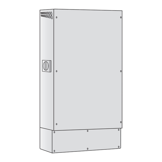
Page 12: Names Of Parts
Names of Parts ■Hybrid Solar Inverter Vents Front Panel DC Switch-disconnector Hybrid Solar Inverter Base ■Remote Controller Display Displays functions that are executed from the below operating buttons shown on the panel. (Indications change according to the screen.) Press the operating buttons below to execute the desired functions. - Page 13 Display The home screen is the screen that is typically displayed while the Hybrid Solar Inverter is running. The indicated amount of GENERATION, CHARGE/DISCHARGE, BUY/SELL, and NOTE CONSUMPTION are not completely accurate. Use them as a reference. (This product is not subjected to regulations under the Weights and Measures Law.) Time/Date Operating Status Displays the current time, day, month and year.
-
Page 14: Notes On Usage
Notes on Usage ■Ensure a minimum of 800 mm (31.5 in) in front, a The Hybrid Solar Inverter is for outdoor use. minimum of 500 mm (19.7 in) on the left, and 200 mm (7.8 in) above and on the right of the ■Secure a location for the inverter that meets the inverter for equipment checks and maintenance. -
Page 15: Before Using The Inverter For The First Time
Before Using the Inverter for the First Time Before using the inverter for the first time, have the installer perform the operations described below in the “Preparations” and “System Startup” sections. Preparations Set the grid-tied breaker in the Electrical Service Entrance to the ON position. System Startup Check the operating status of the inverter. -
Page 16: Grid-Tied Operation
Grid-tied Operation ■Daily Operation Time of Day Night Morning Remote Controller (Example) Remote Controller (Example) PEAK CUT Mode If there is an insufficient amount of sunlight, The storage batteries are discharged to charging/discharging is stopped. *2, 4 supplement power shortages (Discharges in order to cut peak). - Page 17 Daytime Evening Remote Controller (Example) Remote Controller (Example) If the amount of sunlight increases, surplus solar The storage batteries are discharged to power is used to charge the storage batteries. supplement power shortages (Discharges in *4, 5, 6, 8 order to cut peak). *2, 3, 4, 7 Remote Controller (Example) Remote Controller (Example) The storage batteries are discharged to supplement...
-
Page 18: Controlled Output
Grid-tied Operation ■Controlled Output If “VOLTAGE REGULATION” appears on the Display If “TEMPERATURE SUPPRESSION” appears on the Display Excessively high voltage from the commercial Excessively high temperatures inside the inverter p o w e r g r i d c a n h a r m e l e c t r i c a p p l i a n c e s . I f can harm the equipment. -
Page 19: If An Outage Occurs On The Commercial Power Grid
■If an Outage Occurs on the Commercial Power Grid If an outage occurs on the commercial power grid, an error message and error code are displayed on the Remote Controller. In an outage on the commercial power grid, the inverter temporarily stops operating. -
Page 20: Stand-Alone Operation (In A Power Outage)
Stand-alone Operation ( In a Power Outage ) Stand-alone Operation Precautions WARNING Do not connect the electric appliances listed below to the stand-alone outlets. The amount of electric power generated during stand-alone operation varies according to weather and storage battery charge. The inverter stops stand-alone operation if it generates less electric power than that consumed by the electric appliances connected to its stand-alone outlets. - Page 21 During the morning and daytime hours, the solar panels and storage batteries cooperatively supply the electric power necessary for household consumption. Surplus power is used to charge the storage batteries. During the evening and nighttime hours, power is supplied by the storage batteries. ●...
-
Page 22: Stand-Alone Operation Startup (Power Outage)
Stand-alone Operation ( In a Power Outage ) ■Stand-alone Operation Startup (Power Outage) After a power outage occurs, an error message appears on the screen and the inverter automatically switches from grid-tied operation to stand-alone operation. After a power outage has been detected, After about 10 seconds, the Remote error code “gxxx”... -
Page 23: Restoration Of Grid-Tied Operation
■Restoration of Grid-tied Operation If power is restored on the commercial power grid during stand-alone operation, the inverter automatically reengages grid-tied operation. Once input from the commercial power grid is detected, “GRID CONNECT→” appears on the Remote Controller for a few minutes. -
Page 24: Operation During A Power Outage
Stand-alone Operation ( In a Power Outage ) ■Operation during a Power Outage Power Outage Occurs Remote Controller (Example) Remote Controller (Example) GRID ABNORMALITY DETECTED. WILL RESTART IN 5 MIN. ONCE GRID IS BACK TO NORMAL. PLEASE CONTACT THE SERVICE CENTER IF THE ERROR MESSAGE CONTINUES MORE THAN 5 MIN. - Page 25 Morning - Afternoon Remote Controller (Example) Remote Controller (Example) The storage batteries are discharged to supplement If the amount of sunlight increases, surplus solar power shortages when there is an insufficient power is used to charge the storage batteries. *1 amount of sunlight.
-
Page 26: How To Stop Inverter Operation
How to Stop Inverter Operation ■To Stop the Hybrid Solar Inverter Press and hold the [RUN/STOP] button on the Remote Controller for 5 seconds or more. NOTE •Standby power is consumed even while the inverter is stopped. •Do not leave the grid-tied breaker in the Electrical Service Entrance in the OFF position for long periods of time. - Page 27 ■ In case of stand-alone over current error (e010) ● Some appliances draw too much inrush current at starting, which exceeds output capacity of the inverter. This may cause of an e010 error. ● In case of this error, the inverter might be recovered by disconnecting appliances and/or turning off the switch on Backup Load Panel.
-
Page 28: Settings
Settings [1]Setting the Date and Time Press [SETUP] on the home screen. Select “DATE & TIME” using [↓] and press [ENTER]. Set the DATE and TIME. • Press [CHANGE] to change numeric values. • Press [→] to move to the next digit. After entering the DATE and TIME, select “SAVE”... - Page 29 [2]Setting the Screen Brightness and Lighting Time Press [SETUP] on the home screen. Select “SCREEN BRIGHTNESS” using [↓] and press [ENTER]. Select the screen brightness using [CHANGE] and press [ENTER]. Select the lighting time using [CHANGE] and press [ENTER]. Check the settings on the display and press [ENTER]. •...
- Page 30 Settings [3]Setting the Generation Start Date Press [SETUP] on the home screen. Select “GENERTION START DATE” using [↓] and press [ENTER]. Input the “GENERATION START DATE.” • Press [CHANGE] to change numeric values. • Press [→] to move to the next digit. After entering the GENERATION START DATE, select “SAVE”...
- Page 31 [4]Setting the Energy Saving Assist Target Press [SETUP] on the home screen. Select “ENERGY SAVING ASSIST” using [↓] and press [ENTER]. Select the numeric value next to “TARGET” using [→]. The cursor moves in the order of the 4th (highest) digit → 3rd digit →...
- Page 32 Settings [5]Changing Operation Mode Press [SETUP] on the home screen. Select “OPERATION MODE” using [↓] and press [ENTER]. The operating mode changes in the following order of MAX POWER EXPORT Mode, ECONOMY Mode, HOME BACKUP Mode and PEAK CUT Mode by pressing [CHANGE] from the OPERATION MODE menu.
- Page 33 Select "SAVE" and press [ENTER]. Propriety of setting in each mode are as follows. CHARGE DISCHARGE1 DISCHARGE2 CHARGE DISCHARGE1 DISCHARGE2 DEPTH OF MODE TIME TIME TIME PROCEDURE THRESHOLD THRESHOLD DISCHARGE 〇 〇 × × × × 〇 MAX POWER EXPORT ×...
- Page 34 Settings [6] Setting the Time Zone/DST Press [SETUP] on the home screen. Select “TIME ZONE/DST” using [ ↓ ] and press [ENTER]. Change the time zone using [CHANGE]. ● Select “DST” using [ ↓ ]. ● Change the DST using [CHANGE]. Select “SAVE”...
-
Page 35: Configuring The Connection To The Internet
Configuring the Connection to the Internet Enabling the connection to the Internet allows remote controller software to be constantly updated to the most current state. ● Connect the remote controller to the Internet to perform the required update. ● You can check for the availability of updates by using [INFO] on the remote controller. Internet Connection Procedure ■... - Page 36 Configuring the Connection to the Internet 2. Connecting devices ■ Network configuration schematic diagram Remote controller Area of customer responsibility WAN port Line terminating equipment (modem, etc.) LAN port Data center Internet service LAN cable connection Router ■ Connecting LAN cables (Connecting LAN cables between the remote controller and router) Remove the remote controller.
- Page 37 3. Network settings Use the remote controller to configure the settings necessary to connect to the Internet. You have two options available to configure the settings. 1. Automatic configuration of network settings (enabling DHCP) 2. Manual configuration of network settings (disabling DHCP) [1] Automatic configuration of network settings (enabling DHCP) Press [SETUP] at the home screen.
- Page 38 Configuring the Connection to the Internet Press [ ↓ ] to select “NETWORK SETTING” and press [ENTER]. ● This displays a screen of the current settings. Press [ENTER] on the screen displaying the current settings. ● If your are configuring network settings for the first time, press [ENTER] to acquire network settings (address information).
- Page 39 ■ Displayed IP address, net mask, gateway, and DNS information is not correct ● All values on the screen are zeros This is likely due to a wiring issue between the remote controller and the router. Recheck the following items. Check Items ●...
- Page 40 Configuring the Connection to the Internet [2] Manual configuration of network settings (disabling DHCP) Manually configure the network settings when you have configured your network yourself or when the router address is manually configured. Enter an IP address and other network information applicable to your network environment configuration.
- Page 41 Press [ENTER] on the screen displaying the current settings. ● This displays the current network settings. Press [ ↓ ] to select the desired parameter and press [ENTER]. ● This displays the screen to configure the selected parameter. * Net mask refers to the subnet mask and gateway refers to the default gateway.
- Page 42 Configuring the Connection to the Internet After all parameters have been configured, select “MANUAL (FIXED)” and press [ENTER]. ● This enables the entered settings and returns to the network settings screen. Move the cursor to “MANUAL” to change the button in the lower-right from [CHANGE] to [ENTER].
- Page 43 Check the result of the communication test. ■ Display of “OK” Press [BACK] to return to the home screen. ■ Display of “FAILED” ● “FAILED” appears as the result when the communication test fails. ● Check the details that appears under “TEST RESULT” and refer to “Troubleshooting communication test failures”.
- Page 44 Configuring the Connection to the Internet ■ Confirming software updates Press [INFO] at the home screen. ● This displays the update confirmation screen and information about the update. Updates available No updates available ● Customers must procure and configure their Internet service. If you need assistance or have questions, consult with your dealer.
-
Page 45: Viewing System Records
Viewing System Records [1]Viewing Power Generation and Consumption Records Press [RECORD] on the home screen. • A screen appears where you can select the type of record to view. Select “GENERATION/CONSUMPTION” using [↓] and press [ENTER]. • A screen appears where you can select a time interval for displaying your power generation and consumption. - Page 46 Viewing System Records The power generation and consumption recorded for your system is displayed. • The below displays are examples of what appears when TODAY is selected. HOURLY, DAILY and MONTHLY displays are operated in the same way. [CHART] [NUMERIC] How to read the graph How to read the table Power graph...
- Page 47 [2]Viewing Power Selling and Buying Press [RECORD] on the home screen. • A screen appears where you can select the type of record to view. Select “SELL/BUY” using [↓] and press [ENTER]. • A screen appears where you can select a time interval for displaying your power selling and buying.
- Page 48 Viewing System Records The power generation and consumption recorded for your system is displayed. • The below displays are examples of what appears when TODAY is selected. HOURLY, DAILY and MONTHLY displays are operated in the same way. [CHART] [NUMERIC] How to read the graph How to read the table Power graphs...
- Page 49 [3]Viewing Cumulative Records from the Power Generation Start Date Press [RECORD] on the home screen. • A screen appears where you can select the type of record to view. Select “FROM GENERATION START DATE” using [↓] and press [ENTER]. • A screen appears where you can select cumulative records from the power generation start date.
- Page 50 Viewing System Records The cumulative records for your system are displayed. How to read the information <GENERATION> Displays the total amount of power generated since the system started generating power. When the inverter is detached, the display will not correctly show information.
-
Page 51: Energy Saving Assistance
Energy Saving Assistance [1]Setting the Energy Saving Assist Target Press [SETUP] on the home screen. • A screen appears where you can select setting items. Select “ENERGY SAVING ASSIST” using [↓] and press [ENTER]. • A screen appears where you can input a consumption target. Input a consumption target. - Page 52 Energy Saving Assistance [2]Viewing Energy Saving Assist Records Press [RECORD] on the home screen. • A screen appears where you can select the type of record to view. Select “ENERGY SAVING ASSIST” using [↓] and press [ENTER]. • The ENERGY SAVING ASSIST screen appears. The Energy Saving Assist records of your system are displayed.
-
Page 53: Troubleshooting
Troubleshooting Troubleshoot problems as shown Check the error code on the below. If it is determined that servicing Remote Controller. is necessary, contact the service center. Look up the error code on the following page. Follow the directions as given in the error message. -
Page 54: Error Code
Troubleshooting Error Message (Troubleshooting) Error Code DETECTED ABNORMALITY INSIDE INVERTER. D015, D025, D035, B103 - B104, B106, PLEASE CONTACT THE SERVICE CENTER. T001, T003, T004, T006 b101, b109 - b110, DETECTED ABNORMALITY INSIDE INVERTER. PLEASE CONTACT E001, E012, E014, E016, E019, E020, THE SERVICE CENTER IF THE ERROR MESSAGE CONTINUES MORE e001, e012, e014, e016 - e020, e024, THAN 5 MINUTES. - Page 55 Error Message (Troubleshooting) Error Code REMOTE CONTROLLER IS NOT WORKING PROPERLY. R-02, R-03 PLEASE CONTACT THE SERVICE CENTER. IF OPERATION MODE CANNOT BE SYNCHRONIZED AFTER REST ARTING BY RUN/STOP BUTTON MANUALLY, PLEASE CONTACT r-14 THE SERVICE CENTER. DATA COPY FAILED. r-15 INSULATION/GROUND FAULT DETECTED.
-
Page 56: Equipment Checks And Maintenance
Equipment Checks and Maintenance ■Routine Equipment Checks • Check the following items once a week to prevent equipment issues. (Check interval: Once weekly) Check item Troubleshooting Are vents covered in dust or by objects? Stop inverter operation and wait for the inverter to cool down completely. -
Page 57: Maintenance Schedule
■Maintenance Schedule 10 Y 15 Y 20 Y Maintenance Schedule ears ears ears ears Periodic checks (Once a month) Perform monthly checks. * Monthly checks are performed by the user. Inverter Replacement Replacement Replacement (Every 10 years) * Equipment tends to degrade over time, therefore users should consider replacing the equipment every 10 years. ■How to Clean Hybrid Solar Inverter Remove dust from vents and clean the front and back of the Hybrid Solar Inverter. -
Page 58: Specifications 58
Specifications Item Specifications ated charging maximum continuous output current C 16.5 A aximum charge / discharge current C 26 A torage Battery Input / ominal output voltage C 86.4 V utput umber of input circuit circuit harging output voltage operation range C 60 - 95 V ange of input operating voltage C 80 - 550 V... - Page 59 Arc Fault Circuit Protection The inverter is certified to UL1699B. It has protection circuit for arc fault caused by photovoltaics.
- Page 60 Tabuchi Electric Co., Ltd. DOC01-DS1613-AJ...
Need help?
Do you have a question about the THD-S55P3B-US and is the answer not in the manual?
Questions and answers