Table of Contents
Advertisement
Advertisement
Table of Contents

Summary of Contents for Fiber Options S711D
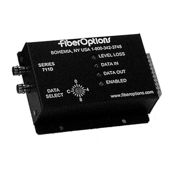
- Page 1 . . . light years ahead ™ S711D & S7711D UNIVERSAL DATA TRANSMISSION SYSTEM...
- Page 2 This apparatus does not exceed the Class A limits for radio noise emission set out in the Radio Interference Regulation of Industry of Canada. Cet appareil numerique de la classe A respecte toutes les exigences du Reglement sur le materiel brouilleur du Canada. PART 15 COMPLIANT S711D & S7711D Instruction Manual...
-
Page 3: Installation
Unpacking the Unit NOTE: The series numbers S711D, S711D-T and S711D-R will be used to describe all models of transmit- In the event that anything is missing from the following ters and receivers unless noted otherwise. - Page 4 S711D & S7711D - CONNECTORS, JUMPERS, SWITCH SETTINGS, DIMENSIONS FIGURE 2: CONNECTOR, SWITCH, AND LED LOCATIONS FIGURE 4: ROTARY SWITCH SETTINGS RACKMOUNT CARDS (SW1 OR DATA SELECT): Setting Mode Disable (factory preset) FIGURE 3: CONNECTOR, SWITCH, AND LED LOCATIONS STANDALONE MODULES...
- Page 5 8-PIN DATA CONNECTION TABLES - RACK-MOUNT CARDS - S711D S7711D TABLE 1: TABLE 2: TABLE 3: RS232 Interface RS232 with Handshaking Interface TTL Interface Mode Switch SW1: Position 1 Mode Switch SW1: Position 2 Mode Switch SW1: Position 3 Pin No.
- Page 6 S711D & S7711D - STANDALONE MODULES - 10-PIN DATA CONNECTION TABLES TABLE 10: TABLE 11: TABLE 12: RS232 Interface RS232 with Handshaking Interface TTL Interface Data Select switch: Position 1 Data Select switch: Position 2 Data Select switch: Position 3 Pin No.
-
Page 7: Module Setup
Data Connections: Connect the data cable to the remov- enclosure until the edge connector at the back of the card able 8-pin or 10-pin screw terminal on the S711D accord- seats in the socket. Seating may require thumb pressure ing to Tables 1 - 18 for the data format selected above. -
Page 8: Maintenance
Fiber Options’ technical support at: OPERATION TOLL FREE: 800-342-3748 S711D links operate automatically once installed. To exe- PHONE: 631-567-8320 cute the test mode, see page 7. For an explanation of LED color codes, see LED OPERATION and Table 20. -
Page 9: Rs485 Application Notes
The S711D has a +5 V bias pin and ground pins on the con- nector for this purpose. Contact equipment manufacturer's 4. The test receiver (position 9) should behave as follows: technical support for recommended resistor values and configuration. -
Page 10: Led Operation
DATA IN: The DATA IN LED indicates the level of the data D. Level /Loss should be green to off (but not red), indi- being input to the S711D over copper. A GREEN LED indi- cating that sufficient optical power is being received. - Page 11 DATA TRANSLATIPONS AND LED DIAGNOSTIC INDICATORS - S711D S7711D TABLE 19: DATA TRANSLATIONS NOTE: When configuring a pair of transceivers to translate data, the unit originating a signal is considered the transmitter and the unit receiving and translating the signal is considered the receiver.
- Page 12 . . . light years ahead ™ S711D & S7711D: UNIVERSAL DATA TRANSMISSION SYSTEM All specifications are subject to change without notice. Information furnished by FIBER OPTIONS is 11-0711D-Rev B believed to be accurate and reliable. However, no responsibility or liability is assumed by FIBER Copyright 2001 by FIBER OPTIONS.
- Page 13 Refer to Table 3 for a key to the LED functions. Fiber Options Inc., 80 Orville Drive, Bohemia, NY 11716-2533 Phone: 516-567-8320 or 1-800-342-3748; Fax: 1-877-FiberFax (1-877-342-3732 toll free) or 516-567-8322 Internet: www.fiberoptions.com...
- Page 14 Table 1 Pin Connections for Data Connector J2 Pin No. Function Contact closure in, ground Contact closure in Contact closure out Contact closure out Ground Not connected Ground Data In/out Table 2 Pin Connections for Power Connector Pin No. Function +13 to 16 VDC Not connected Ground...
Need help?
Do you have a question about the S711D and is the answer not in the manual?
Questions and answers