Table of Contents
Advertisement
Quick Links
Advertisement
Table of Contents

Summary of Contents for ImageWorksVeterinary ImageVet DC
- Page 1 ImageVet DC Operation, Assembly & Installation Manual Rev. 4.1 June 2015...
-
Page 2: Table Of Contents
OPERATION INSTRUCTIONS 1. General precautions 1.1. Description of the symbols used 1.2. Purpose and use of the equipment 1.2.1. Classification 1.2.2. Environmental conditions 1.2.3. Guarantee 2. Description of the system 2.1. Description of the X-ray unit 2.2. Operating mode 3. Operation 3.1. - Page 3 INSTALLATION & ASSEMBLY INSTRUCTIONS (WALL MOUNT - CONT’D) 4. Installation 4.1. Positioning the X-ray unit’s yoke 4.2. Wall-mounted plate for supporting the X-ray unit 4.2.1. Vertical single stud installation with wooden post 4.2.2. Horizontal double stud installation with wooden post 4.2.3.
-
Page 4: General Precautions
1. General precautions These instructions explain how to properly use the X-ray unit. Please carefully read and become familiar with the content of this manual before attempting to use the apparatus. NOTE: This manual does not specify the rules and regulations for acquiring, possessing or using a source of ionizing radiation as each country has its own laws. -
Page 5: Purpose And Use Of The Equipment
1.2. Purpose And Use of the Equipment This X-ray unit is designed for use in veterinary dentistry to provide intra-oral X-rays for diagnostic purposes. This equipment can be used to produce film X-rays developed with chemicals, or digital images from photo-phospher plates, or digital X-ray sensors. 1.2.1. -
Page 6: Description Of The System
Description of the system 2.1. Description of the X-ray unit Description of the parts: a X-ray tubehead. Depending on the operating mode, the high frequency constant potential X-ray tubehead works at 60KV 7mA (En60 mode), 63KV 6mA (En63 mode) or 65KV 6mA (En65 mode). Rotation is limited by mechanical end-stops. -
Page 7: Operation
3. Operation 3.1. Turning the X-ray unit on and off 3.1.1. Turning on the X-ray unit The central control unit is turned on and shut off with switch (A). The switch lights up to signal the central control unit is energized. NOTE: The technical specifications of the switch are given in paragraph 1.2.2. -
Page 8: Automatic Remote Shut Off
3.1.3. Automatic remote shut off Once the central control unit has been turned off, the remote automatically shuts off after approximately one minute. The remote also automatically shuts off when it is further than the maximum allowable distance from the control until. 3.1.4. -
Page 9: Checking The Parameters
NOTE: The main functions of the keys on the remote vary according to how they are pressed: BRIEFLY PRESSED (less than 3 sec.) PRESSED LONGER (more than 3 sec.) Changes over from LARGE to SMALL and vice Saves the selected setting (exposure time, sensitivity, etc…). The versa (takes place when key is released). -
Page 10: Factory Settings
• Checking the selected type of intraoral exam. Upper PreMolar/Molars Upper Canines Incisors Lower Canines Lower PreMolar/Molars 3.5. Factory settings The X-ray unit is supplied with the following factory settings: • Operating mode: AUTO • Sensitivity: Level 17 • Remote stand by: 5 minutes •... -
Page 11: Using The X-Ray Unit
Using the X-ray unit Position of the patient Patients may be in sternal, dorsal or lateral recumbancy on a wet table. 4.2. Positioning the X-ray head Position the X-ray head so that the cone is aligned at the desired angle. There is an angulation bezel provided for those who prefer to work with specific angles (either sternal or dorsal recumbancy). -
Page 12: Setting The Exposure Mode And Time
4.4. Setting the exposure mode and time The exposure parameters are set by following the directions given below: 1) select the tooth to be examined 2) select the patient size The exposure time is automatically shown on the remote screen. NOTE: Each operating mode (En60, En63 or En65) is displayed for approximately 1 second according to the tooth or patient size just selected. -
Page 13: Procedure To Be Followed When Taking The X-Ray
To deactivate USER mode, press keys again (icon goes off). The exposure parameters are set as directed below: 1) select the tooth under examination. 2) select the patient size. The exposure time is automatically displayed on the remote. NOTE: It is not possible to access the sensitivity factor menu in USER mode. In addition, keys inoperative in USER mode. -
Page 14: Advanced Options
• Once the maximum temperature has been reached, the pause time for cooling will be signaled by symbol • At this point the exposure function will be disabled until the screen shows “READY” again. • As soon as “READY” appears on the remote, another exposure may be taken. 5. -
Page 15: Restoring Factory Settings
5.3. Restoring factory settings To restore the factory settings (see paragraph 3.5) press keys to go to the set up menu. Press keys simultaneously. "rESS" will briefly appear and the remote will be rebooted. 6. Error messages NOTE: In presence of strong wireless communication traffic, the connection between the remote and the main control may break down.To restore the connection, run the “Restoring factory settings”... -
Page 16: Routine Maintenance
7. Routine maintenance ATTENTION! Any technical maintenance work required must be carried out by qualified personnel or by a specialized technician authorized by the manufacturer. It is the user’s responsibility to check that routine maintenance is carried out by an authorized technician at least once every 2 years. The maintenance methods are specified in the Technical Service Manual in possession of an authorized technician. -
Page 17: Dismantling The Equipment When No Longer Used
9. Dismantling the equipment when no longer used As set out in Directives 2002/95/ EC, 2002/96/ EC and 2003/108/ EC, on the restrictions of the use of certain hazardous substances in electrical and electronic equipment along with collection, treatment, recycling and disposal of waste, electrical and electronic equipment, the latter must be treated as municipal waste, therefore sorted and collected separately. - Page 18 X-RAY TUBE: • X-ray tube: TOSHIBA D-0711. • Focal spot: 0.7mm in accordance with IEC 336 / 1993. • Tolerance of focal spot position on reference axis : ± 2%. • Nominal high voltage and maximum current: (65KV, 7mA) ± 10%. •...
-
Page 19: Dimensions
11. Dimensions SIDE VIEW All dimensions are expressed in millimeters (inches). 400/600/900 1340 ( 2. 4 ) (15.7/23.6/35.4) (52.8) 2 65 ( 1 0.4) 8 90 / 10 90 / 13 90 ( 35 .0 / 4 2.9 / 5 4 .7) (15.7) 1 49 0 / 169 0 / 1 9 90 ( 58 . - Page 20 TOP VIEW 4 5 0 ° 1 5 ° 400/600/900 (15.7/23.6/35.4) 1 4 9 0 / 1 6 9 0 / 1 9 9 0 ( 5 8. 7 / 6 6 .5 / 7 8 .3 ) 2 0 2 0 / 2 2 2 0 / 2 5 2 0 (7 9.
- Page 21 12. Identification nameplates WARNING! Never remove the identification nameplates provided on the tube head, central control unit or collimator cone. Central control unit The nameplate is found beside the main switch. Details shown on the nameplate: • Name of the manufacturer •...
- Page 23 SIDE VIEW 400/600/900 1340 ( 2. 4 ) (15.7/23.6/35.4) (52.8) 2 65 ( 1 0.4) 8 90 / 1090 / 13 90 ( 35 .0 / 4 2.9 / 5 4 .7) ( 15.7) 1 490 / 169 0 / 1 9 90 (58 .
- Page 24 TOP VIEW 4 5 0 ° 1 5 ° 400/600/900 (15.7/23.6/35.4) 1 4 9 0 / 1 6 9 0 / 1 9 9 0 ( 5 8. 7 / 6 6 .5 / 7 8 .3 ) 2 0 2 0 / 2 2 2 0 / 2 5 2 0 (7 9.
-
Page 25: General Safety Precautions
1. General safety precautions The manufacturer warranties the safety, reliability and performance of the equipment under the following conditions: - Installation and technical service is performed by authorized technicians using Cela Sc - Cela Dental Group original parts. - The electrical system in the dental area corresponds to standards I.E.C. 60364-7-710;V2 (Standards regarding electrical systems in a medical environment) or equivalent standards currently in force in the country where the equipment is installed. -
Page 26: Drawings
3. Pre-Installation Refer to the drawings on pages 23 and 24 to help determine the ideal extension arm length as well as proper distances from the floor to the bottom of the central control unit (timer assembly). 3.1. Mechanical Specifications If the wall is thin (hollow bricks or similar), use the optional Counter Plate (part no. -
Page 27: Installation
4. Installation The X-ray unit must be installed by a qualified technician in compliance with the installation instructions given below with regards to both the mechanical and electrical parts. WARNING ! Verify that the voltage indicated on the central control unit’s nameplate corresponds to that for the electrical system. - Page 28 4.2.1. Vertical single stud installation • Insert the 4 TPSEI M8x35 screws provided in the interface plate. • Run the power supply wires through one of the holes in the interface plate. • Attach the interface plate to the wooden post with no. 3 dia. 3/8’’ x L 3’’ wood screws (not supplied). •...
-
Page 29: Extension Arm
4.3. Extension arm Warning! Do not lubricate the pin of the extension arm: the wall-mounted plate is provided with self-lubricating bushings. Figure B • Insert the pin (b) of the extension arm (c) in the hole provided in the wall-mounted plate. •... -
Page 30: Bottom Mount Installation Extension Arm (Vertical)
4.3.1. Bottom mount installation extension arm (vertical) Fig. A Fig. B Check the direction of the pin support: it should be set as shown in Figure (A) for this type of installation. Insert the extension arm pin in the hole in the wall-mounting plate from below. Place the ring nut supplied on top of the pin and tighten the ring nut with the spanner wrench provided, as shown in the Figure (B). -
Page 31: Installing The Folding Arm
4.4. Installing the folding arm Warning! The arm is supplied bound together with a velcro strap. This strap should not be removed until the two free ends of the arm have been connected to their corresponding attachments: The extension arm (already secured to the wall) and X-ray tube head. If the strap is loosened prior to securing both ends in place, releasing it suddenly could hyper-extend the arm, resulting in damage. - Page 32 Figure F • Take the rotation stop screw (o) from the X-ray unit kit and tighten it at point H (tighten it fully and then loosen by ½ turn). NOTE: Turn the folding arm to check that the adjustment has been made properly. •...
-
Page 33: Installing The Tubehead
4.5. Installing the tubehead • Take the tubehead out of its packaging. • Lubricate the bushing of the folding arm and the tubehead pivot pin with bearing grease. Figure I... - Page 34 • Take the washer (a) from the kit supplied and place it in pin (b) with the protruding tooth (c) pointed towards the front of the head. (see Fig.K) Figure K Position the protruding tooth (c) of the washer (a) in zone 1 of the pin (b). (see Fig. L) Warning! Do not position the protruding tooth (c) of the washer (a) in zone 2 of the pin (b).
- Page 35 Figure M • Fit the connector of the folding arm cable to that of the tube head cable • Place them inside the hole provided (c) • Fit the plug (e) supplied into the hole then tighten the screw that is already in place. (see Fig. N) Figure N...
-
Page 36: Installing The Collimator
4.6. Installing the collimator • Take the collimator out of the packaging: Figure O • Insert into the tube head all the way until it clicks. -
Page 37: Balancing The Folding Arm
4.7. Balancing the folding arm This step is optional and may not be necessary with each installation/assembly. If the folding arm does not stay in a stable position, adjust the spring tension by using an 8mm allen wrench or “T” bar which should be at least 20cm long and adjust in the following manner: The folding arm segment that connects to the horizontal extension arm will be referred to as the vertical segment (a). -
Page 38: Wall-Mounted Plate Wiring Connections
4.9. Wall-mounted plate wiring connections • Connect the power cable (LINE) to terminal K2, observing the following positions: L - SUPPLY (brown wire) - GROUND (yellow/green wire) N - NEUTRAL (blue wire) • Connect the generator’s power cable to the respective connectors, observing the following positions: K6 - brown wire and blue wire. - Page 39 4.10. Completion of wall-mounting plate and holster for remote Figure S and Figure T • Take the cover (a) and place it over the wall-mounting plate fully tightening the phillips screws (b) provided and pre-installed on the plate. • Place the cover (c) in the area shown in the figure. The cover (d) will automatically snap into place when it is closed. •...
-
Page 40: Setup & Technician Setup Menus
5. Setup and Technician Setup menus The remote allows a number of work parameters to be viewed and edited by pressing a combination of keys present on the control panel. serves to confirm/save the function, key is used to undo/quit the menu while keys edit the values of the selected parameters on all the setup menus. -
Page 41: Restoring Factory Settings
5.1. Restoring factory settings To restore the factory settings press keys to go to the set up menu. Press keys simultaneously. “rESS” will briely appear and the remote will be rebooted. 5.2. Calibrating the X-ray head This operation requires the execution of 20 shots, at a pre-set time of 0.01 s, during which time X-ray emission occurs. It is therefore necessary to pay close attention to radiation safety protocols. -
Page 42: Central Control Unit Card P/N 97660515
6. Central control unit card P/N 97660515 1 2 3 4 5 6 1 2 3 NOTE: An interlock switch may be attached by cutting the brown wire that attaches to terminal K6 about two inches away. Splice in a wire to the supply end of the brown wire and route to one terminal of the interlock switch. -
Page 43: Basic Head Control Card P/N 97660514
7. Basic head control card P/N 97660514 1 2 3 4 5 6 FL_OUT GND_FIL V+15 BASIC HEAD CONTROL CARD CAP_SDA SCHEDA TESTATA RX DC CAP_CLK CONE_SW 97660514 HAND_SW1 HAND_SW2 DL1=DSP DL2=VDD DL3=CPU DL4=ERR DL5=NTWK DL6=CONE DL7=HNDL DL8=PWM DL9=ACT DL10=FIL V+15 EN_ACT EN_S/U... - Page 44 Diagnostic LED Indicators DSP LED Color Status Description Yellow Flashing If the diagnostic LED indicator flashes once a second everything is OK. If it flashes once every half-second, count the times it flashes and check the error table. When first turned on, the DSP executes internal diagnostics and then displays the FW version using two flashing sequences separated by pauses.
-
Page 45: X-Ray Tubehead
The DSP can also signal an alarm condition. This condition is signaled when LED DL1=DSP flashes faster than usual separated by pauses. The number of times it flashes between pauses indicates the alarm code. In the event of a CPU fault, the status of the CPU LEDs is as follows: •... -
Page 46: Pairing The Remote With The X-Ray Tubehead
8.1. Pairing the remote with the X-ray tubehead If the remote controller or the head control card P/N 97660514 needs to be replaced it is only necessary to associate the remote with the head. To do this, you first need to set the head in combination mode and then send a recognition signal from the remote control. 1) Setting the head in combination mode: This procedure can only be activated within ten seconds of the radiographic unit being turned on. - Page 47 8.2. Check occupation of radio frequencies for the remote The procedure described below enables the user to check the availability of radio frequencies on the channels of communication used by the remote control. Open the battery compartment of the remote and remove the batteries. See Fig. 1 Fig.
- Page 48 The remote should now be ready for radio frequency detection mode. Replace the batteries. When switched on, the display shows the channel to be examined (C11). Pressing chooses the channel (C11-C26). Pressing the key displays a percentage value representing the signal quality on the selected channel.
-
Page 49: Error Codes Given On The Remote
8.3. Error codes given on the remote When an error appears on the remote screen, it can be reset by pressing to set the X-ray unit back to “READY”. If the error is still displayed after pressing the two keys mentioned above, refer to the error code and solution given in the table below. Remote Errors N°... - Page 50 Error codes given on the remote (Cont’d) When an error appears on the remote screen it can be reset by pressing to set the X-ray unit back to “READY”. If the error is still displayed after pressing the two keys mentioned above, refer to the error code and solution given in the table below. Head Control Card Errors P/N 97660514 (Cont’d) N°...
- Page 52 ImageWorks Veterinary 14 Inverness Drive East Suite C130 Englewood, CO 80112 support@imageworksveterinary.com www.imageworksveterinary.com...
-
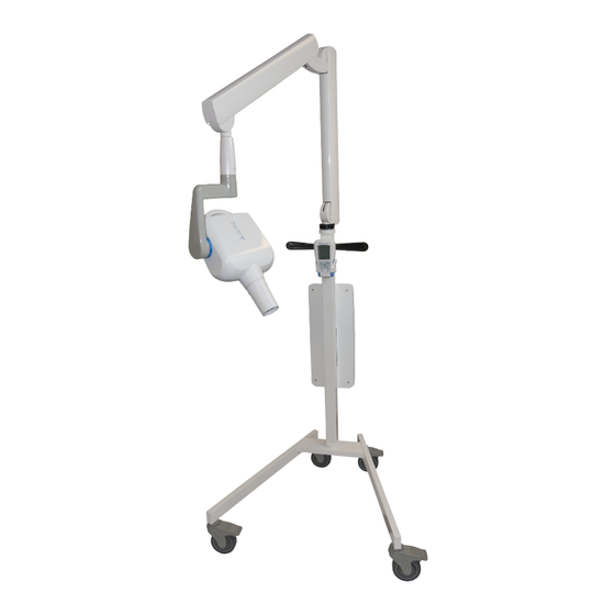
Page 53: Mobile System Assembly Instructions
ImageVet DC Mobile System Assembly Instructions Rev. 1.1 May 2015... - Page 54 1. Assemble Mobile Stand. Start by locating the hardware kit from within the mobile stand box. Note that the casters come pre-installed on the legs. Insert four(4) 8mm x 1.5” allen cap head bolts in 2 places for each leg, thus assembling the legs to the base.
- Page 55 4. Using the two 6mm Allen cap head bolts provided, mount the back plate onto the mobile stand upright, making sure the side with the sticker is facing you. New style 6mm Allen cap upright head bolt Fig. C Fig. D 5.
- Page 56 Install folding arm into mobile stand upright. Move the mobile stand near a table or chair that the folding arm can be placed upon. Then feed the folding arm wires down through the main hole in the top of the upright and gently pull the wires out of the same hole where the main power cable is placed.
-
Page 57: Electrical Connections
Make electrical connections from the folding arm cables and incoming power supply. Connector from folding arm Hex-Head bolts in four(4) places. Connector from folding arm Ground wires from folding arm Fig. L Fig. K Note: A jewelers flat head screw driver will be needed to attach power supply to the input header. - Page 58 Install front cover by engaging the bottom of the cover first (near the on-off switch) and then swinging the rest of the cover up and into place. Place Imageworks Vet logo sticker into the recess in the center. (See Fig a through d) ImageWorks Generations of Imaging a.
- Page 59 Install tubehead using the following instructions: Installing the RX DC Tubehead • Take the tubehead out of its packaging. • Lubricate the outside surface of the tube head pivot point with grease designed for bearings. Fig. N...
- Page 60 12. (Cont’d) Take the special washer (a) from the kit supplied and t it into the pin (b) with the protruding tooth (c) pointed towards the front of the tubehead. (see gure O) Fig. O Position the protruding tooth (c) of the special washer (a) into zone 1 of the pin (b). (See gure P) WARNING! DO NOT position the protruding tooth (c) of the special washer (a) into zone 2 of the pin (b).
- Page 61 12. (Cont’d) Insert the molex plug from the folding arm cable into the tube head pin while pushing the tube head up into the tube of the folding arm. The molex plug should partially come out the hole in the bottom of the tube head yoke. See figure R - item (c).
-
Page 62: Installing The Collimator
Installing the collimator Take the collimator out of the packaging: Fig. S Insert it into the tubehead all the way until it clicks. - Page 63 This step is optional and may not be necessary with each assembly. The folding arm may be adjusted in the following manner: If the folding arm does not stay in a stable position, adjust the spring tension by using an 8mm allen wrench or “T”...
- Page 64 14. (Cont’d) Make adjustments using the following procedure: Gently remove the end caps (f ) from the tubehead end of the horizontal segment (B) AND the upper end of the vertical segment (A). Using a small flatblade jewelers screwdriver, gently pry off the small white plastic cover (a) that covers the small phillips screw (b) underneath.
- Page 65 14. (Cont’d) The vertical segment (A) should be pulled out to an approximate 45 degree position to allow access to the main lead screw before inserting the 8mm allen wrench for adjustment. A step ladder will normally be needed to make this adjustment. Adjusting the vertical segment Fig.
- Page 66 Finally, screw in the two black plastic handles provided into the holes near the top of the upright on both the left and right sides. Fig. Z Assembly is now complete. ImageWorks Veterinary 14 Inverness Drive East Suite C130 Englewood, CO 80112 support@imageworksveterinary.com www.imageworksveterinary.com...
Need help?
Do you have a question about the ImageVet DC and is the answer not in the manual?
Questions and answers