Table of Contents
Advertisement
Advertisement
Table of Contents

Summary of Contents for HiBot TITech M4
- Page 1 TITech M4 Controller v.1.2 ユーザーマニュアル User manual www.hibot.co.jp...
- Page 2 HiBot Corporation TITech M4 Controller ® User Manual HB-UM-M4CTRL...
-
Page 3: Table Of Contents
目次/Table of contents はじめに/Introduction ..................製品概要 ......................定格/Electrical characteristics ..............外観/Board dimensions ................コネクタ一覧/Connectors and housing ............機能説明 / Features ..................... ホールセンサ入力 / Schematic block ............ CAN ports ....................Accelerometer and Magnetometer .............. Gyroscope ....................LAN port ....................MicroSD port ..................... LEDs ...................... -
Page 4: はじめに/Introduction
This manual introduces the HiBot Titech M4 Controller ® board. HiBot Titech M4 Controller board is based on the STM32 ARM Cortex M4 STM32F407IG. For detailed chip hardware manuals, user is requested to check the documentation available online on the chip maker STMicroeletronics. -
Page 5: 外観/Board Dimensions
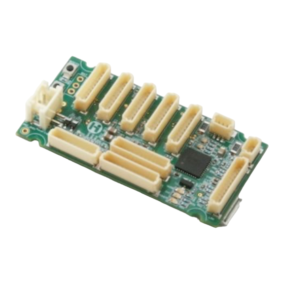
HiBot Corporation TITech M4 Controller ® User Manual 外観/Board dimensions 図/Figure 1 - Titech M4 Controllerの外観/Titech M4 Controller Titech M4 Controller 図/Figure 2 – Titech M4 Controllerの寸法図/ dimensions HB-UM-M4CTRL... -
Page 6: コネクタ一覧/Connectors And Housing
HiBot Corporation TITech M4 Controller ® User Manual コネクタ一覧/Connectors and housing The board is supplied with JTAG cable, shown in Figure 3, it can be utilized in connection with any debugger programmer for STM32 cores. This documentation will refer to the debugger/programmer device ST-LINK/V2 which is also available from the HiBot e-shop. -
Page 7: 機能説明 / Features
LAN interface Figure 5 - Board schematic block Titech M4 Controller is equipped with on board motion sensor unit consisting of a digital accelerometer and magnetometer LSM303DLHC and the Gyroscope L3GD20. Connectivity to other devices can be carried out not only by UART but also utilizing two CAN ports and/or LAN ethernet communication. -
Page 8: Accelerometer And Magnetometer
Figure 6 - CAN port 1 utilized as a termination Figure 7 - CAN port 2 utilized as a network node Titech M4 Controller can be utilized as a master or as a node together with other HiBot micro controller based boards... -
Page 9: Gyroscope
HiBot Corporation TITech M4 Controller ® User Manual Figure 9 - Accelerometer and Magnetometer on board. Gyroscope Figure 10 shows the orientation of the gyroscope which is installed in the bottom layer of the board. The chip supplies also temperature measurements that might be utilized for precise adjustments due to the environment temperature. -
Page 10: Lan Port
100nF 10uF/10V 3.3V HiBot Corporation TITech M4 Controller ® User Manual LSM303DLHC Jumper(2 pads) The chip can be accessed by the I2C connected to PB8 and PB9 pins of the micro 0.22uF/25V PA1_MI I_RX controller as shown in the following Figure 11. - Page 11 ® User Manual Figure 12 - LAN interface User can make use of the cable offered on HiBot homepage depicted in Figure 4 or can assemble a cable with transceiver following the schematics available in Figure 13 ! 1 1...
-
Page 12: Microsd Port
HiBot Corporation TITech M4 Controller ® User Manual LED_SPEED+ LED_SPEED- LED_LINK- LED_LINK+ CN12P_1 CN12P_1 M4 board CN7 RJ45 with transformer JST SHR-12V-S-B TAIMAG RJLD-260TC1 (HiBot HB-SHR12-001) Figure 13 - Connection between LAN port and RJ45 transceiver MicroSD port Figure 14 shows the connection to the microcontroller pins of the microSD card reader. -
Page 13: Leds
HiBot Corporation TITech M4 Controller ® User Manual LEDs A total of four LEDs are available on board. User can access them by setting as digital output pins PE0, PE1, PE3 and PE4 as shown in Figure 15. When the correspondent digital out pin is set as low level, the respective LED will be switched on. -
Page 14: 放熱 / Installation Of The Board And Dissipation
HiBot Corporation TITech M4 Controller ® User Manual 放熱 / Installation of the board and dissipation When installing the board for applications, the holes available on the board should be utilized taking care of avoiding any contact of the board surfaces with conductive materials. -
Page 15: コネクタのピン/Pin Assignment
HiBot Corporation TITech M4 Controller ® User Manual コネクタのピン/Pin assignment ! 1 5 HB-UM-M4CTRL... - Page 16 HiBot Corporation TITech M4 Controller ® User Manual ■保証 -1- 保証期間 株式会社ハイボットは、本製品を納入日から6か月間にわたり保証いたします。 -2- 保証の制限 ■修理の制限 株式会社ハイボットの責に帰する不具合が保証期間内に生じた場合、瑕疵のある当該製品 を直ちに修理または交換させていただきます。ユーザサポートは、本保証における救済に含ま れません。 ■損害の制限 本保証は、瑕疵のある製品のみに適用され、かかる製品の故障から生じるその他のいかな る損害にも適用されません。 本製品の損傷が以下のいずれかに起因する場合、本保証は適用されません。 1) 購入者による不適切な取り扱い/使用 2) 購入者による他の工具/機械の使用 3) 第三者による変更/修理 4) 何らかの自然災害/人為災害 ■保証に関するその他の制限事項 株式会社ハイボットは、本製品の瑕疵に起因する通常損害、派生損害、付随的損害、また は特別損害に対していかなる責任も負いません。また、本製品の不適切な使用または改造によ る本製品の不具合または損傷についても、かかる使用または改造により第三者にもたらされ得 る不具合または損傷についても、一切の保証をいたしません。さらに、本製品にインストール されたデータの偶発的な喪失につき、いかなる保証もいたしません。 本製品および付属ドキュメントは、現状有姿のまま提供され、その特定目的適合性に関し て、いかなる保証も行われず、また、暗示されるものでもありません。本製品の使用または故 障の結果として生じた損害賠償請求に対し、株式会社ハイボットは一切応じないものとしま す。...
-
Page 17: Warranties And Conditions
All informations, representations, links or other messages may be changed by HiBot at any time without prior notice or explanation to the user. In particular, HiBot is not obliged to remove any outdated information from its website or to expressly mark it as being outdated.
Need help?
Do you have a question about the TITech M4 and is the answer not in the manual?
Questions and answers