Chapters
Table of Contents

Summary of Contents for Pulsar TC-10B
- Page 1 TC–10B FREQUENCY-PROGRAMMABLE ON/OFF CARRIER TRANSMITTER/RECEIVER System Manual CC44–VER06 (Replaces CC44–VER05) 4050 N.W. 121st Avenue Coral Springs, FL U.S.A. 33065 1–800–785–7274 Technologies, Inc. www.pulsartech.com Printed October 2003...
- Page 2 Technologies, Inc.
-
Page 3: Table Of Contents
Product Description Applications and Ordering Information Installation Test Equipment Installation/Adjustment Procedures Signal Path TC–10B Design Verification Tests Maintenance System Manual Power Supply Module Keying Module Transmitter Module Table 10W PA Module RF Interface Module Contents Universal Receiver Module Receiver (solid state) Output Module Universal Checkback Module Optional Voice Adapter Module... -
Page 4: Product Description
Technologies, Inc. Important Change Notification This document supersedes the TC–10B Frequency-Programmable On/Off Carrier Transmitter/ Receiver System Manual CC44–VER05. The following list shows the most recent publication date for each chapter. Publication dates in bold type indicate changes to that chapter. For these chapters, the specific pages that have changed are listed for easy reference. - Page 5 PULSAR does not assume liability arising out of the application or use of any product or circuit described herein. PULSAR reserves the right to make changes to any products herein to improve reli- ability, function or design.
- Page 6 Any damage due to improperly packed items will be charged to the customer, even when under warranty. Pulsar Technologies, Inc. also makes available interchangeable parts to customers who are equipped to do repair work. When ordering parts (components, modules, etc.), always give the complete PULSAR style number(s).
-
Page 7: And Voice Adapter Modules
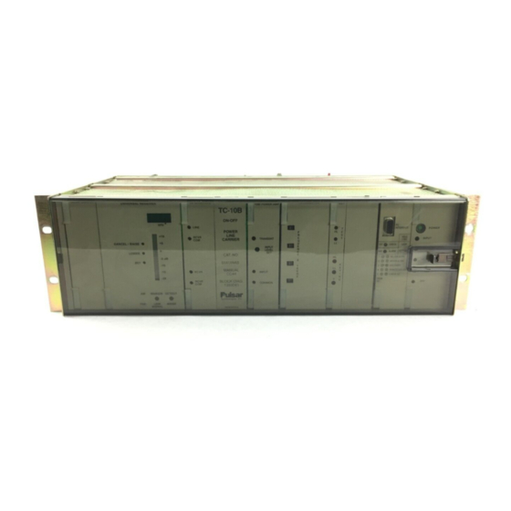
In addition, terms suspected of being trademarks or service marks have been appropriately capital- ized. Pulsar Technologies, Inc. cannot attest to the accuracy of this information. Use of a term in this book should not be regarded as affecting the validity of any trademark or service mark. - Page 8 Technologies, Inc. FIGURES Figure No. Page No. TC–10B Chassis and Control Panels with Optional Universal Checkback and Voice Adapter Modules .........1-9 Directional-Comparison Blocking, Basic Elements and Logic Diagrams .
- Page 9 Receiver Output Schematic ........15-7 16-1 Universal Checkback as part of a TC-10B ......16-4 16-2 Maximum Checkback Configuration with Timed Communications Mode .
- Page 10 Technologies, Inc. TABLES Table No. Page No. Transmitter/Receiver Specifications........1-3 Keying Specifications .
- Page 11 DIP Switch Setting Functions ........17-5 17-4 Default (Normal) Settings for TC-10B Operation ......17-5 October 2003...
- Page 12 Technologies, Inc.
-
Page 13: Standard Features
• dc-to-dc isolated power supply • 48, 125, and 250Vdc versions available Standard Nomenclature The standard nomenclature for PULSAR carrier protection equipment is as follows: Cabinet – contains fixed-racks, swing-racks, or open racks Rack – contains one or more chassis (e.g., the TC–10B) Chassis –... -
Page 14: Applications And Ordering Information
TC–10B System Manual Technologies, Inc. TC–10B Modules The TC–10B circuitry is divided into standard modules with optional Voice Adapter, TTL Transmitter and Universal Checkback modules available, as shown on the Functional Block Diagram (Fig. 6-1). Circuit descriptions, complete with schematic diagrams, are shown in Chapters 9 through 17 with Sub Numbers that indicate appropriate revisions for each module, as follows: Chapter Module... -
Page 15: Transmitter/Receiver Specifications
Chapter 1. Product Description SPECIFICATIONS The TC–10B meets or exceeds all applicable ANSI/IEEE standards. 1.5.1 Transmitter/Receiver Table 1-1 lists the Transmitter/Receiver specifications for the TC–10B. Table 1–1. Transmitter/Receiver Specifications. Frequency Range 30–535 kHz in 0.5 kHz (500Hz) steps, transmitter selection in 100Hz steps Ω... -
Page 16: Keying Specifications
TC–10B System Manual Technologies, Inc. Table 1–1. System Specifications (Cont’d). Minimum Channel Spacing Wideband 4 kHz Narrow band 2 kHz With Voice Adapter 4 kHz (both Narrow band and Wideband) An external hybrid or other device offering at least 20db rejection of the adjacent channel must be used in the application Channel Speed at 15dB Margin, Solid State Output Narrow Band (800Hz) -
Page 17: Receiver Output Specifications
Chapter 1. Product Description 1.5.3 Receiver Outputs Table 1-3 shows the TC–10B Receiver Output Specifications. Table 1–3. Receiver Output Specifications. Two independent relaying Both outputs (fully isolated) provide up to 1 A transistor switch outputs for microprocessor relaying or 200 mA (into 24Ω), 20mA (into Ω... -
Page 18: Voice Adapter Option Specifications
TC–10B System Manual Technologies, Inc. 1.5.6 Voice Adapter Option Table 1-6 shows the TC–10B Voice Adapter Option specifications. Table 1–6. Voice Adapter Option Specifications. Modulation Amplitude Modulation with compandor Transmission Half-Duplex Frequency Response 300Hz to 2 kHz Signaling Carrier alarm 1.5.7 Environmental Table 1-7 shows the TC–10B environmental specifications. -
Page 19: Altitude Dielectric Strength De-Rating For Air Insulation
Chapter 1. Product Description Table 1–8. Altitude Dielectric Strength De-Rating for Air Insulation Altitude (Meters) Correction Factor 1,500 1.00 1,800 0.97 2,100 0.94 2,400 0.91 2,700 0.87 3,000 0.83 3,600 0.79 4,200 0.74 4,800 0.69 5,400 0.64 6,000 0.59 Table 1–9. Altitude Correction For Maximum Temperature Of Cooling Air (ANS C93.5). -
Page 20: Power Requirement Specifications
TC–10B System Manual Technologies, Inc. 1.5.8 Power Requirements and Dimensions Table 1-10 shows the TC–10B power requirement specifications. Table 1–10. Power Requirement Specifications. Transceiver Supply Current (Amps) At Nominal Voltage Nominal Permissible Battery Voltage Receive/ 1 Watt 10 Watt Voltage Range Standby Transmit... - Page 22 TC–10B System Manual Technologies, Inc. USER NOTES Technologies, Inc. Page 1–10 October 2003...
- Page 23 Subscript 1 indicates relays at station G for absolute channel delay time. This comparison of breaker 1; subscript 2, relays at the local and remote square waves at each Copyright © 2003 Pulsar Technologies, Inc.
-
Page 24: Directional-Comparison Blocking, Basic Elements And Logic Diagrams
TC–10B System Manual Technologies, Inc. Breaker 1 Channel Breaker 1 Trip Start Fault Detectors (S 1 ) Fault Detector (P 1 ) Protected Line Power Line Carrier Channel Breaker 2 Trip Fault Detector (P 2 ) Breaker 2 Channel Start Fault Detectors (S 2 ) 2-1a –... -
Page 25: Phase-Comparison Blocking, Basic Elements
Chapter 2. Applications and Ordering Information Table 2–1. Directional Comparison Schemes for External and Internal Faults. SCHEME FOR EXTERNAL AND INTERNAL FAULTS Type of Fault Events at Station G Events at Station H External (F operates; S does not see operates to key transmitter. -
Page 26: Single Phase Comparison Blocking, Current Only Operation
TC–10B System Manual Technologies, Inc. 2.1.3 Single Phase- Comparison F I & F E Blocking, Current Protected Line Only In the current only system, the TC–10B is used with two overcur- Fault Detecting Logic Fault Detecting Logic rent fault detectors (FD and FD (Figure 2–2) (Figure 2–2) -
Page 27: Single Phase-Comparison Blocking, Distance-Supervised Operation
Chapter 2. Applications and Ordering Information 2.1.4 Single-Phase, Distance- Supervised Comparison Blocking The setting coordination of FD and FD overcurrent A distance-supervised scheme should be used units is the same as for the current-only system. if the minimum internal three-phase fault Settings for the two three-phase distance units are current is less than twice the maximum load shown in Figure 2-4. - Page 28 20V Auxilliary Power you should offset transmitters by ±100Hz, using Supply thumbwheel frequency programming || When ordering a TC-10B for use with phase switches. The three frequencies should be: comparison relaying, a 20V auxilliary power • f supply is provided. • f...
-
Page 29: Ordering Information
Chapter 2. Applications and Ordering Information external frequencies by at least 20dB (if the other The equipment identification number (catalog frequency is a 10 watt transmitter), and 30dB (if number) is located in the middle of the front panel the other frequency is a 100 watt transmitter). (just to the left of the 10W PA Module). -
Page 30: Extender Board
TC–10B System Manual Technologies, Inc. Table 2–2. TC–10B Catalog Numbers Catalog Number Position Typical Catalog Number Basic TC–10B Transmitter/Receiver Solid state programmable transmitter/receiver assembly for phase- or directional-comparison relaying, or supervisory control Self-Adjusting Receiver only Transmitter only Power Output 10 watt output * Automatic Checkback Universal Checkback, Personal Computer programmable No Checkback Module... - Page 31 Basic Transmitter/Receiver S, V or X 10 Watts Automatic Checkback A or N DC/DC Converter Power Supply 4, 1 or 2 Bandwidth W or X Voice, Transmit Limiter V, N or T Alarm and Carrier Level Indication Outputs S, N or P S or N Position Description Style Number...
- Page 32 TC–10B System Manual Technologies, Inc. Table 2–4. TC–10B Voice Adapter Accessories. Accessories for Voice Adapter Style Number Sonalert (2,900Hz, 60–250Vdc) SC250J Telephone Hookswitch 205C266G05 Assembly (panel mounting) with Noise Canceling Handset Telephone Handset, Push to Talk, 1353D88G01 Noise Canceling (single prong plug) Telephone Jack, remote panel 715B674G03 mounting (single prong plug)
- Page 33 Chapter 2. Applications and Ordering Information October 2003 Page 2–11...
- Page 34 TC–10B System Manual Technologies, Inc. Page 2–12 October 2003...
- Page 35 Chapter 2. Applications and Ordering Information October 2003 Page 2–13...
- Page 36 TC–10B System Manual Technologies, Inc. Page 2–14 October 2003...
- Page 37 Chapter 2. Applications and Ordering Information October 2003 Page 2–15...
- Page 38 TC–10B System Manual Technologies, Inc. Page 2–16 October 2003...
- Page 39 Chapter 2. Applications and Ordering Information October 2003 Page 2–17...
- Page 40 TC–10B System Manual Technologies, Inc. Page 2–18 October 2003...
- Page 41 Chapter 2. Applications and Ordering Information October 2003 Page 2–19...
- Page 42 TC–10B System Manual Technologies, Inc. Page 2–20 October 2003...
-
Page 43: Receiver Output Typical Connections For Microprocessor Based Relays
Chapter 2. Applications and Ordering Information TB1-1 TB1-1 TB1-2 CAUTION: Connecting TB1-1 and TB1-2 or TB1-4 and TB1-5 directly across station battery will short the battery and destroy the output circuit. TB1-2 (–) (–) = Relay Figure 2–15. TC–10B Receiver Output Typical Connections for Microprocessor based Relays (up to 1A output switched from station battery). - Page 44 TC–10B System Manual Technologies, Inc. USER NOTES Technologies, Inc. Page 2–22 October 2003...
-
Page 45: Installation
CAUTION TO THE CARRIER. DAMAGES ARE THE RESPONSIBILITY OF THE CARRIER AND ALL IF YOU ARE USING THE TC-10B WITH A SWING- DAMAGE CLAIMS ARE MADE GOOD BY THE RACK CABINET, MAKE SURE THAT THE CARRIER. SEND A COPY OF ANY CLAIM TO CABINET IS FIRMLY FASTENED BEFORE PULSAR TECHNOLOGIES, INC. - Page 46 CW-5 3.3K 5% CW-5 3.3K 5%...
- Page 47 Chapter 3. Installation 3.5.1 Terminal Blocks • RF Interface (pins are to the right of cable jacks and jumpers) (Refer to Figure 3-4 for further explanation.) • Receiver (pins are to the left of TB2) TB7 Power Supply (Terminals 1–4, 6) •...
-
Page 48: Cable Termination Diagram
TC–10B System Manual Technologies, Inc. Figure 3–2. Cable Termination Diagram (9651A13). Page 3–4 October 2003... - Page 49 Chapter 3. Installation 3.6.3 DC Power Supply and Other 58A/U cable, use a male UHF connector (Amphenol #83-58FCP or equivalent). Install the Connections coaxial cable according to the following guide- Input terminals TB7-1 and TB7-2, on the rear of lines: the TC–10B chassis, provide the connection 1.
-
Page 50: Transmitter Pc Board
TC–10B System Manual Technologies, Inc. Disconnections JU5 Carrier Stop NORM (+), INVERT (-) JU4 Low-Level NORM (+), INVERT (-) Test CAUTION JU8 Carrier Stop (KA-4, SKBU-1) NEVER DISCONNECT THE CARRIER LEAD-IN BETWEEN LINE TUNER 3.8.3 Transmitter PC Board COUPLING CAPACITOR UNLESS THE LOW There are no jumpers on the standard Transmitter POTENTIAL COUPLING... -
Page 51: Attenuator Override Jumper Sensitivity Levels
Chapter 3. Installation 3.8.6 Universal Receiver PC Board 3.8.8 Universal Checkback PC board Jumper J3 for margin relay establishes NO or NC. The Universal Checkback Module (see Chapter The Universal Receiver Module has an 8 position 16), unlike previous versions of the checkback DIP switch. - Page 52 SW1 User Functions In the closed/down position the DIP switch functions as follows; • 1 Tone gives Alarm (TCF-10B) • 2 Carrier gives Alarm (TC-10B) • 3 Handset key mutes ear (TC-10B) • 4 Beeper enabled Page 3–8 October 2003...
- Page 54 Technologies, Inc.
- Page 55 Chapter 3. Installation OUTPUT TABLE Terminal Terminal Connections Connections OUTPUT #1 OUTPUT #2 1 Amp Switched Transistor Output TB1-1 & TB1-2 TB1-4 & TB1-5 Battery Terminal Terminal Carrier Aux External Resistor Voltage Connections Connections Relay (ohms/watts) Position Position (Vdc) OUTPUT #1 OUTPUT #2 20 mA (2200 None required...
- Page 56 TC–10B System Manual Technologies, Inc. USER NOTES Technologies, Inc. Page 3–12 October 2003...
-
Page 57: Test Equipment
STATIC DISCHARGE PRECAUTIONS WHEN HANDLING MODULES OR INDIVIDUAL COMPONENTS. FAILURE TO OBSERVE THESE PRECAUTIONS CAN RESULT IN COMPONENT DAMAGE. Indicates “or equivalent” of the recommended equipment item. Required only for the design verification tests in Chapter 7. Copyright © 2003 PULSAR Technologies, Inc. - Page 58 TC–10B System Manual Technologies, Inc. Figure 4–1. Extender Board. Page 4–2 October 2003...
-
Page 59: Signal Path
Adjustment Steps. • Review the TC–10B Block Diagram as described under Signal Path (Chapter 6). • Remove the cover from the front of the chassis. After removing the cover, set it in a safe place. Copyright © 2003 Pulsar Technologies, Inc. -
Page 60: Power Supply Module
• 125V seating it with firm pressure. • 250V 2. Power up the TC-10B unit with the appro- JU3 – Keying Voltage Low-Level Key priate dc power. With a small screwdriver, depress the “SET” button on the front of the •... -
Page 61: Keying Module
2-wire; OUT position for 4-wire. The location on the Keying Module front panel. normal configuration for the TC-10B is 2- wire. 3. Check the LEDs at the bottom of the Keying Module control panel for indication of the 3. - Page 62 Meter (at the 10W PA TJ1, TJ2) reads termination (in accordance with the jumper .224Vrms (0dBm at 50Ω reference). Then settings in 5.3-1), at the output of the TC-10B (J1, place the Transmitter Module back in the UHF connector). chassis.
- Page 63 Chapter 5. Installation / Adjustment Procedures 1. On the Keying Module control panel, press • Power “ON” the bottom push button (marked “LL”), to key do the following: the Transmitter at Low Level power. 1. Key the carrier set with the Push-to-Talk 2.
- Page 64 TC–10B System Manual Technologies, Inc. • ∪ 62V p-p (at peak modulation) 7. Turn power “OFF” at the Power Supply Module. • ∪ 20V p-p (valley) 8. Remove the 50, 75, or 100Ω resistor termina- 7. If the ratio of the voltages (0.62/0.20) do not tion and replace the coaxial cable connection approximate a value of 3, adjust poten- to the Line Tuner.
- Page 65 Chapter 5. Installation / Adjustment Procedures 3. Replace the transmitter module into the Otherwise, press “RAISE” or “LOWER” chassis and proceed to the next step. as required, then press set. e) Unkey the remote carrier set & key the Check TC–10B Receiver local carrier set by depressing the HL Margin Setting using Remote TEST button on the keying module and...
- Page 66 TC–10B System Manual Technologies, Inc. TC–10B ADJUSTMENT DATA SHEET Power Supply +20V ....... . .(TJ1/TJ2) -20V .
- Page 67 Chapter 5. Installation / Adjustment Procedures LL Keyed ......(dB) HL Keyed ......(dB) Margin LED .
- Page 68 TC–10B System Manual Technologies, Inc. TC–10B JUMPER SETTINGS POWER SUPPLY Power Alarm KEYING Carrier Start 125V 250V Carrier Stop 125V 250V Low Level Key 125V 250V Low Level NORM Stop NORM Start NORM Stop/Start Priority Stop Start KA-4/SKBU-1 (Common Start/Stop Lead? Yes = IN; No = OUT) 10W POWER AMPLIFIER RF Power Monitor RF INTERFACE...
- Page 69 Output #1 125/250V Output #2 125/250V VOICE ADAPTER JMP1 Jumper NC (on left) NO (on right) ON (DOWN) OFF (UP) SW1-1 PB gives alarm (TCF-10B) SW1-2 Carrier Alarm (TC-10B) SW1-3 Push-to-talk handset (TC-10B) SW1-4 Beeper enabled (Either) October 2003 Page 5–11...
- Page 70 TC–10B System Manual Technologies, Inc. UNIVERSAL CHECKBACK Pos. 1 Pos. 2 Pos. 3 Pos. 4 Custom Settings Enabled Not used Factory Preset #1 Setting Not used Factory Preset #2 Setting Not used Factory Preset #3 Setting Not used Factory Preset #4 Setting Not used TRANSMITTER (1610C01G03 ONLY) JMP1...
- Page 71 C/A-30 and C/A-32). Any Transmitter Key Pin C-6 Optional low-voltage power alarm relay outputs Output to Receiver Module Optional low-voltage power alarm relay Any Transmitter Key Pin C-6 outputs are available at pins C/A-16 and C/A-18. Copyright © 2003 Pulsar Technologies, Inc.
- Page 72 TC–10B System Manual Technologies, Inc. Transmitter Module 10W PA MODULE Voltage Inputs Voltage Inputs +20Vdc Pins A-2 and A-4 +20Vdc Pins A-2 and A-4 -20Vdc Pins C-2 and C-4 -20Vdc Pins C-2 and C-4 Common Pins C/A-30 and C/A-32 Common Pins C/A-30 and C/A-32 Inputs from Keying Module Terminal Block (TB3)
- Page 73 Chapter 6. Signal Path RF Interface Module Receiver Module Voltage Inputs Voltage Inputs +20Vdc Pins A-2 and A-4 +20Vdc Pins A-2 and A-4 -20Vdc Pins C-2 and C-4 -20Vdc Pins C-2 and C-4 Common Pins C/A-30 and C/A-32 Common Pins C/A-30 and C/A-32 Input from 10W PA Module Input from Keying Module 1W, 4.3W or 10W Pins...
- Page 74 TC–10B System Manual Technologies, Inc. Receiver Output Module Optional Checkback Module Voltage Inputs One module is represented that functions as a: +20Vdc Pins A-2 and A-4 • Master -or- -20Vdc Pins C-2 and C-4 • Remote Common Pins C/A-30 and C/A-32 6.8.1 Connections for Master and Input from Level Detector Module...
- Page 75 Chapter 6. Signal Path Optional Voice Adapter Module Voltage Inputs +20Vdc Pins A-2 and A-4 -20Vdc Pins C-2 and C-4 Common Pins C/A-30 and C/A-32 RF Input from Receiver Module Audio In C/A-26 Output to Keying Module Voice Key Pins C/A-22 Output to Transmitter Module AM Voice Pin A-28 October 2003...
-
Page 76: Interconnection And Block Diagram
RF CONNECTORS J1 AND J2 AND TERMINAL BLOCKS TB1-TB7 ARE MOUNTED ON REAR POS. 1 OF CHASSIS. ALL CUSTOMER CONNECTIONS ARE MADE TO TB1-TB7 AND J1 AND J2. CC20-RXSMN-001 CAUTION: = NOT USED ON TC-10B = VOLTAGE INDICATED AS STAND BY/KEYED Figure 6–1. TC–10B Interconnection and Block Diagram. -
Page 77: Voltage Specifications
It is not intended to perform the Design Verification tests at installation. If you need to verify the design of the TC-10B, you should perform the following Verification Test (See Test Equipment in Chapter 4 and Signal Path in Chapter 6). Otherwise See Chapter 5. -
Page 78: Universal Receiver Module
SW1-1 Off (Up) TCF-10B S4 is reserved for future use. To set S1-S3, put SW1-2 On (Down) TC-10B them in the up position for OFF and the down position for ON. You can set the DIP switch to one SW1-3 On (Down) TC-10B of five possible configurations. -
Page 79: Voltage Levels
Chapter 7. Design Verification Tests ELECTRICAL TESTS 5. Place the current meter (Fluke 75 or equiva- lent) in series with the dc supply, and check 1. Refer to Figure 3-4 or Figure 7-1 for keying the standby (unkeyed) current for the appro- and output connections. -
Page 80: Keying Logic
Level measurement. Start Start Stop Output 4. Set the Signal Generator to 250kHz at a level of 112 mVrms (with TC-10B power on). NONE NOTE Measure this level with an RF Voltmeter, don’t rely NONE completely on the display. NOTE 5. -
Page 81: Level Detector And Cli Test Procedure Specifications
Chapter 7. Design Verification Tests Table 7–5. Level Detector and CLI Test Procedure Specifications. (mV) LEDs on Module LEDs ON LEDs on Fixture Detect/Margin Detect/Margin 11.24 _____dB (-20 +/- 2dB) OFF/OFF OFF/OFF _____dB (+10 +/- 2db) ON/ON ON/ON _____dB (-15 +/- 2dB) ON*/OFF ON*/OFF 35.3... -
Page 82: Receiver Output
TC–10B System Manual Technologies, Inc. 7.3.5 Optional Universal Checkback 7.3.6 Optional Voice Adapter Module System Tests Tests A personal computer and a terminal emulation Plug the handset into the (TJ1) front panel; if you program are required to run the following tests. have a remote handset, plug it into the remote panel connected to the rear panel (TB5). - Page 83 • The lead marked ( – ) touches the diode cathode. 3. When checking circuits with an oscillographic probe, be sure to discharge any built-up capacitive voltage by touching the probe to a ground before touching the circuit. Copyright © 2003 Pulsar Technologies, Inc.
- Page 84 TC–10B System Manual Technologies, Inc. Periodic Checks 8.3.8 Receiver Output Module None. Every six months, take the following readings on the TC–10B Test Jacks (at the control panel). 8.3.9 Optional Universal Checkback We recommend that you keep a log book as a Module visible record of periodic checks, as well as a None.
- Page 85 Chapter 8. Maintenance Solid-State Maintenance 8.5.1 Preliminary Precautions Techniques 1. To avoid damage to circuits and components from a current surge, disconnect power before Use the following techniques when servicing solid replacing or removing components or circuits. state equipment. 2. Before placing new components into a defective circuit, check the circuit so that it CAUTION cannot damage the new components.
- Page 86 TC–10B System Manual Technologies, Inc. 8.5.3 Servicing Components washers and other mounting hardware as you originally found them. Soldered Directly to Terminals 1. Avoid overheating from soldering by using a 8.5.5 Servicing Metal Oxide low-wattage soldering iron (i.e., 60W Semiconductor (MOS) Devices maximum).
- Page 87 Figure 9–1. An optional low-voltage alarm relay indicating Power Supply Module Front Panel. loss of power is available. When the alarm is activated, LED2 is “OFF”. LED1 may be “OFF” if input power is lost. Copyright © 2003 Pulsar Technologies, Inc.
-
Page 88: Power Supply
TC–10B System Manual Technologies, Inc. 9.1.2 Power Supply PC Board This circuit includes: Figure 9-2 shows component locations for the • K1 - Alarm Relay Power Supply Module. • J1 - Jumper (NO/NC) Control is as follows: In versions G01, G02, and G03 the field-selec- Jumper J1 for optional Alarm Relay;... - Page 89 Chapter 9. Power Supply Module 3. If LED2 is not on with the module energized, CAUTION check the +20V and -20V outputs at TP3 and TP1, respectively. The one with voltage BE CAREFUL NOT TO MISPLACE SCREWS, absent will require replacement of the associ- SPRING WASHER OR INSULATING WASHER ated dc/dc converter.
- Page 92 TC–10B System Manual Technologies, Inc. USER NOTES Technologies, Inc. Page 9–6 October 2003...
-
Page 93: Keying Module Front Panel
• Any Transmitter Key (lW, l0W, or Voice) 10.1.1 Keying Control Panel (This panel is shown in Figure 10-1.) Push button Switches (recessed) • High-Level (HL) Power (S1) • Low-Level (LL) Power (S2) Figure 10–1. Keying Module Front Panel. Copyright © 2003 Pulsar Technologies, Inc. -
Page 94: Keying Pc Board
TC–10B System Manual Technologies, Inc. LEDs for indicating Keying condition • “AND” gate • High-Level (10W), Red (D10) • “OR” gate • Low-Level (1W), Red (D11) • “Exclusive OR” gate • Voice (4.3W), Red (D12) • “Inverter” Logic “1” is +18.6Vdc. Logic “0” is +3.6Vdc. The 10.1.2 Keying PC Board Jumper following truth tables describe the operation of the Controls... - Page 95 Chapter 10. Keying Module You can make the STOP command inhibit the NOTE High-Level (10W) output by using jumper JU7. Carrier start will initiate a High-Level test. The STOP command also inhibits the Voice Key output. The Voice Key is inhibited by the High- Level and Low-Level Keys.
- Page 96 TC–10B System Manual Technologies, Inc. 10.3 Keying Troubleshooting CXR START CXR STOP Should a fault occur in the Keying Module, place HIGH the module on an extender board. Six jumpers (JU1 through JU6) are used to select input keying voltages and the sense required. A seventh jumper OPEN (JU7) governs start/stop priority.
- Page 99 The Transmitter Module also operates with a signal from the Optional Voice Adapter Module: • AM Voice The Transmitter Module operates with either no shift (TC-10B) or one of three different frequency shifts (TCF-10B), selectable by a four-position dip switch (S5). Figure 11–1.
-
Page 100: Transmitter Block Diagram
2. A frequency-shift, in 50Hz increments from 0 to 750Hz, selected by the 4-position dip- Switch switch (S5). No shift used on TC-10B 3. A sequencer and multiplexer (MUX) which Test Point provides the following outputs to the Numerical Controlled Oscillator (NCO I4): Clock Oscillator Output •... - Page 101 Chapter 11. Transmitter Module generation applications. The NCO is designed to 0.512Vp-p output at the carrier frequency. The interface with and be controlled from an 8-bit bus. carrier frequency is applied to Modulator (I7), where it is modulated by a dc and/or ac signal The NCO maintains a record of phase which is from a 2kHz Low Pass Filter (I10, R24, R25, R26, accurate to 16 bits.
- Page 102 Module ON TIME LIMIT ADJUST The Transmit Time Limiter Transmitter Module is an optional transmitter module for the TC-10B. The main board is the same as the standard trans- ALARM & mitter with the exception of an additional wire. LOCKOUT The auxiliary board is the difference (see Fig.
- Page 103 Chapter 11. Transmitter Module 3. Press and hold either the “LL” or “HL” 11.4 Transmitter button on the keying module until the TTL Troubleshooting module LED indicates “ALARM & LOCKOUT”. Should a fault occur in this module, place the module on an extender board. Check the RF 4.
- Page 109 Adjusts power output level to 10W with 1mW input. COMMON LED, TRANSMIT, RF Power Indication, Red (D6) Test Jacks • INPUT (TJ1) • COMMON (TJ2) Relay Alarm for RF Power Figure 12–1. 10W PA Module Front Panel. Copyright © 2003 Pulsar Technologies, Inc.
- Page 110 TC–10B System Manual Technologies, Inc. 12.1.2 10W PA PC Board R37, R38, and R39, all in parallel) and fed back thru C28, C29 and R23. The overall no-load (The 10W PA PC Board is shown in Figure 12-2.) voltage gain is approximately 282. The overall Operator controls consist of a Jumper (JU1) for loaded voltage gain is approximately 141.
- Page 111 Chapter 12. 10W PA Module CAUTION THE 10W PA IS, BASICALLY, AN OP-AMP PROVIDING VERY HIGH GAIN WITH NEGATIVE FEEDBACK. TRANSISTORS Q1 THROUGH Q5, Q6, AND Q7 ARE THERMALLY CONNECTED, I.E., THEY ARE MOUNTED ON THE SAME PART OF THE HEAT SINK. ANY FAILING TRANSISTOR MAY AFFECT OTHER TRANSISTORS.
- Page 114 TC–10B System Manual Technologies, Inc. USER NOTES Technologies, Inc. Page 12–6 October 2003...
- Page 115 Receiver Common 13.1.2 RF Interface PC Board (The RF Interface PC Board is shown in Figure 13-2.) Operator controls are as follows: Matching Impedance Jumpers Figure 13–1. RF Interface Module 50Ω Front Panel. 75Ω 100Ω Copyright © 2003 Pulsar Technologies, Inc.
- Page 116 TC–10B System Manual Technologies, Inc. 2-wire or 4-wire RF Termination 13.3 RF Interface Troubleshooting JU1/JU5 “IN” 2-wire JU1/JU5 “OUT” 4-wire With the PC Board plugged into the chassis, you can monitor the voltage output to the RF line at Attenuator Override Jumper (JU6) TJ1 and TJ2.
-
Page 119: Universal Receiver Simplified Signal Flow Diagram
Universal Receiver Module drives the nents specific to the Receiver/AM Detector. necessary output module. The (primary) output module for the TC-10B is the Receiver Output The module’s double board combination slides Module, as shown in Figure 14–1. The module’s... -
Page 120: Universal Receiver Front Panel
TC–10B System Manual Technologies, Inc. 14.2 Front Panel Controls and DETECT—Detect relay: normally open contact only Displays LED and corresponding relay are both energized The controls and displays, for the Universal when receiving a signal above the margin Receiver set as an AM Receiver/Detector, along threshold. -
Page 121: Receiver System Specifications
Chapter 14. Universal Receiver Module Table 14–2. Receiver System Specifications. Frequency Range 30 to 535kHz, in .5kHz increments Ω Ω 4-Wire Receiver Input Impedance 5,000 or 1,000 (high sensitivity strapping) Modulation Amplitude (On-off) Nominal Bandwidths • Narrow Band (800Hz at 3dB points) •... - Page 122 TC–10B System Manual Technologies, Inc. 14.4 Switch Settings Table 14–4 shows the DIP switch settings for the Universal Receiver. Table 14–4 Universal Receiver (SW1-1 set to the ON/AM position). SWITCH ON SW1 NO VOICE ADAPTER VOICE ADAPTER UNUSED UNUSED UNUSED UNUSED PHASE COMPARISON, DIRECTIONAL COMPARISON,...
- Page 123 Chapter 14. Universal Receiver Module 14.5 Frequency & Sensitivity 14.5.3. Set the sensitivity. Setting After you set the frequency, the display scrolls this message: "Set Sens?… – Hit Set or To change settings on the Universal Receiver, Cancel…". complete the following sequence: To keep the current sensitivity setting, press the CANCEL/RAISE button.
- Page 124 TC–10B System Manual Technologies, Inc. Sometimes the incoming signal may not be should be set to read 67µA (this is equivalent strong enough to raise the margin the full to 0dB on the internal meter). The setting 10dB. If this happens, the display says should be varied 3.3µA for each dB the "Warning: signal too low for more gain - hit margin adjustment has been raised or lowered...
- Page 125 Front of Module...
- Page 126 TC–10B System Manual Technologies, Inc. USER NOTES Technologies, Inc. Page 14–8 October 2003...
-
Page 127: Receiver (Solid State) Output Module
20 mA (2200Ω) or 200mA (25Ω) output. All of is present so that it can ring the bell, sound the these circuits may operate from voltage sources alarm, light the bulb, etc. between 40 and 300Vdc. Copyright © 2003 Pulsar Technologies, Inc. -
Page 128: Receiver Output Module Front Panel
TC–10B System Manual Technologies, Inc. 15.1.1 Front Panel As shown in Figure 15-2, the Receiver Output RCVR OUTPUT Module’s front panel has no buttons, switches, LEDs, or other controls or indicators. This is because the module’s function is automatic. The Receiver/AM Detector module(s) tell it when to send an output to the relay, and the type of output it sends is determined by the way the relay... -
Page 129: Output Table
Chapter 15. Receiver (Solid State) Output Module Table 15–2. Output Table. For use with Microprocessor-based Relays Terminal Terminal 1 Amp Switched Transistor Output Connections Connections OUTPUT #1 OUTPUT #2 TB1-1 (+) & TB1-2 TB1-4 (+) & TB1-5 For use with Electro-Mechanical Relay Systems Carrier Aux Battery External Resistor... - Page 130 TC–10B System Manual Technologies, Inc. Optical isolators U1 and U2 turn on together and 15.3 Troubleshooting share the following characteristics: You can ensure the Receiver Output Module is Isolation voltage: 7,500Vdc getting the proper input from the Receiver/AM Transistor rating: 400Vdc Detector module(s) by using the “Input Test”...
-
Page 131: Receiver Output
Chapter 15. Receiver (Solid State) Output Module Table 15–3. Receiver Output. 15.3.2 Output Tests Resistor Battery Current Use these tests to verify that the JU1/JU2 Terminal Load Value Voltage limit Receiver Output Module Position (ohms/watt) (Vdc) (mA) providing the correct outputs for the relay system(s). - Page 134 TC–10B System Manual Technologies, Inc. USER NOTES Technologies, Inc. Page 15–8 October 2003...
-
Page 135: Universal Checkback Module
16.7 Drawings ............... . .16–41 Copyright © 2003 Pulsar Technologies, Inc. - Page 136 16.1 Description On-line Help Valid commands and features are displayed when || All TC-10B terminals require a Universal you enter "help" on the command line. You can get Checkback Module to operate correctly.|| The help at the level you need, from general help to Universal Checkback Module provides various command-specific help.
-
Page 137: Operating Controls
Chapter 16. Universal Checkback Module Automatic Checkback Tests done 16.1.1 Operating Controls Periodically or at User-Specified Times Unlike previous versions of the checkback module, the Universal Checkback Module has no You can set the "master" checkback module to jumpers. Instead, the module provides the perform automatic checkback tests after the following configuration and control options: interval you specify has elapsed (e.g., six hours),... -
Page 138: System Assemblies
PC, through the RS-232 interface connection 16.1.2 System Assemblies on the module's front panel. Regardless of the To test the carrier signal for a TC-10B carrier method of input, the module responds to the system, or network, install a Universal Checkback incoming data as it is configured to do. -
Page 139: System Configuration
Chapter 16. Universal Checkback Module Master Remote Address Address CHECKBACK Remote Address RS-232 INTERFACE Interface HOLD Remote Remote 2 SEC Momentary Address Address Switches CHECK LOOP ALARM RECOVER Factory Figure 16–2. Maximum Checkback Configuration Setting LEDs MAJOR ALRM with Timed Communications Mode MINOR ALRM RECOVERY 16.1.3 System Configuration... -
Page 140: Front Panel
TC–10B System Manual Technologies, Inc. 16.1.4 Front Panel TST+RST Pressing and releasing both switches simultaneously The front panel (see Figure 16-4) of the Universal toggles the automatic test Checkback Module has a PC connector, two state. For example, if auto momentary switches, and ten LEDs. -
Page 141: Rear Panel Connections
Chapter 16. Universal Checkback Module 2&4 When both LEDs are lit, this indicates initiates a checkback test. Closing the that the module’s DIP switch is set to switch connected here for more than two Factory #6|| seconds initiates a loopback test. Note that closing both of the connected MAJOR ALRM–When lit, this red LED switches above at the same time toggles... -
Page 142: Pc Board
Typically, the Universal Checkback Module is when the module passes a low power already installed in the TC-10B Carrier set or checkback test. If it is set for momentary UCBS chassis when you receive it from the operation, it returns to its un-energized factory. -
Page 143: Universal Checkback Module Dip Switch Settings
Pulsar at different Pulsar's standard factory settings regardless of times. Revision 1.0x will not work with revision your final desired settings. -
Page 144: Factory Preset Configuration Options
TC–10B System Manual Technologies, Inc. Table 16–3. Factory Preset Configuration Options. Setting Factory #1 Factory #2 Factory #3 Factory #4 Factory #5 Factory #6 Address Master Remote #1 Master Remote #1 Master Remote #1 Primary Comm Coded Coded Timed Timed Coded Coded Fallback Time Mode... - Page 145 Chapter 16. Universal Checkback Module to remote #2 by typing "set addr 2". These partic- • Master = CUSTOM LED on ular factory settings should give you a green • Remote 1 = Factory preset 1 LED on "CHECK OK" LED after performing a checkback •...
-
Page 146: Initial Communication With The Checkback Module
"abc123". right in the middle of the checkback module To change the password from "pulsar" to "mypass- saying something. To clean it up, clear the screen word", for example, type the following on the... -
Page 147: Communicating Through The Front Panel
Chapter 16. Universal Checkback Module Step 6. Set the time. 16.3 Communicating through the Front Panel Switches Set the module's time using the "set clock" command. For example, if the current time is As shipped from the factory, the simplest way to 3:45:13 in the afternoon, type the following and interface with a Universal Checkback Module is press the ENTER key:... -
Page 148: Communicating Through The Rear Panel
TC–10B System Manual Technologies, Inc. 16.4 Communicating through the presets or a "CUSTOM" option. (See "Installation and Setup" earlier in this chapter for more detail.) Rear Panel Terminal Block If you select one of the factory presets, you can An alternative method of communicating with the still issue all the "non-setting"... -
Page 149: Configuration Settings
Chapter 16. Universal Checkback Module the "set address" command (see "Configuration Once you have successfully logged on, your Settings" later in this chapter for details on how to screen displays all the checkback modules you are assign a new address). logged on to at the top center of your screen, something like Figure 16-7. -
Page 150: Setting Descriptions
TC–10B System Manual Technologies, Inc. Next, log onto the checkback module by entering looking at remote #1's settings. When installing its password. The module displays the current modules, you assign each checkback module in settings with the command prompt at the screen your system a unique address. - Page 151 Chapter 16. Universal Checkback Module Fallback Timed Comm not initiate any automatic checkback requests. It remains in automatic recovery mode until it passes When this setting is enabled and the Primary three checkback tests. Normally, these tests are Comm Mode is set to "coded", the module shifts issued automatically by the master, but you can communications mode to timed communication speed things up by executing manual tests at a...
- Page 152 TC–10B System Manual Technologies, Inc. are disabled, all the module's LEDs flash on and As with most settings, you can only change these off every second. settings if the DIP switch is set to "CUSTOM". Example: set auto on Examples: set def1 test–Sets user output 1 to show when DIP Switch a checkback test is in progress.
- Page 153 Chapter 16. Universal Checkback Module the alarm exists. If you select "momentary", the master within a grace period. The grace period is outputs go to their true states for only five ten minutes after the hour for remote #1, fifteen seconds, then return to their previous states.
- Page 154 TC–10B System Manual Technologies, Inc. Checkback Period Carrier Recovery Period As mentioned above, the checkback period is When the master is in carrier recovery mode after enabled when the Interval Type is set to failing a checkback test, it begins initiating "periodic".
-
Page 155: Performing Checkback Tests
Chapter 16. Universal Checkback Module Clock 16.5.3.3 Automatic Timed Test This shows the module's time and date. Use the set When this option is enabled, the master checkback clock command to set the time, using the 24-hour module initiates checkback tests at four user- format. -
Page 156: Automatic Carrier Recovery
TC–10B System Manual Technologies, Inc. To enable this option: To enable the automatic carrier recovery mode, use the set recovery command: 1. Turn on the automatic test feature: set auto on set recovery on This changes the "Auto Tests" setting to "On". This changes the "Carr Recovery"... -
Page 157: Remote-Initiated Timed Tests
Chapter 16. Universal Checkback Module For this scheme to work properly, it is important to correct module responds by keying the carrier for keep all the module settings similar. If the master a predetermined interval. is set for automatic periodic testing, all remotes The module identifying times are: should also be set this way. -
Page 158: Communication Retries
TC–10B System Manual Technologies, Inc. issued. Table 16-4 shows how all the communica- required. For example: set retries = 4 is tion combinations work. identical to set retries 4. Leading spaces and embedded spaces 16.5.4.4 Communication Retries are permitted. For example: set last 1 is To increase the communication robustness, the the same as set last 1. -
Page 159: Set Commands
Chapter 16. Universal Checkback Module • Get • Help Sets a module's primary communication mode. The primary mode is the default format for • Clear • Logon/Logoff module to module communication. You can set In the following command lists, "{}" brackets this mode to either "timed"... - Page 160 TC–10B System Manual Technologies, Inc. set check periodic–Sets automatic checkback Example: tests to occur periodically using the interval set auto on–Enables automatic checkback specified in the "Checkback Period" tests. setting. Set Factory Preset set chec time–Sets automatic checkback tests to occur at the four times specified in the Minimum abbreviation: set fact n "Checkback Time 1-4"...
- Page 163 Chapter 16. Universal Checkback Module set pwd bigdarnpwd–Sets the local module's checkback test, output 2's contacts closes. If you password to the maximum size. then changed the definition of output 2 to "passed test", then this output contact closes when the set pwd 9–Sets the local module's password module passes a checkback test.
- Page 164 TC–10B System Manual Technologies, Inc. set def2 pass–Sets output 2 to show a You can run low power checkback tests to successful checkback test. determine system margins. When enabled, low power checkback tests precede the full power set def1 delay–Sets output 1 to activate when checkback tests.
- Page 165 Chapter 16. Universal Checkback Module As with most settings, you can only change this checkback must receive 3 consecutive successful one if the DIP switch is set to "CUSTOM". checkbacks. If this fails, the Delayed Alarm is set. Example: Example: period 4–Executes periodic...
-
Page 166: Get Commands
TC–10B System Manual Technologies, Inc. Set Date Displays a checkback module's current settings. This includes its address, primary and fallback Minimum abbreviation: set date mm/dd/yyyy communication modes, alarm output control, and Updates the date setting for the checkback various times. module's clock. -
Page 167: Clear Commands
Chapter 16. Universal Checkback Module Get Status 16.5.5.3 Clear Commands Minimum abbreviation: get sta Clear commands let you clear the stored events or counts, or reset the alarm outputs Displays the status of a module's front panel LEDs. Clear alarms Examples: Minimum abbreviation: clr a or clear a get status–Gets and displays the status of the... -
Page 168: Logon/Logoff Commands
TC–10B System Manual Technologies, Inc. Do Loopback Test Before communicating with a local checkback module, you must first log on. You then must log Minimum abbreviation: do loop onto any distant module you want to access. You can instruct a module to initiate a loopback When entering any password, the characters you mode for several seconds. -
Page 169: Distant Checkback Communications
Chapter 16. Universal Checkback Module help–General help, lists all commands briefly. • Log off locally help set–Discusses all the setting commands • Do not communicate with the remote in more detail. module for 15 minutes help retries–Gives examples and specific If you want, you can log onto all checkback usage for the set retries command. -
Page 170: Recovering Your Lost Password
For example: d203 f659 26ac b4ed 1158 5302 1bf4 1d86 8ab3 98e9 Following the screen directions, contact Pulsar, and we can decode these numbers and determine your current password. Page 16–36 October 2003... -
Page 171: Checkback Command Quick Reference
Chapter 16. Universal Checkback System 16.5.8 Checkback Command Quick Reference Note: || indicates new information, it is not part of the command. Table 16–5. Test and General Settings. Full Command String Function Abbreviation ||Set address n (n= 0–10) Set module address - address 0 = master Set addr n ||Set primary timed Simple, timed carrier communication (slow pulses) -
Page 172: Test And Communications Options
TC–10B System Manual Technologies, Inc. Table 16–7. Test and Communications Options. Full Command String Function Abbreviation ||Set retries nn (nn=01–15) Retries before reporting a failure, max = 15 Set retr nn Set low off Do only high power tests Set low off Set low on Do both high and low power tests Set low on... -
Page 173: Clearing Commands
Chapter 16. Universal Checkback System Table 16–11. Clearing Commands. Full Command String Function Abbreviation Clear alarms Clears major and minor alarm outputs Clr a Clear events Clears all stored events Clr e Clear counts Clears event counts Clr c Clear recovery ||Clears recovery mode Clr r Table 16–12. - Page 174 TC–10B System Manual Technologies, Inc. Table 16–15. Network Troubleshooting. ALARMS Master Module Remote Module Probable Situation Major Minor Major Minor clear clear clear clear All OK clear clear clear Weak/noisy line clear clear clear Master or line failed clear clear Remote failed clear clear...
-
Page 175: Troubleshooting
Chapter 16. Universal Checkback Module 16.6 Troubleshooting 16.7 Drawings You can identify and solve many checkback The Universal Checkback Module's simplified network problems by examining the major and component layout is shown in Figure 16-10. The minor alarms. If both high and low power schematics are available upon request. - Page 177 INPUTS OVERVOLTAGE PROTECTION EXT. ALRM C 28 A 2/4 RESET REG. C/A 8 A/C 32 EXT. TEST CURRENT INITIATE LIMITERS OPTO- C/A 10 DATA ISOLATORS EXT. OUTPUTS +15V +15V LLKEY HLKEY OUT+ OUT+ C/A 12 OPTO MAJOR ISOLATOR ALARM C/A 14 –...
- Page 178 TC–10B System Manual Technologies, Inc. USER NOTES Technologies, Inc. Page 16–44 October 2003...
-
Page 179: Optional Voice Adapter Module
You can connect the handset (with a push-to-talk Figure 17-1 provides a simplified look at how the switch) to the TC-10B in the following ways: Voice Adapter Module operates when used in a TC-10B carrier system. It works like this: Figure 17-1. - Page 180 4 to the UP (OPEN) position. Connect the handset through a remote jack to 2. Connect a remote handset jack and an the TC-10B rear panel (see Figure 17-6). external alarm circuit in series with the Option 3: Combination Remote Hookswitch -...
-
Page 181: Voice Adapter Module Electrical Characteristics
Table 17-1. telephone jack, and an external alarm circuit in series with the TB5 terminal block on the TC-10B rear panel. Use the wiring diagram in Figure 17-6 as a guide. To initiate signaling with this option: NOTE 1. -
Page 182: Voice Adapter Module Front Panel
RECEIVE AUDIO potentiometer on the This push button, labeled "CALLING P.B.", is not module's front panel. used with TC-10B carrier systems. It is used only with TCF-10B carrier systems. 17.4.1 Receive Audio Level Setting You can adjust the receive audio level by turning... -
Page 183: Dip Switch Setting Functions
2 shows the function that is enabled for each of the four DIP switch positions when they are DOWN (CLOSED). When a switch position is UP (OPEN), its function is disabled. Table 17-3 shows the default settings when using the Voice Adapter Module in a TC-10B carrier system. Table 17-3 DIP Switch Setting Functions. - Page 185 —...
- Page 187 EXTERNAL ALARM CIRCUIT (SONALERT™ & EQUIVALENT POWER SOURCE) POWER TC-10B SOURCE – – HOOKSWITCH (OFF HOOK) ALARM (N.O.) CONTACT) 5 RING RCVR XMIT 6 TIP COMM TELEPHONE JACK INTERCONNECTION FOR REMOTE HOOKSWITCH AND TELEPHONE JACK EXTERNAL ALARM CIRCUIT TC-10B (SONALERT™ &...
-
Page 188: External Alarm Circuit For Use With Module Front Panel Jack
TC–10B System Manual Technologies, Inc. TC–10B VOICE ADAPTER EXTERNAL ALARM CIRCUIT ALARM (SONALERT™ OR (N.O. Contact) EQUIVALENT) Figure 17–7. External Alarm Circuit for Use with Module Front Panel Jack (9651A88). Figure 17–8. TC-10B Handset schematic. Page 17–10 October 2003... - Page 190 Technologies, Inc.
Need help?
Do you have a question about the TC-10B and is the answer not in the manual?
Questions and answers