Table of Contents
Advertisement
Quick Links
A
D
T
-
H
C
4
5
0
0
A
D
T
-
H
C
4
5
0
0
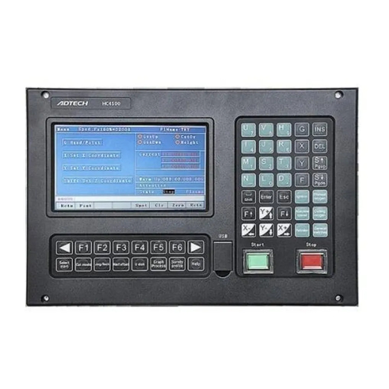
Flame / Plasma Cutting Machine CNC System
User's Manual
Adtech (Shenzhen) CNC Technology Co., Ltd.
Add: F/5, Bldg/27-29, Tianxia IC Industrial Park, Yiyuan Rd, Nanshan District, Shenzhen
Postal code: 518052
Tel: 0755-26722719 (20 lines)
Fax: 0755-26722718
E-mail: Adtech@21cn.com
http://www.adtechcn.com
Advertisement
Table of Contents

Summary of Contents for Adtech ADT-HC4500
- Page 1 Flame / Plasma Cutting Machine CNC System User’s Manual Adtech (Shenzhen) CNC Technology Co., Ltd. Add: F/5, Bldg/27-29, Tianxia IC Industrial Park, Yiyuan Rd, Nanshan District, Shenzhen Postal code: 518052 Tel: 0755-26722719 (20 lines) Fax: 0755-26722718 E-mail: Adtech@21cn.com http://www.adtechcn.com...
- Page 2 This manual doesn’t contain any assurance, stance or implication in any form. Adtech and the employees are not responsible for any direct or indirect data disclosure, profits loss or cause termination caused by this manual or any information about mentioned products in this manual.
- Page 3 ADT-HC4500 Flame/Plasma Cutting Machine CNC System Basic Manual Info Item No. First uploaded on Version No. Pages Compiled by Typeset by XT20110101 2010/03/07 A0101 Xiaodan Xiaodan Revision Date Version/Page Result Confirmed by - 2 -...
- Page 4 ADT-HC4500 Flame/Plasma Cutting Machine CNC System Precautions Transportation and storage The packaging boxes shouldn’t be stacked more than six layers Do not climb onto, stand on or put heavy objects on the packaging box Do not drag or convey the product with a cable connected to the product...
-
Page 5: Table Of Contents
ADT-HC4500 Flame/Plasma Cutting Machine CNC System Contents Chapter I: Introduction ..................... - 7 - 1. Function ..............................- 7 - 2. Features ..............................- 7 - 3. Application environment ........................... - 8 - Chapter II: Quick Guide ....................- 9 - 1. - Page 6 ADT-HC4500 Flame/Plasma Cutting Machine CNC System 5. Diagnosis ..............................- 75 - 5.1 Submenu description ........................- 75 - 6. Upgrade ..............................- 79 - 6.1 Submenu description ........................- 79 - 6.2 Reset .............................. - 80 - 6.3 Upgrading through USB disk ......................- 83 - 6.4 Connecting to PC and upgrading ....................
- Page 7 ADT-HC4500 Flame/Plasma Cutting Machine CNC System 2. The cutting isn’t accurate ........................- 122 - 3. The cutting quality of corners is low ..................... - 122 - 4. The cut square becomes rectangle ......................- 122 - 5. The cut circle becomes ellipse ....................... - 122 - 6.
-
Page 8: Chapter I: Introduction
IC chip and multilayer PCB. The monitor is 7” color display, and uses SMT process. The hardware of this controller bases on the powerful R&D strength of Adtech for many years, and the software integrates features of many domestic and foreign manufacturers. This controller features high hardware stability, perfect and mature software performance. -
Page 9: Application Environment
ADT-HC4500 Flame/Plasma Cutting Machine CNC System 14) Space running, board measuring, knife aligning, and backtracking 15) Slot compensation, backlash compensation for machine tools 16) Graphics display, real-time cutting track display 17) Integrate diagnosis function to help users eliminate machine failures quickly... -
Page 10: Chapter Ii: Quick Guide
ADT-HC4500 Flame/Plasma Cutting Machine CNC System Chapter II: Quick Guide ADT-HC4500 flame/plasma CNC cutting system controls the flame or plasma torch for cutting on the machine tool. The system displays in progressive windows. In certain interface, you can press [F1] to [F6] to select a function, and press [ ] or [ ] to return to previous menu. -
Page 11: Get Help Info
ADT-HC4500 Flame/Plasma Cutting Machine CNC System Press [F6] to enter system parameter reset, software update and help interface. 1. Get help info In most menus, you can press [INS] to get the help information; for example, press [F1] (Auto) in the main menu to enter the Auto interface, and then press [INS] to get the help info about the Auto interface. -
Page 12: Graphics Library
ADT-HC4500 Flame/Plasma Cutting Machine CNC System 3. Graphics library To facilitate the processing, reduce the workload and increase system usability, the system embodies 35 common processing part graphics and one test graphics. In the main menu interface, press [F2] (Graphics library) to enter the graphics library interface, and select the corresponding graphics parts in the library to process. -
Page 13: Importing Processing File
ADT-HC4500 Flame/Plasma Cutting Machine CNC System Current directory: Return / New / Copy Delete Return Fig. 2.4 Copy Processing Files Then, press [Y+][Y-] to select the processing file to copy, and press [F2] (Copy) or [OK] to copy; after copying, press any key to return to the main menu when the prompt pops up. -
Page 14: Adjusting Cutting Speed
ADT-HC4500 Flame/Plasma Cutting Machine CNC System Return Import Delete / Copy / Copy all / Return Fig. 2.5 File Importing Interface In above interface, press [Y+][Y-] to select a processing file and then press [F2] or [OK] to confirm; the system enters processing code edit interface. - Page 15 ADT-HC4500 Flame/Plasma Cutting Machine CNC System Manual speed Processing speed Return / System / Speed / Adjust / Control / Precision / Store / Return 2.6.1 Speed Setting Interface Press [X+], [X-], [Y+], [Y-] to move the cursor to select, and press the number keys in the left to enter the value.
-
Page 16: Adjusting Manual Speed
ADT-HC4500 Flame/Plasma Cutting Machine CNC System The processing speed depends on the “Processing speed limit” in Speed Setting interface and “Speed percentage” in Auto interface. Actual processing speed = Processing speed × Speed percentage in Auto interface Note: The speed percentage is adjusted with [F ]/[F ] on the panel or the [F] key. -
Page 17: Controlling Corner Cutting Quality
ADT-HC4500 Flame/Plasma Cutting Machine CNC System Note: The speed percentage is adjusted with [F ]/[F ] on the panel or the [F] key. 8. Controlling corner cutting quality During flame cutting and plasma cutting, the speed should be controlled when cutting the corners. The acceleration/deceleration setting directly affects the quality of corner cutting, especially during the flame cutting, if the speed is too high, the flame may be off or can’t cut through the steel plate;... - Page 18 ADT-HC4500 Flame/Plasma Cutting Machine CNC System data are adjusted according to field cutting effect: Processing speed (mm/min) Start speed (mm/min) 100-200 200-500 500-700 700-800 800-1000 1000-1300 1600-2000 1000 2000-3000 1500 3000-4000 2000 Table 2.8.1 Acceleration: the average increment that the processing speed is added from start speed to top speed;...
-
Page 19: Adjusting Preheating Time While Flame Cutting
ADT-HC4500 Flame/Plasma Cutting Machine CNC System 0.010000-0.011000 0.011000-0.012000 0.012000-0.013000 Table 2.8.2 9. Adjusting preheating time while flame cutting In the main menu interface, press [F4] (Parameter) [F4] (Control), and set the “Preheating delay” in the second line to desired time. - Page 20 ADT-HC4500 Flame/Plasma Cutting Machine CNC System Return 2.9.1 Control Interface While cutting in Auto interface, the system performs preheating before perforation. At this moment, the lower right of the interface shows the total preheating time and preheated time. In the bottom center, the system prompts: “To memorize and stop preheating, press [G];...
-
Page 21: Power Failure Treatment
ADT-HC4500 Flame/Plasma Cutting Machine CNC System Prompt: Working state: Running Flame Return / Demonstrate / Manual / Back / Process / Return reference / Break point / Return 2.9.2 Auto Interface Preheating 10. Power failure treatment To avoid material waste caused by sudden power failure, the system integrates power failure protection function. -
Page 22: Shift And Punch
ADT-HC4500 Flame/Plasma Cutting Machine CNC System Auto Speed: / Program name Prompt: Cut after idle stroke return Stop after idle stroke return Cut and return directly Continue at current position Torch up / Cutting Control Torch down / Height control... -
Page 23: Moving Workpiece
ADT-HC4500 Flame/Plasma Cutting Machine CNC System Fig. 1 Fig. 2 As in Fig. 1, the outer rectangle is steel plate and the inner rectangle is the workpiece to be cut. Suppose cutting from point A, if the steel plate being processed if too thick, it requires rather long time for perforating; however, it will save the preheating time to cut from point B, i.e. -
Page 24: Array
ADT-HC4500 Flame/Plasma Cutting Machine CNC System Current state: Turning / Program name: Please select the positioning mode for line selecting: 1Current point 2Origin Press OK after selecting Please enter the target line No.: Return / Turn / Select line /... - Page 25 ADT-HC4500 Flame/Plasma Cutting Machine CNC System Current state : Array Program name: Please enter the parameters: 1Line No. 2Row No. 3 Line space 4Row space 5Plate width 6Plate height X. Vertical Y. Staggered Width: Height: Return / Turn / Select line /...
- Page 26 ADT-HC4500 Flame/Plasma Cutting Machine CNC System Current state: Array Program name Please enter the parameters: 1 Line No. 2Row No. 3Line space 4Row space 5Plate width 6Plate height Select array direction and then press [OK] Width: Height: Return / Turn /...
-
Page 27: Mirror
ADT-HC4500 Flame/Plasma Cutting Machine CNC System Current state: Array Program name Please enter the parameters: 1Line No. 2Row No. 3 Line space 4Row space 5Plate width 6Plate height X. Vertical Y. Staggered Return / Turn / Select line / Select point /... - Page 28 ADT-HC4500 Flame/Plasma Cutting Machine CNC System press [F1] (X mirror) or [F2] (Y mirror) or [F3] (XY mirror), as in the figure below: Current state: Turn Program name Current graphics size Height Width Return /X X mirror / Y Y mirror/ XY...
-
Page 29: Rotate
ADT-HC4500 Flame/Plasma Cutting Machine CNC System Height Width Return / X X mirror /Y Y mirror/XY XY mirror / Rotate / Correct / Restore / Return Fig. 2.17.2 After X Mirror 18. Rotate While cutting, the position and angle of steel plate should coincide with XY axis of the cutter; during the actual processing, offset is inevitable, and XY axis on the steel plate shifts the moving angle relative to the XY axis of the machine tool. -
Page 30: Correct
ADT-HC4500 Flame/Plasma Cutting Machine CNC System 19. Correct If the rotation angle isn’t determined while correcting, we can get the rotation angle through the correction function. First, a reference axis is required for correction, and the graphics rotate for certain angle around this axis. - Page 31 ADT-HC4500 Flame/Plasma Cutting Machine CNC System plate and axis X of reference coordinates. If axis Y is the reference axis: the offset angle of the steel plate is the angle between axis Y of the steel plate and axis Y of reference coordinates.
- Page 32 ADT-HC4500 Flame/Plasma Cutting Machine CNC System Fig. 1 Fig. 2 1) In Fig. 1 above, the bigger frame (real line) is the steel plate, the smaller frame (broken line) is the graphics to be cut, and point A is the start position of the torch. If cutting according to the position in Fig.
-
Page 33: Selecting Cutter Point
ADT-HC4500 Flame/Plasma Cutting Machine CNC System relationship between the graphics to be processed and the steel plate follows: 3) If the steel plate inclines to the left as in the figure below, the correcting method follows: Original position of torch Position after moving Press [X+] and then press [Y+], or press [Y+] and then [X+], and then press [OK]. - Page 34 ADT-HC4500 Flame/Plasma Cutting Machine CNC System In pause state, press [G], and the start point moves to the lower left of the graphics automatically; press [G] again, and the start point moves to the lower right. Press it repeatedly, and the start point appears in the four corners of the graphics in sequence.
-
Page 35: Chapter Iii: Detailed System Operation And Instructions
ADT-HC4500 Flame/Plasma Cutting Machine CNC System Chapter III: Detailed System Operation and Instructions 1. Auto In the main menu interface, press [F1] (Auto) to enter automatic processing interface, as shown below: Auto Speed: Program name Ethyne control / Torch up... - Page 36 ADT-HC4500 Flame/Plasma Cutting Machine CNC System Auto Speed: Program name: GLOBAL Torch up / Cutting Control Torch down / Height control Current coordinates Slot compensation Prompt: Working state: Stopped Plasma Return / Demonstrate / Manual / Back / Process /...
-
Page 37: Program Running Description
ADT-HC4500 Flame/Plasma Cutting Machine CNC System Current function, mode and state of the system; Cutter model; Current working state of the system; Code run by current processing program; Tracking of current processing graphics; The differences between plasma and flame processing interface are that plasma doesn’t have preheating time and certain electronic valves are different. - Page 38 ADT-HC4500 Flame/Plasma Cutting Machine CNC System Slot compensation Prompt: Working state: Paused Plasma Return / Demonstrate / Manual / forward/ Back / Process / Return reference / Break point / Return Fig. 3.1.1 Pause during Automatic Processing Treatment while pause (shift perforating and torch replacing function):...
-
Page 39: Submenu Description Of Auto Interface
ADT-HC4500 Flame/Plasma Cutting Machine CNC System Return / Demonstrate / Manual / Back / Process / Return reference / Break point / Return Fig. 3.1.1.2 Pause Treatment While cutting, if you press [Pause], the following treatment is available according to whether the torch is moved manually: 1) If the torch isn’t moved manually after pause, you can press the [Start] button directly to make... - Page 40 ADT-HC4500 Flame/Plasma Cutting Machine CNC System 1.2.2 Manual In the main menu, press [F1] (Auto) [F2] (Manual) to enter Manual interface: Manual Speed: Program name: G: switch Manual/Jog Ethyne control / Torch up X: Set coordinates of X axis Preheating control /...
- Page 41 ADT-HC4500 Flame/Plasma Cutting Machine CNC System Manual Speed: Program name: G: switch Manual/Jog Torch up / Cutting Control X: Set coordinates of X axis Torch down/ Height control Y: Set coordinates of Y axis Current coordinates: Shift Shift: Set coordinates of Z axis...
- Page 42 ADT-HC4500 Flame/Plasma Cutting Machine CNC System 1.2.2.1 Jog Manual Speed: Program name: G: switch Manual/Jog Ethyne control / Torch up X: Set coordinates of X axis Preheating control / Torch down Y: Set coordinates of Y axis Cutting Control /...
- Page 43 ADT-HC4500 Flame/Plasma Cutting Machine CNC System [X-], [Y+], [Y-], the respective axis performs continuous motion; when you release [X+], [X-], [Y+], [Y-], the system will decelerate and stop motion. 1.2.2.2 Breaking point Manual Speed: Program name: G: switch Manual/Jog Ethyne control /...
- Page 44 ADT-HC4500 Flame/Plasma Cutting Machine CNC System 1.2.2.3 Clear In the manual interface, press [F5] to clear the parameters in memory; if you press [X] or [Y] [F5] (Clear) [OK], the X, Y coordinates of the entire line will be cleared; to clear the last digit only, press [DEL] on the panel.
- Page 45 ADT-HC4500 Flame/Plasma Cutting Machine CNC System the figure below Please select corresponding graphics processing function Program name Current graphics size Width Height Return / Turn / Select line / Select point / Array / Restore / Return Fig. 3.1.2.5.1 Graphics Processing Interface 1.2.5.1.1 Turn...
- Page 46 ADT-HC4500 Flame/Plasma Cutting Machine CNC System Current state: Turn Program name Current graphics size Height Width Return / X X mirror /Y Y mirror /XY XY mirror / Rotate / Correct / Restore / Return Fig. 3.1.2.5.1.1 Graphics Processing Interface 1.2.5.1.2 X/Y mirror...
- Page 47 ADT-HC4500 Flame/Plasma Cutting Machine CNC System 1.2.5.1.7 Selecting point In the processing interface shown in Fig. 3.1.2.5.1, press [F3] (Select point) to enter point selecting. Current state: Select point / Current point: Program name Please select the point selecting mode...
- Page 48 ADT-HC4500 Flame/Plasma Cutting Machine CNC System 1.2.5.1.8 Array Please refer to Chapter II Section 16: Array. 1.2.5.1.9 Restore In processing and turn interface, press [F6] (Restore) to restore the graphics after array, selecting point and line to the graphics before being imported.
-
Page 49: Basic Operation
ADT-HC4500 Flame/Plasma Cutting Machine CNC System Current coordinates: Slot compensation: Preheating delay: Prompt: Start from power failure memory Working state: Stopped Flame Return / Demonstrate / Manual/ back / process / Return reference / Break point / Return 3.1.2.7 Start from Power Failure Memory If the automatic processing is paused manually, press [F6] (Break point), and the system will save current track (torch position) as a break point automatically. -
Page 50: Graphics Library
ADT-HC4500 Flame/Plasma Cutting Machine CNC System hold this key to increase or decrease the speed continuously; if during processing, press the key to increase or decrease the speed percentage by 1 every time. Press [Pgup/S ] and [Pgdn/S ], which are composite key. Press [Pgup/S ] (or [Pgdn/S ]) to move the torch upwards (or downwards);... - Page 51 ADT-HC4500 Flame/Plasma Cutting Machine CNC System Fig. 2.1 We will take “Circle” as an example for description. Move the blue frame to the circle and press [OK] to enter the graphics. Graphics Library Parameters Settings Part type: piece Radius Lead-in wire...
-
Page 52: Edit
ADT-HC4500 Flame/Plasma Cutting Machine CNC System The parameter settings of the graphics library are limited: the circle radius shouldn’t exceed the radius of outer arc, or the height from circle center to base side of the trapezium; base side length of the trapezium shouldn’t be smaller than two times of top arc radius. -
Page 53: Submenu Description
ADT-HC4500 Flame/Plasma Cutting Machine CNC System 3.1 Submenu description 3.1.1 New Input method: Please type the file name: Return / Save / Return Fig. 3.1.1 New File Interface In Fig. 3.1 edit interface, press [F1] to enter new file interface as shown in Fig. 3.1.1. At this moment, you can press the number keys directly to edit the file name, and press [F5] to save, or press [shift] to switch the input method. - Page 54 ADT-HC4500 Flame/Plasma Cutting Machine CNC System Delete Switch input method / OK / Cancel Page-up / Down / Page-down After entering, press [OK]; if the file name already exists in the system, press [OK], and the system will prompt, as shown in Fig. 3.1.1.2 below, or else enter the file edit interface, as in Fig. 3.1.1.3;...
- Page 55 ADT-HC4500 Flame/Plasma Cutting Machine CNC System Input method: Prompt The file exists. Overwrite? Cancel Return / Save / Return Fig. 3.1.1.2 File Name Already Exists in the System In this prompt interface, press [OK] to overwrite the original file and enter the interface shown in Fig.
- Page 56 ADT-HC4500 Flame/Plasma Cutting Machine CNC System Current directory: Name / Size (byte) / Type Return / Import / Delete / Copy / Copy all / Return Fig. 3.1.2 File Importing Interface In above interface, press [F ][F ] to select a processing file, and then press [F2] or [OK] to select, and then enter the processing code edit interface.
- Page 57 ADT-HC4500 Flame/Plasma Cutting Machine CNC System Current directory: Copying data. Please wait…… Return / New / Copy / Delete / Return Fig. 3.1.2.1 File Copy Function 3.1.2.2 Delete In processing file importing interface, you can select to delete the files in system directory. The system will ask you to confirm, you can press [OK] --- Delete;...
- Page 58 ADT-HC4500 Flame/Plasma Cutting Machine CNC System Prompt Delete this file? Cancel Return / Import / Delete / Copy / Copy all / Return Fig. 3.1.2.2 Delete Interface 3.1.3 USB disk In Fig. 3.1 Edit Menu Option Window, press [F3] to enter USB connection. If the USB disk isn’t connected...
- Page 59 ADT-HC4500 Flame/Plasma Cutting Machine CNC System Current directory: Return / New / Copy / Delete / Return Fig. 3.1.3.1 USB disk is connected successfully Press [Y+][Y-] to select the processing file to copy, and then press [F2] (Copy) or [OK]. After that, the system will prompt “Copy data successfully.
- Page 60 ADT-HC4500 Flame/Plasma Cutting Machine CNC System Flame: Fixed ignition cycle Fixed torch down cycle Fixed preheating cycle Fixed perforating torch up cycle Cutting oxygen on Fixed perforating torch down cycle Plasma: A. When height adjustment system is integrated: Height adjustment on M22...
-
Page 61: Editing Processing Files
ADT-HC4500 Flame/Plasma Cutting Machine CNC System 3.2 Editing processing files In Fig. 3.1 Edit Menu Option Window, if you create a new file or import a file successfully, the system will enter the edit interface automatically, and then you can edit the processing file, as shown below:... - Page 62 ADT-HC4500 Flame/Plasma Cutting Machine CNC System Encoding completes. Code entered correctly. Return / Graphics / Test / Save / Add line / Delete line / Return Fig. 3.2.1.2 Code Error Check Interface If the check code has error, the cursor will stay in the line with error. You can press [OK] to modify the error, and then press [F2] to check the processing file.
-
Page 63: Basic Operation
ADT-HC4500 Flame/Plasma Cutting Machine CNC System In above interface, press [OK] to re-check from the first line, or press [Cancel] to check from the cursor. 3.2.3 Save Prompt Save in another file name? Press OK to save, or press Cancel to exit... -
Page 64: Parameters
ADT-HC4500 Flame/Plasma Cutting Machine CNC System press it to execute the lower functions on the keys, or press [Shift] and the composite keys to execute the upper functions. This function is only available in program edit state. When cursor moves up/down, you can locate the cursor at the line end of the program automatically, and press to move the cursor for one line every time. - Page 65 ADT-HC4500 Flame/Plasma Cutting Machine CNC System System Configuration Interface M07 instruction: Default M08 instruction: Default Model: Flame System: Metric Language: Chinese Return / Configure / Adjust height / Advance / Flame / Save / Return Fig. 4.1 Configuration Interface M07, M08 instruction: The user can select Default or Custom for M07, M08 preheating perforating instruction.
- Page 66 ADT-HC4500 Flame/Plasma Cutting Machine CNC System Plasma Height Adjustment Interface Allow height adjustment: Initial positioning: Arc voltage test Return / Configure / Adjust height / Advance / Flame / Save / Return Fig. 4.1.1 Height Adjustment Allow height adjustment: When the system is installed with arc voltage height adjustment device, this controls when to turn on/off arc voltage height adjustment.
- Page 67 ADT-HC4500 Flame/Plasma Cutting Machine CNC System Flame Step Height Adjustment Setting Allow Z axis height adjustment: Off Z axis pulse equivalent Z axis start speed Z axis acceleration Z axis maximum speed: Torch up/down distance Perforating up/down distance: Return /...
-
Page 68: Speed
ADT-HC4500 Flame/Plasma Cutting Machine CNC System 7) Perforating up/down distance: the distance that torch rises from cutting height to safe height while perforating (the distance that torch rises from safe height to cutting height), preventing high temperature solution entering the nozzle. -
Page 69: Adjustment
ADT-HC4500 Flame/Plasma Cutting Machine CNC System 4.2.1 Speed setting Parameter Description Unit Start speed Start speed of axis X/Y mm/min Acceleration The speed value of axis X/Y added every time from start speed to mm/min maximum speed Manual speed Axis X/Y speed during manual running, G00 and reference returning... - Page 70 ADT-HC4500 Flame/Plasma Cutting Machine CNC System Parameter Setting Interface Soft positive limit Soft negative limit Machine tool origin Reverse clearance Return / System / Speed / Adjust / Control / Precision / Store / Return Fig. 4.3Parameter Setting Interface 4.3.1 Adjustment setting...
-
Page 71: Control
ADT-HC4500 Flame/Plasma Cutting Machine CNC System Reverse Clearance compensation for axis Y during reverse direction clearance (Y) change Table 4.3.1 4.4 Control In Fig. 4 system parameter setting interface, press [F4] to show the interface below, in which you can set X, Y motor speed, preheating and torch up/down time during automatic processing. - Page 72 ADT-HC4500 Flame/Plasma Cutting Machine CNC System Plasma Control Parameter Interface Start arc delay Torch up delay Torch down delay Preheating delay Corner speed ratio Positioning up time Slot compensation Preheating up delay Corner arc radius Corner down speed Return /...
- Page 73 ADT-HC4500 Flame/Plasma Cutting Machine CNC System can be adjusted Torch up delay Used before G00 transferring position to raise the torch to 0.01 sec an appropriate height, preventing the torch and steel plate from colliding Torch down Counter action of torch up delay lowers the torch to an 0.01 sec...
-
Page 74: Precision
ADT-HC4500 Flame/Plasma Cutting Machine CNC System Slot Flame/plasma radius compensation compensation Preheating up (Plasma) Torch up time while perforating delay 0.01 sec delay Corner speed (Plasma) When the processing speed percentage drops to ratio this value, height adjustment control signal is turned off;... - Page 75 ADT-HC4500 Flame/Plasma Cutting Machine CNC System Pulse Equivalent Setting Interface X axis pulse equivalent Y axis pulse equivalent Note: The unit is N·mm/min. Return / System / Speed / Adjust / Control / Precision / Store / Return Fig. 4.5 Precision Parameter Interface 4.5.1 Pulse equivalent settings...
-
Page 76: Storage
ADT-HC4500 Flame/Plasma Cutting Machine CNC System 1) Return to the main interface, press [F4] and then [F5] to enter precision setting interface, enter 0.005780 into X, Y axis pulse equivalent coefficient. Note: Generally, the pulse equivalent of X, Y axis has a little error. Please set respectively. - Page 77 ADT-HC4500 Flame/Plasma Cutting Machine CNC System Press [F4] to test the reverse rotation of X axis Press [F5] to stop current rotation of X/Y axis Press [X+] [X-] [Y+] [Y-] to move output cursor, and press [OK] to output related switching signal.
- Page 78 ADT-HC4500 Flame/Plasma Cutting Machine CNC System Select the output port to set Ignition control: Default Preheating oxygen control: Default Ethyne control: Default Cutting oxygen control: Default Torch up control: Default Torch down control: Default Return Return Flame - 77 -...
- Page 79 ADT-HC4500 Flame/Plasma Cutting Machine CNC System Select the output port to set Start arc control: Default Corner control: Default Perforating torch up control: Default Perforating torch down control: Default Return Return Plasma Fig. 5.1.2 Customizing Output Port 4) In the Diagnosis interface shown in Fig. 5, press [F5] to show the latest update of the system.
-
Page 80: Upgrade
ADT-HC4500 Flame/Plasma Cutting Machine CNC System 6. Upgrade This function is used by the used to upgrade the software. In the main interface, press [F6] to enter the upgrade option window, as shown in Fig. 6: Upgrade Interface (F1) System parameter reset... -
Page 81: Reset
ADT-HC4500 Flame/Plasma Cutting Machine CNC System 6.2 Reset In Fig. 6.1 Upgrade Interface, press [F1] to enter system parameter reset/save interface. Reset (F1) Reset current parameters to default (F2) Set current parameters to default Back / Reset / Save Back Fig. - Page 82 ADT-HC4500 Flame/Plasma Cutting Machine CNC System Prompt Reset current parameters to default? Cancel Return / Reset / Save / Return Fig. 6.2.2 Can’t reset the parameters Prompt Reset parameters successfully. Please restart. Return / Reset / Save / Return Fig. 6.2.3 Reset parameters successfully...
- Page 83 ADT-HC4500 Flame/Plasma Cutting Machine CNC System In system parameter reset/save interface, you need to enter the valid password to save the parameters; if you don’t want to save, press [ ] or [ ] to return. Prompt Please type the password...
-
Page 84: Upgrading Through Usb Disk
ADT-HC4500 Flame/Plasma Cutting Machine CNC System Prompt Set current parameters as default? Cancel Return / Reset / Save / Return Fig. 6.2.5 Default Setting Prompt Interface In Default Setting Prompt Interface, press [OK] to set current parameters as default, and the parameters will be reset to this default value. - Page 85 ADT-HC4500 Flame/Plasma Cutting Machine CNC System Current directory Can’t find USB disk. Press any key to return Return / New / Copy / Delete / Return Fig. 6.3.1 USB disk isn’t connected successfully Copy the latest program to USB disk, and insert the disk into USB interface. In the main interface, press [F6] to enter the upgrade interface, and press [F2] to show the interface in Fig.
- Page 86 ADT-HC4500 Flame/Plasma Cutting Machine CNC System Current directory Multiple copies copy copy Return / Reset /U USB disk / Restart / PC / Help / Return Fig. 6.3.2 USB disk is connected successfully If the USB disk is connected successfully, press [Y+], [Y-] in the directory to move cursor to “2440TEST.BIN”...
- Page 87 ADT-HC4500 Flame/Plasma Cutting Machine CNC System Current directory This isn’t system file. Upgrade fails Return / Reset /U USB disk / Restart / PC / Help / Return Fig. 6.3.4 Upgrade fails If the selected file is appropriate, the interface after downloading the program is shown below:...
-
Page 88: Connecting To Pc And Upgrading
ADT-HC4500 Flame/Plasma Cutting Machine CNC System update interface and burn the latest program into BIOS chip. Return / Restart / OK / Return Fig. 6.3.5 Upgrade completes At this moment, press [F3] to restart, press [Cancel] after one second to enter the interface shown in Fig. -
Page 89: Burning Program
ADT-HC4500 Flame/Plasma Cutting Machine CNC System [Cancel] and connect the power to burn the latest program into BIOS chip. Refer to 6.6 for specific operation. Fig. 6.5.1.1 USB cable 6.5 Burning program After transmitting the latest software to the controller, you need to save the software in the BIOS of the controller, making the controller be able to execute the latest software. - Page 90 ADT-HC4500 Flame/Plasma Cutting Machine CNC System Current date: January 13, 2006; Current time: 11:00:00 0 – System setting 0---- 1 – BIOS setting 1----BIOS 2 – USB disk setting 2---U 3 – System self test 3--- 4 – Start mode 4--- 5 –...
-
Page 91: Bios Interface Connecting To Pc And Upgrading
ADT-HC4500 Flame/Plasma Cutting Machine CNC System and the system will find the file to update, and prompt “NAND Flash programming completes” after that. Please cut off the power supply and restart the controller. After updating the program, check whether the start mode is “Normal”, as shown below: Current date: January 13, 2006;... - Page 92 ADT-HC4500 Flame/Plasma Cutting Machine CNC System Current date: January 13, 2006; Current time: 11:00:00 0---- 0 – System setting 1---BIOS 1 – BIOS setting 2---U 2 – USB disk setting 3---- 3 – System self test 4---- 4 – Start mode 5---- 5 –...
- Page 93 ADT-HC4500 Flame/Plasma Cutting Machine CNC System Current date: January 13, 2006; Current time: 11:00:00 0----USB 0 – USB communication 1---- 1 – Format USB disk 2---U 2 – Copy data in USB disk 3---- YAFFS2 3 – Format YAFFS2 section...
-
Page 94: Help System
ADT-HC4500 Flame/Plasma Cutting Machine CNC System Current date: January 13, 2006; Current time: 11:00:00 Please select the section to update: 0----BIOS 0 – BIOS section 1--- 1 – Program section 2----16 2 – 16-dot matrix section 3----24 3 – 24-dot matrix section Press number keys to perform operations, press [ESC] to return 6.6.6 Entering setting interface of BIOS... -
Page 95: Using Different Languages
ADT-HC4500 Flame/Plasma Cutting Machine CNC System the entire help file. Note: The help involves G code, M code and commonly used instructions that are easily to be forgotten. 3) Press [pgup ] [pgdn ] to turn pages, and press [ ] or [ ] to exit the help system and return to current interface. - Page 96 7. If the equal mark isn’t followed by any content, which is preserved length of previous line, you can write the excessive part of previous line after translated. For example: (Chinese info) [1]=Adtech (Shenzhen) CNC Technology Co., Ltd.; ( 60 Byte) [2]=; [3]= …;...
-
Page 97: Chapter Iv: Instruction Programming System
ADT-HC4500 Flame/Plasma Cutting Machine CNC System Chapter IV: Instruction Programming System 1. Description of programming symbols Every motion of the CNC processing follows specified procedure, every processing program consists of several instructions, every instruction consists of several function words, and every function word is started with letter and followed by parameter value. -
Page 98: Absolute Coordinates
ADT-HC4500 Flame/Plasma Cutting Machine CNC System Fig. 2.1 As in the figure above, if calculated with relative coordinates, the coordinates of the entire graphics will be: 1. A is the origin, and the coordinates are X0, Y0; 2. B relative to A: X50, Y50;... -
Page 99: G92 Reference Point Setting
ADT-HC4500 Flame/Plasma Cutting Machine CNC System 3.1. G92 reference point setting When setting program running, the coordinates of processing start (reference point) must be put at the start of the program. Format: G92 X0 Y0 If G92 isn’t followed by X, Y, the current coordinates of X, Y will be the reference point. Generally, if the origin of machine tool is used for positioning, G92 won’t be followed by X, Y. -
Page 100: G02/G03 Arc Cutting
ADT-HC4500 Flame/Plasma Cutting Machine CNC System G92 X0 Y0 G00 X100 Y50 G01 X30 Y90 Current position of torch Expected position of torch 3.5. G02/G03 arc cutting This instruction is used to cut a circle or arc, while circles include G02 (clockwise) and G03 (counterclockwise) -
Page 101: G26, G27, G28 Returning To Reference Point
ADT-HC4500 Flame/Plasma Cutting Machine CNC System If G04 isn’t followed by Ln, the system will be delayed without day after executing G04 until you press [Start] to stop the delay. 3.7. G26, G27, G28 returning to reference point This instruction can return the torch to reference point automatically. The processing is at run idle speed, i.e. -
Page 102: G91/G90 Relative/Absolute Coordinate Programming
ADT-HC4500 Flame/Plasma Cutting Machine CNC System 0005: M02 3.10. G91/G90 relative/absolute coordinate programming Relative coordinates under G91 (default), absolute coordinates under G90 Format: G91 G01 X100 3.11. G41/G42/G40 Set the slot compensation, which is set before steel plate perforating and cutting, and canceled by M08 instruction... - Page 103 ADT-HC4500 Flame/Plasma Cutting Machine CNC System 2. Start arc M12 3. Wait for arc voltage test signal (IN0) When arc starts, the height adjuster initializes the positioning automatically (height adjuster with initial positioning, which is disabled in parameters); perforates, delays, and sends a successful arc voltage test signal to the controller.
- Page 104 ADT-HC4500 Flame/Plasma Cutting Machine CNC System Fixed preheating cycle (controlled by time in “Control” interface) General switch; all outputs will be turned off after performing M80 - 103 -...
-
Page 105: Chapter V: Hardware
ADT-HC4500 Flame/Plasma Cutting Machine CNC System Chapter V: Hardware 1. Dimensions Fig. 1.1 Front Appearance Dimensions Fig. 2.1 Side Appearance Dimensions - 104 -... -
Page 106: System I/O Connection
ADT-HC4500 Flame/Plasma Cutting Machine CNC System Digital output Motor Digital input USB communication / Serial port Fig. 2.1 Rear Appearance Dimensions Note: The length above is in “mm”; 2. System I/O connection 2.1 Rear cover view Digital output Motor - 105 -... -
Page 107: Electrical Specifications
ADT-HC4500 Flame/Plasma Cutting Machine CNC System Digital input USB communication / Serial port 2.2 Electrical specifications Switching quantity input Channel: 32, all optic coupling isolation Input voltage: 12-24V DC High level>4.5V Low level<1.0V Isolation voltage: 2500V DC Count input: Channel: main axis ABZ phase code input, all optic coupling isolation... -
Page 108: Electrical Connection
ADT-HC4500 Flame/Plasma Cutting Machine CNC System 2.3 Electrical connection 2.2.1 Motor control interface——15-port socket (male) XDR+ XDR- XPU+ XPU- YDR+ YDR- YPU+ YPU- ZDR+ ZDR- ZPU+ ZPU- PU_COM Wire No. Definition Fun ctio n XDR+ X direction signal + XDR-... - Page 109 ADT-HC4500 Flame/Plasma Cutting Machine CNC System supply Negative end of internal 5V power supply; can’t connect to external power supply Wiring mode of pulse output signal: Æ Differential mode: This mode is recommended for step drives with independent pulse and direction input and most servo drives to get better anti-interference.
- Page 110 ADT-HC4500 Flame/Plasma Cutting Machine CNC System in differential mode, PU_COM and 5V- do not need to be connected. Please note that PU_COM shouldn’t be used for any other purpose except non-differential connection of drive pulse, or else the controller may be damaged.
- Page 111 ADT-HC4500 Flame/Plasma Cutting Machine CNC System Internal 24V+ of the controller (do not connect any circuit) +24V Internal 24V+ of the controller (do not connect any circuit) +24V Internal 24V+ grounding of the controller IN10 Y axis positive limit (>Y+) IN11 Y axis negative limit (Y-<)
- Page 112 ADT-HC4500 Flame/Plasma Cutting Machine CNC System 2.2.3 Output control interface——25-port socket (female) Wire No. Definition Fun ctio n OUT0 Flame cutting ethyne valve control, M10 (ON), M11 (OFF) OUT1 Torch up control, M14 (ON), M15 (OFF) OUT2 Flame cutting ignition control, M20 (ON), M21 (OFF)
- Page 113 ADT-HC4500 Flame/Plasma Cutting Machine CNC System Flame cutting preheating oxygen valve control, M24 (ON), M25 (OFF) OUT11 Reserved preheating oxygen control, M26 (ON), M27 (OFF) OUT12 Reserved cutting oxygen/start arc control, M32 (ON), M33 (OFF) OUT13 Reserved torch down control, M36 (ON), M37 (OFF)
- Page 114 ADT-HC4500 Flame/Plasma Cutting Machine CNC System 2.2.4 Serial communication interface—— 9-port socket (male) Wire No. Definition Fun ctio n Null Transmit data (dedicated fo r software engineer) Receive data (dedicated for so ftware engineer) Null Grounding Null Null Null Null...
-
Page 115: Motor Connection
ADT-HC4500 Flame/Plasma Cutting Machine CNC System 2.2.5 Power connection of SX8 2.2.6 Standard USB interface of SX11 3. Motor connection 3.1 Differential drive connection The following diagram is the controller connected to ADT Q2BYG404MA drive: Q2BYG404MA drive Controller XS3 plug... - Page 116 ADT-HC4500 Flame/Plasma Cutting Machine CNC System Q2BYG404MA drive 5V motor locked DC power 18-40V DC power Blac 56BYGH630C Step motor Blue Yell The following diagram is ADT Q2BYG404MA drive connected to 56BYGH630EJP step motor - 115 -...
- Page 117 ADT-HC4500 Flame/Plasma Cutting Machine CNC System Q2BYG404MA drive 5V motor locked DC power 18-40V DC power Blac Yell 56BYGH630EJP Step motor Oran Coffee The following diagram is ADT Q2BYG404MA drive connected to 85BYGH830A step motor - 116 -...
-
Page 118: Common Anode Drive Connection
ADT-HC4500 Flame/Plasma Cutting Machine CNC System Q2BYG404MA drive 5V motor locked DC power 18-40V DC power Yellow/blue Purple/brown 85BYGH830A Black Step motor White Green Remark: 1) Please adjust the drive subsections and current dip switch properly during operating. It is recommended to adjust the drive into 64 subsections, and adjust the current to 1.2 times of motor current. - Page 119 ADT-HC4500 Flame/Plasma Cutting Machine CNC System X axis drive XDR+ XDR- DIR+ XPU+ XPU- YDR+ OPTO YDR- Motor YPU+ locked YPU- power ZDR+ ZDR- ZPU+ power ZPU- PU_COM Step motor - 118 -...
-
Page 120: Panasonic Servo Drive Connection
ADT-HC4500 Flame/Plasma Cutting Machine CNC System 3.3 Panasonic servo drive connection Controller XS3 plug X axis drive XDR+ CN1/F5 SING1 XDR- CN1/F6 SING2 XPU+ CN1/F3 SING1 XPU- CN1/F4 SING2 YDR+ YDR- YPU+ YPU- ZDR+ ZDR- ZPU+ ZPU- PU_COM Servo motor 4. -
Page 121: Current Adjustment For The Drive
Please adjust the current according to the driver manual of the manufacturer. If you use the step motor drive Q2BYG404MA+56BYGH630C provided by Adtech, please adjust the drive current to 1.2 times of motor current. 4.3 Testing method of pulse equivalent Please refer to Chapter II —... - Page 122 ADT-HC4500 Flame/Plasma Cutting Machine CNC System Fig. 5.5.4 Note: Do not reel PE end i.e. earth wire into the magnetic ring. 3) A magnetic ring should be added to the end of X, Y axis signal output wire, as shown below:...
-
Page 123: Chapter Vi: Troubleshooting
ADT-HC4500 Flame/Plasma Cutting Machine CNC System Chapter VI: Troubleshooting 1. Can’t read USB disk A: Insert the USB disk into the controller, but the disk can’t be read. To solve this problem, you can modify the “File system” of USB disk with computer and then format the disk. The specific operation: insert the USB disk into the computer open “My Computer”... -
Page 124: The Motor Doesn't Work Or Is Similar To Crash In Auto Mode
ADT-HC4500 Flame/Plasma Cutting Machine CNC System 7. The motor doesn’t work or is similar to crash in auto mode A: Please check whether “Auto speed limit” is set to appropriate speed and whether the manual processing percentage is too low. - Page 125 ADT-HC4500 Flame/Plasma Cutting Machine CNC System 3) If the relay doesn’t have input voltage signal, the interior of output end of the CNC system is damaged. Please replace the reversed output according to the procedure below. 4) Open the case, and then open the output ports, as shown below:...
- Page 126 ADT-HC4500 Flame/Plasma Cutting Machine CNC System 7) After installation, connect the power supply of the system, press [F5] (Diagnosis) [F2] (Define) in the start-up interface, press [Y ], [Y ] to select up/down, press [X ], [X ] to select the state, and then press Save to change corresponding port to reserved.
-
Page 127: Appendix 2: Example Of Editing Processing Graphics
ADT-HC4500 Flame/Plasma Cutting Machine CNC System Appendix 2: Example of Editing Processing Graphics In the main interface, press [F3] to enter the edit interface, and then press [F1] to create a new processing file, enter the file name, press [OK] to enter file edit interface. Take cutting the figure below as an example (the dashed and arrows are the motion direction, the real line is the cutting track, and “... -
Page 128: Square
ADT-HC4500 Flame/Plasma Cutting Machine CNC System 0007: G81——Counting instruction; the system counts once automatically every cycle; 0009: G40——Compensation ends 0010: G28——Return to reference point 0011: G80——Cycle ends; 0012: M02——Processing ends 2. Square Relative coordinate programming and graphics code description: 0000: G92 0001: G41——Left compensation... -
Page 129: Triangle
ADT-HC4500 Flame/Plasma Cutting Machine CNC System 0011: M02——Processing ends 3. Triangle Relative coordinate programming 0000: G92 0001: G21 0002: G41 0003: M07 0004: G01 0005: X50 0006: Y-50 0007: X-50 0008: G40 0009: M08 0010: G28 0011: M02 - 128 -... -
Page 130: Quincunx
ADT-HC4500 Flame/Plasma Cutting Machine CNC System 4. Quincunx Relative coordinate programming 0000: G92 0001: G21 0002: G41 0003: M07 0004: G00 0005: G02 Y100 0006: X100 I50 J0 0007: Y-100 I0 J-50 0008: X-100 I-50 0009: G40 0010: M08 0011: G28... -
Page 131: Four Graphics
ADT-HC4500 Flame/Plasma Cutting Machine CNC System 5. Four graphics Relative coordinate programming 0000: G92X0Y0 0001: G21 0002: G22 L1 0003: G41 0004: M07 0005: G0 X50 0006: G1 Y200 0007: X200 0008: Y-200 0009: X-200 0010: M08 0011: G00 Y400... - Page 132 ADT-HC4500 Flame/Plasma Cutting Machine CNC System 0018: G2 X-50 Y-50 I-50 J0 0019: G1 X-100 0020: G2 X-50 Y50 I0 J50 0021: G1 Y50 0022: M08 0023: G00 X400 Y50 0024: M07 0025: G2 X100 Y0 I50 J0 0026: Y-100 I0 J-50...
-
Page 133: Appendix 3: G Instruction Fact Sheet
ADT-HC4500 Flame/Plasma Cutting Machine CNC System Appendix 3: G Instruction Fact Sheet Instruction name Description Quick positioning (run idle) Linear processing Clockwise circle processing Counterclockwise circle processing Pause/delay X axis returns to reference point Y axis returns to reference point... -
Page 134: Appendix 4: M Instruction Fact Sheet
ADT-HC4500 Flame/Plasma Cutting Machine CNC System Appendix 4: M Instruction Fact Sheet Instruction name Description Program ends Start fixed cycle of preheating perforating Turn off the fixed cycle of cutting oxygen (plasma arc) M10/M11 Ethyne valve switch, M10 (ON), M11 (OFF)
Need help?
Do you have a question about the ADT-HC4500 and is the answer not in the manual?
Questions and answers