Table of Contents
Advertisement
Advertisement
Table of Contents

Summary of Contents for Minghe Instruments MHS-5200A Series
- Page 1 OPERATING MANUAL MHS-5200A Dual-channel DDS Signal Generator...
- Page 2 Unpacking When you get a new MHS-5200A Series dual-channel DDS signal generator, it is recommended that you follow these steps to inspect the instrument. 1、Check for transportation damage caused. Such as packing or bubble bag cushions serious damage, keep them until the machine and accessories passed the test.
-
Page 3: Model Description
1 .Outline 1-1. The instrument Introduction MHS-5200A series instruments using large scale integrated circuits and high-speed FPGA MCU microprocessor, the internal circuit to take surface mount technology has greatly enhanced the instrument's noise immunity and service life. Display interface using LC1602 LCD display is divided into two lines, the top line shows the current frequency, the following line displays additional parameters or function variable and flexible use of flip key setting, greatly enhances the operability. -
Page 4: Technical Indicators
16、This type machine can be equipped with an increase in power module, the signal output amplitude reaches 30Vpp, the maximum output current reaches 1A; Technical indicators Table 1-1 MHS-5200A Series Specifications Project Parameters Normal mode : MHS-5200-06M : 0Hz~6MHz ;... - Page 5 Sampling rate 200MSa/s Waveform 12 bits amplitude resolution The minimum frequency 10mHz resolution Frequency error ±5×10 Frequency stability ±1×10 Amplitude range 15mVp-p~15Vp-p(12MHz or less) 15mVp-p~8Vp-p(12MHz above) (peak to peak) Output Impedance 50Ω±10% 1mVp-p ( -20dBAttenuation ) Amplitude 10mVp-p ( Does not decay ) resolution Amplitude stability ±0.5% (...
- Page 6 Input voltage range 0.5Vp-p~20Vp-p Counting range 0~4294967295 Counting Manually Positive and negative pulse 10ns resolution, the maximum measurable 10s width measurement Periodic 20ns resolution, the maximum measurable 20s measurements Duty Cycle 0.1% resolution, measuring range from 0.1% to 99.9% Measurement Source Selection 1.Ext.IN input (AC signal), 2.TTL_IN input (digital signal) Memory Memory...
-
Page 7: Instrument Description
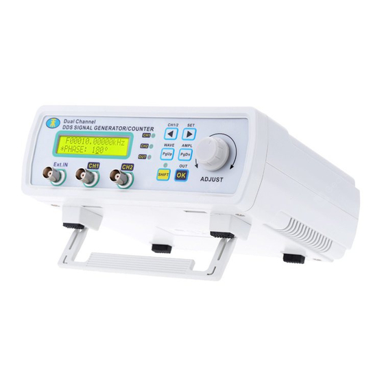
Instrument Description 1、Panel MHS-5200A Appearance Figure 2-1 shows the description of the parts as shown in Table 2-1.Figure 2-1 MHS5200A panel Table 2-1 MHS5200A Panel Grade Explanation Grade Explanation LCD1602 CH2 output interface Status Indicator DV5V power input Operation buttons communicationinterface... -
Page 8: Key Functions
Knob TTL input / output interfaceinterface Ext.In input interface CH1 output interface Switch 2、 Ribbon Description LCD instrument display is divided into two functional areas, as shown in Figure 2-2, description of the parts shown in Table 2-2. Figure 2-2 MHS5200A schematic display Table 2-2 MHS5200A Ribbon Description Grade Ribbon Description... - Page 9 Click this button to turn on or off output combination Instructions Power 1、Access 5V supply. You can use the box to configure oriented instrument powered DC5V power adapter. 2、Enter the main interface. Instructions This section will detail how to operate the instrument. It should be noted that, similar to the instrument channel CH1 CH2 channel with which the operating instructions section 1-6 also apply to CH2 channel.
- Page 10 adjusting Move the cursor to adjust the frequency step size,Then to adjust the frequency of the output waveform by rotating the "ADJUST" knob. 图 2-4 3、Setting the amplitude of CH1 In the main interface,Press Button after,The magnitude of the interface will appear in a cursor set, Click Button, It is possible to move the cursor position, rotate "ADJUST"...
- Page 11 或 ,Adjusted to offset adjustment options In the main interface,Press ,The "*" are switched to the second shown in Figure 2-7,Then click row,Click To move the cursor,Then"ADJUST" knob to adjust the offset parameter. Drawing 2-7 5、Duty cycle setting CH1 ,Adjusted to duty cycle adjustment options In the main interface,Press ,The "*"...
- Page 12 Drawing 2-9 6、Setting the display unit of frequency ,Adjusted to the frequency display unit In the main interface,Press ,The "*" are adjustment options shown in Figure 2-9, Then click switched to the second row, Then click Switching frequency units Hz、 kHz、 MHz。 图...
-
Page 13: Measurement Function
Drawing 2-11 8、External signal input port selection Select the input signal Ext.IN for input AC signal, Select TTL.IN for selecting the ,Adjust to the input input digital signal wave. In the main interface,Press ,The "*" are switched to the second port selection page, Then click row,Then click Key switch input port selection Ext.IN or TTL.IN. -
Page 14: Sweep Function
Drawing2-13 (2)After determining the measurement object, Click , Enter gate time selection page as shown below: (3)Click Bond,Select a different gate time 10S, 1S, 0.1S, 0.01S, different gate time on the frequency measurement accuracy and measurement speed. Drawing 2-14 (3) Gate time is determined, Click ,... - Page 15 Drawing2-16 ( 3 ) Enter sweep time setting page , Then click Then click The "*" are switched to the second row,Rotation "ADJUST" knob to adjust the sweep time, frequency arbitrarily set the time range between 1-600S, shown in the lower set sweep time 10S: (4)...
-
Page 16: Calibration Function
图 2-16 In the main interface, press Enter the parameter to call up the page, then click Press the key combination of "*" consumption is adjusted to the second row in Figure 2-12, then rotate "ADJUST" knob to adjust the save location, this machine a total of 10 sets of parameters stored addresses M0-M9. - Page 17 Step 2: Select the appropriate serial line after the point...
- Page 18 Step 3: Online Success 1:Output standard waveforms (1)The PC is connected, switch to expand the page, select the standard waveforms, such as pulse Sinclair...
-
Page 19: Care And Maintenance
Care and maintenance 1. Make sure the input power adapter correctly, the machine uses DC5V power adapter; 2, the instrument display on the LCD module is fragile, perishable items, please do not slam and near chemicals to prevent corrosion. When you feel the liquid surface dust and dirt, wipe with a soft cloth carefully. - Page 20 7. Do not move the instrument to avoid severe irreparable damage to the internal circuit when the instrument is working properly. Exclude the above problem re-power the instrument still does not work, please contact your supplier!
Need help?
Do you have a question about the MHS-5200A Series and is the answer not in the manual?
Questions and answers