
Summary of Contents for Laser electronics ldc1000
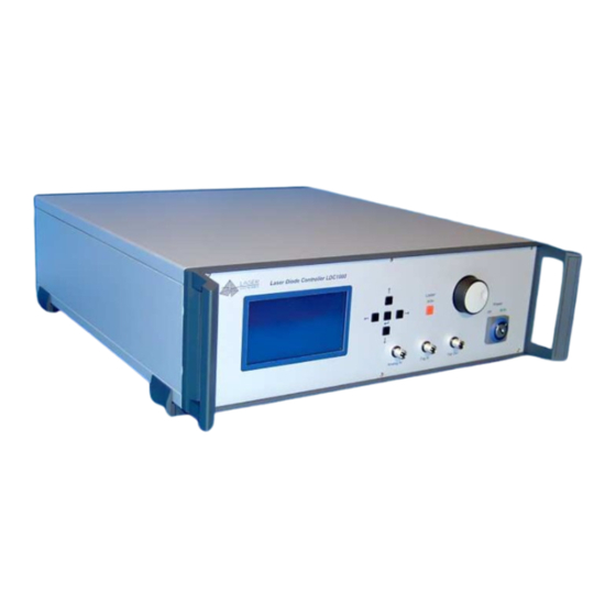
- Page 1 Laser Diode Controller LDC1000 Operating Instructions MANUAL-LDC1000 Valid from S/N:1122 Nov 2012 Rev.9.1...
-
Page 3: Table Of Contents
Contents General ....................... 4 Warranty and Assistance ..................4 Maintenance ......................4 General Safety Considerations ................4 Laser Safety ......................4 1.4.1 Laser Radiation......................4 1.4.2 Laser Class ......................4 System contents ....................6 Introduction ....................... 7 Installation ......................8 Operation ...................... -
Page 4: General
This instrument manufactured by LASER ELECTRONICS is warranted against defects in material and workmanship for a period of 12 months from date of shipment to the customer. During the warranty period, LASER ELECTRONICS will, at its option, either repair or replace products which prove to be defective. - Page 5 General warning label for laser radiation: Label for laser radiation: LASER RADIATION AVOID EYE OR SKIN EXPOSURE TO DIRECT OR SCATTERED RADIATION CLASS 4 LASER PRODUCT EN 60825-1:94 Label for relevant parameters (example) of the laser diode for normal operation and its statements: Average radiant power at max.
-
Page 6: System Contents
1.5 System contents Control Unit (Laser Diode Controller) Cable for serial interface (RS232, D-Sub 9) for interconnecting instrument with PC Connector (D-Sub 15) for interlock loop, pilot laser and power monitor AC Power Cable Manual Optional: Heat sink, air-cooled, including cables for connecting the laser diode. Laser diode mounted on heat sink. -
Page 7: Introduction
(Peltier elements). With an optional air-cooled heatsink (please contact LASER ELECTRONICS) the laser diode can easily be kept at constant temperature. The heatsink consists of a heat spreader on which the laser diode is mounted, several peltier elements for heat transportation and a large heatsink profile with fans for sufficient air flow. -
Page 8: Installation
3 Installation Please read the whole operating instructions before using this instrument together with a laser diode. Installation of the instrument Before installation check the local mains voltage. The instrument is equipped with auto-ranging power supplies for a continuous input voltage from 85 to 264 V AC @ 50 - 60 Hz. If the primary fuses are blown these can easily be replaced by the user. -
Page 9: Operation
4 Operation After installation of the laser diode, the thermoelectric cooler and the temperature sensor (respectively the heat sink) and providing the appropriate connections including installation of the Dummy interlock connector to the instrument the Laser Diode Controller is ready to be switched on. Please read the whole operating instructions before using this instrument together with a laser diode. -
Page 10: Elements Of The Instrument At The Rear Panel
4.2 Elements of the instrument at the rear panel 1. Mains fuse 2. Connector for AC line 3. Connector for Serial Interface (RS232) 4. Connector for Interlock, Pilot Laser (optional) and Power Monitor (optional) 5. Connector for Temperature Sensors and Cooler 2 (optional) 6. -
Page 11: Laser Diode Controller
The instrument is switched on with the Power switch (7). The green light emitting diode (LED) (6) indicates that all relevant components inside the instrument are supplied with power. On the back- lighted display the message „LASER ELECTRONICS“ appears for a short time and the display changes to the following window:... -
Page 12: Laser Menu
4.3.2 LASER Menu Within the laser menu you can set the optical power, the laser current, the laser mode and the laser current limit. Laser Current Limit Set the laser current limit to the indicated maximum current value of the laser diode which can be found in the individual data sheet. -
Page 13: Timing Menu
4.3.3 TIMING Menu Within the Timing menu it can be set the pulse width, the pulse period and the time limit. Confirm the value with the Enter key. The desired value is stored permanently in a non-volatile memory, even when the instrument is switched off. Notes: The two parameters “pulse width”... -
Page 14: Thermoelectric Cooler Controller
4.4 Thermoelectric cooler controller The Laser Diode Controller contains one or two optional built-in controllers for thermoelectric coolers. Cooler 1 is usually used for cooling the laser diode and delivered up to ±13A@±48V. The cooler 2 is optional and is used for customized applications (e.g.: laser crystal cooling). It delivered up to ±3A@±5V. -
Page 15: Cooler Menu
PID-Temperature control-loop parameters The temperature controller is realized as a PID control loop for optimum performance (P means proportional, I means integral and D means differential portion). The control loop parameters can be set to values between 0 and 100. The default settings which provide usually good controlling are as follows: Cooler 1 Cooler 2... - Page 16 Sensor 1/2 The Laser Diode Controller can work with three several temperature sensor types: NTC, PT100, PT1000. Attention Before changing the sensor type, make sure that: - the appropriate cooler controller is disabled, see menu COOLER, - the correct sensor type is connected on the correct connector, see section Connectors pin-out. Change the setting between NTC, PT100 and PT1000 with the Rotary knob.
-
Page 17: Instrument Settings
4.5 Instrument settings 4.5.1 PILOT LASER Menu The Laser Diode Controller can drive a pilot laser up to 300mA. Before you enable, make sure that your Laser Diode was purchased with the appropriate pilot laser, see Delivery Note. This source deliver constant voltage (+5,0V) for a build in pilot laser (with integrated small driver). -
Page 18: Error Messages
4.6 Error Messages Interlock error If interlock loop is opened, the laser is turned off immediately and the following message appears on the display: ERROR INTERLOCK OPEN The error massage must be confirmed by pressing the Enter key. After the interlock loop is closed again, the laser diode can be turned on again by pressing the Laser key. - Page 19 If the controller detects an internal error on the controller unit, the laser diode and the thermoelectric coolers are turned off immediately. The following message appears on the display: ERROR CONTROLLER UNIT ERROR If this error occurs, please contact LASER ELECTRONICS for repair.
-
Page 20: Connectors Pin-Out
Fix the leads to the appropriate connectors supplied with your laser diode. If the instrument comes with a heat sink provided by LASER ELECTRONICS, only the wiring between the laser diode and the two coloured leads (red and black) at the heat sink according the subsection „laser diode“... -
Page 21: Laser Diode
5.1 Laser diode The instrument must be turned off before making the connection. Up to 70A laser driver current the instrument comes with a laser diode connector. For higher currents the cables are fixed connected at the device. The connector for the laser diode (5) is located at the rear panel of the instrument and it is a male type. -
Page 22: Thermoelectric Cooler 1
5.2 Thermoelectric cooler 1 The instrument must be turned off before making the connection. The connector for the cooler 1, the temperature sensor 1 (type: NTC) and the fan (as of the heat sink) (6) is located at the rear panel of the instrument and it is a female type. The pin-out is shown when facing the connector mounted to the rear panel directly. -
Page 23: Thermoelectric Cooler 2
5.3 Thermoelectric cooler 2 The instrument must be turned off before making the connection. The connector for the cooler 2 and for the temperature sensors (4) is located at the rear panel of the instrument and it is a 25 pol. SUB-D female type. 25pol. -
Page 24: Interlock, Pilot Laser, Power Monitor
5.4 Interlock, Pilot Laser, Power Monitor The connector for the interlock, pilot laser and power monitor (3) is located at the rear panel of the instrument. The connector at the rear panel is a D-Sub 15, female. The pin-out is shown when facing the connector mounted to the rear panel directly. Pin number Designation Remark... -
Page 25: Serial Interface
Pin2 = Reference (Signal Ground) Some laser diode modules include a pilot laser. The LDC1000 is provided with a pilot laser control feature. It can deliver 5V at max. 300mA. Please note, that this power supply is a constant voltage power supply and can not drive laser diodes directly. -
Page 26: Interfaces Command Description
6 Interfaces command description The instrument can be remotely controlled by a PC. All parameters can be set and read-out with a choice of commands including turning on and turning off of the laser diode. 6.1 Serial interface Please make the appropriate connection with the provided cable from a free serial port of the PC to the serial interface connector of the Laser Diode Controller. - Page 27 The Laser Diode Controller accepts only parameter values which are within the predefined range or within the limits which have been set. Note: The word <Enter> represents the ENTER key on the PC keyboard. The following parameters can be read or read and set: Command Abbreviation Parameter Read...
- Page 28 ∗ Actual case temperature °C ∗ Error status Remark: Some terminal programs send out the corresponding code right after the key was hit. Therefore a wrong input must be finished with hitting the ENTER key on the PC and the input must be repeated. Note: The value for the temperatures, the upper and lower temperature limits must be within 0°C to 50°C.
- Page 29 • Sensor type (set CS1 v) The value for setting sensor type: Value v Sensor type PT100 PT1000 E.g. set CS1 0 sets cooler sensor 1 of NTC. • Error status (get ERR) Following associations of values which will be returned are valid: Value v Error status No error...
-
Page 30: Specifications
7 Specifications Laser Diode Controller Power Laser Diode Driver 300 W 600 W 1.500 W (corresponding order) Max. Laser Diode Current 50A 100A 120A 150A 55A 65 A 100A 125A Max. Laser Diode Voltage 5 V 3,6V 3,6 V 28V 24 V 15 V 12 V Ripple / Noise (rms) [mA] 100... - Page 31 TEC Controller Temperature Range 0 ... 50 °C Temperature Stability < 0,1 K Temperature Adj. Accuracy 0,1 K Control Loop Output Cooler 1 TEC Output Power (corresponding order) 300 W 600 W 0.. ±7 A 0.. ±12 A 0.. ±14 A 0..
Need help?
Do you have a question about the ldc1000 and is the answer not in the manual?
Questions and answers