
Subscribe to Our Youtube Channel
Summary of Contents for V-TEK OEM TM-50 SMD
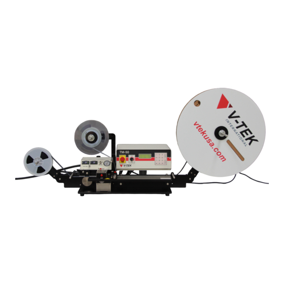
- Page 1 OEM TM-50 SMD Taping Module User’s Guide User’s Guide # 61685741 V-TEK, Inc. 751 Summit Avenue Mankato, MN 56001 (P) 507-387-2039 www.vtekusa.com...
- Page 3 EC Declaration of Conformity Manufacturers Name: V-TEK Incorporated Manufacturers’ Address: 751 Summit Avenue Mankato, MN 56001 USA Declare that the machinery described below complies with applicable health and safety requirements of Part 1 of Annex 1 of the Machinery Directive 2006/42/EC and EMC Directive 2004/108/EC. Confidential technical documentation has been compiled in accordance with Part A of Annex VII of Machinery Directive 2006/42/EC and is available to European national authorities on written request only.
-
Page 5: Theory Of Operation
Preface This User’s Guide describes how to setup and operate the TM-50 Taping Machine. This manual should be read and thoroughly understood before operating the machine. The TM-50 Taping Machine is built with the following standard features. Features: • Adjustable track assembly for tape widths 8mm to 56mm •... - Page 6 • 115/230 VAC, 50-60 Hz • Compressed air, 80 PSI Contact Information V-TEK, Inc. 751 Summit Ave Mankato, MN 56001 TEL: (507) 389-2039 website: http://www.vtekusa.com For customer service, please refer to the Customer Service Contact Sheet at the back of this manual.
-
Page 7: Intended Use
Intended Use The intended use of the TM-50 Taping Machine is to produce taped reels of individually sealed and consistently orientated components. It is designed to accommodate a full range of electronic devices. Use of this equipment in any other way is not recommended. Suitable carrier and sealing tapes include any conductive or non-conductive tapes with feed- holes that are pitched at 4 mm. -
Page 8: Safety Precautions
Safety Precautions General Precautions Only qualified personnel with the proper technical training, experience working on this type of equipment, and awareness of the possible hazards should perform maintenance on the TM-50. The TM-50 should be installed on a level and stable surface before any operation or mainte- nance is performed. - Page 9 Indicates areas where moving parts can cause personal injury if safety precau- tions are not observed. Open Book Refer to Chapter 4 of this manual before performing maintenance on the TM-50. Contact Information V-TEK, Inc. 751 Summit Ave Mankato, MN 56001 TEL: (507) 389-2039 website: http://www.vtekusa.com For customer service, please refer to the Customer Service Contact Sheet at the back of this manual.
- Page 10 Safety Warning Labels 61685113.fm...
-
Page 11: Table Of Contents
OEM TM-50 Table of Contents EC Declaration of Conformity Preface Theory of Operation ...........i Machine Details . - Page 12 OEM TM-50 Table of Contents (continued) Exploded Views Appendix A - Sensors Appendix B - Temperature Controller Settings Spare Parts List Service and Parts Contacts Document List Warranty Document...
- Page 13 Chapter 1: Getting Started Contents Preparing the Work Area ........2 Unpacking the OEM TM-50 .
- Page 14 OEM TM-50 User’s Guide Preparing the Work Area The OEM TM-50 is a table-top machine which needs to be mounted on a flat, stable surface in a well lit area that is a minimum of 6’ high x 10’ wide x 5‘deep (2m x 3m x 1.5m). When positioning the OEM TM-50, choose an area that is not located below overhead gantries, walkways or power lines to ensure objects or liquids cannot be dropped on the machine from overhead.
- Page 15 Chapter 1: Assembly and Illustrations When running the OEM TM-50, the operator should stand in front of the machine controller to assure easy access to all controls and the Power/Emergency Stop button. This position also allows the operator to view all parts of the OEM TM-50 while it is in operation. Allow at least 24”...
- Page 16 OEM TM-50 User’s Guide Unpacking the OEM TM-50 The following items should be included in the shipping crate: Figure 1.1 A. Cover Tape Reel Support Controller E. Controller Baseplate B. Take-up Motor Assembly F. Air Regulator C. Feed Reel Support G.
- Page 17 Chapter 1: Assembly and Illustrations Assembling the OEM TM-50 Before the OEM TM-50 is shipped from V-TEK, the machine is disassembled to prevent damage in transit. Follow these instructions to reassemble the machine: 1. Remove items one at a time from the crates and place on a flat, stable surface for assembly.
- Page 18 OEM TM-50 User’s Guide 3. Attach the Take-up Spindle to the Take-up Motor Assembly by sliding it onto the pin and tightening the set screw with a 3/32” hex wrench. Figure 1.5 4. Remove the black knob from the left side of the Take-up Motor Receptacle track support bracket.
-
Page 19: Assembling The Oem Tm-50
Chapter 1: Assembly and Illustrations 7. If the OEM TM-50 includes a Pedestal to mount the OEM TM-50 Controller, attach the Controller Baseplate to the Pedestal using the provided screws. Place the Controller on the Controller Baseplate. Engage the (4) corner holes in the Controller Baseplate with the (4) rubber feet on the bottom of the Controller so that it is seated securely. - Page 20 OEM TM-50 User’s Guide 11. Install the Air Regulator on the back of the Sealer Controller with the provided screws. Attach the blue air hose to the air fitting on the right side of the Sealer Control Box. 12. Connect a 1/4” airline to the Air Regulator and set the regulator to 80 psi, if necessary.
- Page 21 Chapter 1: Assembly and Illustrations Machine Overview Before the OEM TM-50 is placed in operation, use the photos in the following section to perform a visual inspection and ensure that it is correctly assembled. Front Figure 1.14 A. Controller H. Sealer B.
- Page 22 OEM TM-50 User’s Guide Back Figure 1.15 A. Tape Guides F. Air Regulator B. Sensor Amplifiers G. Controller Back C. Empty Pocket Detector (EPD) H. Take-up Arm D. Cover Low Sensor I. Carrier Tape Arm E. Cover Tape Arm Serial Plate Machine Overview 61685225.fm...
-
Page 23: Machine Overview
Chapter 1: Assembly and Illustrations Left Side Figure 1.16 A. Take-up Motor E. Rear Tape Guide B. Take-up Reel Spindle F. Drive Sprocket C. Peripheral Connector G. Idler Wheel D. Take-up Motor Connector Heat Sealer Controls Figure 1.17 A. Inside Seal Temperature Control D. - Page 24 OEM TM-50 User’s Guide The Universal Sealer Figure 1.18 A. Inner Seal Position Lock F. Cover Tape Guide Width Outer Adjuster B. Inner Seal Position Adjuster G. Cover Tape Guide Width Screw C. PSA Seal Pressure Adjustments H. Outer Seal Position Lock D.
- Page 25 Chapter 1: Assembly and Illustrations Loading Track Figure 1.19 A. Inner Loading Track B. Outer Loading Track C. Carrier Tape Guides Sensors Figure 1.20 61685225.fm Machine Overview...
- Page 26 OEM TM-50 User’s Guide A. Low Cover Sensor: The Low Cover Sensor detects when the cover tape reel is running low and alerts the user. B. Carrier Low Sensor (optional) : The Carrier Low Sensor detects when the carrier tape reel is running low and alerts the user.
- Page 27 Chapter 1: Assembly and Illustrations Controller Back Panel Figure 1.22 A.Vision Connects the TM-50 to optional Vision Systems. B. Sensor Thru Allows external machines to monitor the TM-50’s sensors. C. I/O Connects the TM-50 to optional auto-feed mechanisms. D. Peripheral Connects the TM-50 controller to the base machine.
- Page 28 OEM TM-50 User’s Guide Machine Overview 61685225.fm...
-
Page 29: Chapter 2: Controller
Chapter 2: Controller Contents The OEM TM-50 Controller ........16 Extended Software Option . -
Page 30: Setup Menu
When the OEM TM-50 is powered up, the con- with the exception of the sealer temperature troller will display an initial welcome screen controls and the take-up tension control. shown in Figure 2.3. V-TEK TM50 SETUP Figure 2.3 From this screen, the operator can choose to... - Page 31 Chapter 2: Controller When a menu option is selected, a new stop message on the Run screen (Figure 2.7). screen will appear. These screens are ***STOP REACHED*** described below. press ESC to exit Count Speed Stop Count The count screen (Figure 2.5) is used to clear 2500 2500 the current parts count value to 0 and to set...
- Page 32 OEM TM-50 User’s Guide Advance Dwell This screen (Figure 2.10) prompts the user to This screen (Figure 2.12) allows the operator enter the number of pockets to advance each to adjust the length of time the heat shoes will time the foot switch is pressed or an advance remain in contact with the tape during a seal command is sent to the controller using the I/O stroke.
- Page 33 Chapter 2: Controller Integration To move the tape, press the arrow key on the keypad pointing in the desired direction. The Pressing 4>INTEGRATION on the MODE tape will jog the selected distance each time screen will bring up the screen shown in Fig- an arrow key is pressed.
- Page 34 OEM TM-50 User’s Guide Note: When determining the leader/trailer When the right arrow key is pressed in the length, please note that the final length will Integration screen, a second screen of options be 450 mm plus the leader/trailer length will appear: value that is entered in the controller set- tings.
- Page 35 Chapter 2: Controller When RUN is selected, this screen (Figure 2.20) will be displayed and the TM-50 will ready to operate. Pitch V-TEK Dwell Advance PSA Speed Stop Count 2500 Figure 2.20 The parameters which have been entered are displayed on the screen along with the running parts count.
-
Page 36: Extended Software Option
OEM TM-50 User’s Guide Extended Software Option The extended OEM TM-50 software option shown in Figure 2.24. improves on the system control with a number of additional features. 1>COUNT 2>PITCH 3>ADVANCE 4>SPEED V-TEK TM50 5>DWELL 6>JOG 7>MODE NEXT -> SETUP <- ->... - Page 37 Chapter 2: Controller These choices allow the user to toggle each of key is pressed, the display will cycle through the listed the sensors installed on the machine three settings: OFF, 1, and 2. to ON and OFF. An asterisk indicates the option is turned ON.
- Page 38 OEM TM-50 User’s Guide choice screen, as shown in Figure 2.24. Choose the NEXT key. The second screen shown will appear. 1>COUNT 2>PITCH 3>ADVANCE 4>SPEED 5>DWELL 6>JOG 7>MODE NEXT -> 8>STORE AS JOB 9>RUN THESE SETTINGS Figure 2.28 It is now an option to either continue to Run Mode with the chosen settings or to save the settings to a specific job number.
-
Page 39: Using The Vision Port
Chapter 2: Controller Using the Vision Port It is simple to use a vision system with the TM-50. Connect as indicated by the diagram shown in Figure 2.30. All input and output from this port is open collector/drain. Signals are referenced to the 0V ground pin (DB9-5). - Page 40 OEM TM-50 User’s Guide V-TEK recommends the following timing values for Vision Mode 1. Vision Mode 1 Timing Trigger (pin 4) +5V DC 50ms Busy (pin 1) +5V DC 50ms Pass/Fail (pin 3) Fail Signal DC COM Figure 2.31 Using the Vision Port...
- Page 41 Chapter 2: Controller Vision Mode 2 DB9-1 is not used as a BUSY signal in this setup to allow Vision Systems without BUSY signals to be integrated. In this instance, identical signals on both DB9-1 and DB9-3 are needed. 1. The OEM TM-50 will pull the TRIGGER signal (DB9-4) low for 10ms. 2.
- Page 42 OEM TM-50 User’s Guide V-TEK recommends the following timing values for Vision Mode 2 for a PASS condition. Vision Mode 2 Timing (TM-50 Search Time Frame) Trigger (pin 4) +5V DC 10ms 100ms Busy (pin 1) +5V DC 100ms Pass/Fail (pin 3)
- Page 43 Chapter 2: Controller Vision Hookup Example Figure 2.33 6174007.fm Using the Vision Port...
- Page 44 OEM TM-50 User’s Guide Using the Comm Port If the OEM TM-50 is connected to the serial port of a computer, the computer can call up any of the preprogrammed jobs. Send the number 01--64 to the OEM TM-50 and it will immediately load that job and go into run mode.
-
Page 45: Chapter 3: Setup And Operation
Chapter 3: Setup and Operation Contents Preparing to Run a Job ........32 Quick Setup Guide . -
Page 46: Preparing To Run A Job
14. Set the Counter. 15. Run the job. Caution! V-TEK® Incorporated takes no responsibility for the safety of the OEM TM-50 if it is used for any purpose other than the intended purpose as specified in this User’s Guide. Preparing to Run a Job... -
Page 47: Setup
Chapter 3: Setup and Operation Setup Connect Power and Air Supply 1. Ensure the power and compressed air supplies are connected to the machine, as described in Chapter 1. Note: The air pressure should be set somewhere Air Line Air Supply between 80 psi, the minimum recommended air pres- sure, and 110 psi, the maximum recommended air pressure. - Page 48 OEM TM-50 User’s Guide Load Tapes Detent Shafts Figure 3.2 Adjust the Width of the Loading Track The width of the loading track adjusts by moving the front track in and out on two shafts. The shafts have detents that engage the front track at standard widths to accommodate 8-56mm car- rier tapes.
- Page 49 Chapter 3: Setup and Operation 2. Mount the bulk Carrier Tape Reel on the spindle so the tape unwinds from the top and the sprocket holes of the car- rier tape are on the inside for tape widths less than 32mm. Tapes wider than 32mm have holes on both sides.
- Page 50 OEM TM-50 User’s Guide 3. Guide the carrier tape over the (2) Tape Guides which are located at the right end of the Loading Track. It should feed through the loading track easily. Lowering the Feed Reel Support Arm can reduce drag if the angle at which the carrier enters the loading track is too steep.
- Page 51 Chapter 3: Setup and Operation Mount the Cover Tape 1. Place a reel of cover tape of the correct width to match the carrier tape on the Cover Tape Spindle. The tape should unwind to the right from the bottom of the reel.
- Page 52 OEM TM-50 User’s Guide 5. Check the tension of the cover tape by observing if there Tension Adjustment Knob is excess slack as the cover tape is pulled through the sealer. If so, the tension is too little. If there is no slack, check that the tension is not too tight by pulling the tape by hand.
-
Page 53: Heat Seal Setup
Chapter 3: Setup and Operation Heat Seal Setup If a PSA Seal is desired, proceed to the next section. 1. If the TM-50 was previously used for PSA Seal, loosen the Seal Roller Pressure Screws until the Sealer Rollers are no longer in contact with the tape. PSA Seal Pressure Adjustment... - Page 54 OEM TM-50 User’s Guide 4. Set the temperature controls to the appropriate temperature. Refer to the table below or to Appendix B: Temperature Controller Default Settings. TEMPERATURE IN DWELL TIME IN CARRIER TAPE TYPE COVER TAPE TYPE PRESSURE IN PSI CELSIUS MILLISECONDS CONDUCTIVE BLACK...
- Page 55 Chapter 3: Setup and Operation 9. Check the sealed tape for the desired seal position. Inner Seal Adjust Position Locks Figure 3.16 Outer Seal Adjust The width of the Sealer Shoe positions is adjusted by the white, toothed seal position adjusters on either side of the sealer.
-
Page 56: Psa Seal Setup
OEM TM-50 User’s Guide PSA Seal Setup 1. Turn the heat seal switch OFF. Figure 3.17 2. Refer to the Controller chapter to set the controller to PSA operation and place it in the Run Mode. 3. Advance the tape using the Foot Switch. 4. -
Page 57: Testing Seal Strength
Perform as many Peel Force Tests as needed while adjusting the sealer controls to obtain the required seal strength. Instructions for Peel Force Test vary from one manufacturer to another. Follow the manufac- turer’s instructions for the Peel Force Tester selected to perform the test. A V-TEK PT-55 Peel Force Tester is pictured below. 61685321.fm... -
Page 58: Operation
OEM TM-50 is ready for operation. Caution! V-TEK® Incorporated takes no responsibility for the safety of the OEM TM-50 if it is used for any purpose other than the intended purpose as specified in this User’s Guide. - Page 59 Chapter 3: Setup and Operation Check Carrier Tape Alignment To ensure an accurate count, select a spot on the loading track as a reference point for the first and last parts counted. Examples of reference points include the edge of the stainless steel Carrier Tape Guide, one of the fas- tener heads, or the Track Width Lock Knob.
-
Page 60: Using The Empty Pocket Detector
OEM TM-50 User’s Guide Using the Empty Pocket Detector Set up EPD 1. In the Controller Setup Menu, select Mode, and then press 3 to enable or disable the EPD Sensor. 2. Position the sensor over an empty pocket and press the SET button on the Keyence Sensor Amplifier. - Page 61 Chapter 3: Setup and Operation Completion When the counter reaches the STOP value set in the Controller, the machine will stop. The last part that was counted will be under the sensor. Remove any additional parts in the loading track that may be remaining.
-
Page 62: Using E-Stop In Malfunction/Fail Situations
OEM TM-50 User’s Guide Using E-Stop in Malfunction/Fail Situations There is one Emergency Stop button located on the front of the OEM TM-50 controller. When the emergency stop is activated, all operations cease. If a jam in tape or some other malfunction occurs, follow the steps below to resolve the failure. -
Page 63: Chapter 4: Maintenance Instructions
Chapter 4: Maintenance Contents Safe Maintenance Steps ........50 Safe Maintenance Steps . -
Page 64: Safe Maintenance Steps
OEM TM-50 User’s Guide Safe Maintenance Steps Follow the steps below when performing routine maintenance or cleaning on the OEM TM-50. Turn the OEM TM-50 OFF. Disconnect the air supply and place the unplugged air hose so it clearly visible. Disconnect the power supply and place the unplugged power cord so it clearly visible. - Page 65 Chapter 4: Maintenance Maintenance Schedule The OEM TM-50’s simple, low-maintenance design keeps required maintenance to a minimum. The following schedule indicates common maintenance tasks and how frequently they should be performed. Maintenance Task Schedule Materials needed Heat Sealer every 40 hours of operation •...
-
Page 66: Maintenance Instructions
OEM TM-50 User’s Guide Maintenance Instructions Heat Sealer Heat Sealer maintenance consists mainly of cleaning built-up debris and adhesive residues from the Heat Shoes. It should be cleaned after every 40 hours of operation. To clean the Heat Shoes, follow the steps below. 1. - Page 67 Chapter 4: Maintenance 5. Clean the residues from the Heat Shoes by using a plastic or brass brush soaked in alcohol. Do not use a steel bristled brush. If there are some tough spots that will not come clean, the sealer can be heated by plugging it into the Taping Machine, and then scraping it with the handle of a wood brush or some other wooden implement.
- Page 68 OEM TM-50 pneumatic system should not require adjustment or replacement. Should an issue with the pneumatic system arise, call V-TEK Service for assistance. PSA Sealer The adhesive residues should be cleaned from the Sealer Assembly every 40 hours of operation.
- Page 69 Chapter 4: Maintenance Fuses The machine is fused with (2) 2A 5mmx20mm SLO BLO fuses installed in a fuse holder in the AC Filter, just beneath the AC Power Receptacle. Replace as needed. Lubrication No lubrication is required or desired on the OEM TM-50 as all parts are no maintenance in this regard and the use of lubricants could interfere with components.
-
Page 70: Electrical Connections
OEM TM-50 User’s Guide Electrical Connections I-O Port (J1) All output pins of the I-O port (J1) are open collector devices. The I-O port pins are referenced to the pin 4 ground level. The receptacle used is an AMP 206705-1 with 66103-4 male pins. The mate would be AMP 206708-1 plug, with 66105-4 socket pins. - Page 71 Chapter 4: Maintenance Interface Information Input Pin 1 - external advance signal - a logic low starts advance. Pin 1 is internally pulled up to 5VDC. Use an open collector device to control this pin. Do not exceed 5VDC. Output Pin 2 - fault signal - a logic low indicates an empty pocket or other sensor fault Pin 3 - ready/busy signal - a logic low indicates the...
- Page 72 OEM TM-50 User’s Guide If the AC system used to power the TM-50 is a single phase system, where the neutral leg con- nects to the chassis ground at the fuse box, DC ground could also be connected to AC neutral without problem.
- Page 73 Chapter 4: Maintenance Figure 4.5 6174322.fm Electrical Connections...
- Page 74 OEM TM-50 User’s Guide Figure 4.6 Electrical Connections 6174322.fm...
- Page 75 I S I I T I & : ) s...
- Page 76 I F I " 8 & : ) s...
- Page 77 I F I & : ) s...
- Page 78 " 2 " 0 & : ) s...
- Page 79 " 8 & : ) s...
- Page 80 I F I & : ) s...
- Page 81 & : ) s...
- Page 82 , L I & : ) s...
- Page 83 . T . . T . . T . . T . . T . . T . " 0 . T . & : ) s...
- Page 84 " 2 " 2 & : ) s...
- Page 85 & : ) s...
- Page 86 " 6 " 4 & : ) s...
- Page 87 & : ) s...
- Page 88 & : ) s...
- Page 89 " 3 " 1 " 1 " 2 " 2 " 2 - " - " - " - " - " - " - " & : ) s...
- Page 90 I S I & : ) s...
- Page 91 & : ) s...
- Page 92 & : ) s...
- Page 93 " " T & : ) s...
- Page 94 & : ) s...
- Page 95 Appendix A: Sensors Appendix A: Sensors 61004015.fm...
- Page 96 Appendix A: Sensors Keyence FS-V21/FS-V22 Sensor Amplifiers The Keyence FS-V21 and FS-V22 sensor amplifiers (shown in Figure A.1) are used on the TM-50 for both the low cover tape sensor and the empty pocket detector. The V21 is the low cover tape amplifier unit and V22 is the EPD amplifier unit.
- Page 97 Appendix B: Temperature Controller B- 1 Appendix B: Temperature Controllers Contents Omron E5GC Temperature Controller ......B-2 61574415.fm...
- Page 98 Refer to the Omron E5GC User’s Guide when necessary for more detailed technical information regarding the operation of the termperature controllers. The directions below describe the factory settings set at the time the controllers are installed at V-TEK, Inc. Operation Level Settings (Figure 1.1) 1.
- Page 99 2. The Input Type parameter will display as In-T. It should be set to 7. This setting corresponds to the J type thermocouple used in V-TEK sealers. 3. Select the Temperature Unit parameter, displayed as d-u, by pressing the Mode Key.
- Page 100 B- 4 TM-50 User’s Guide Adjustment Level Settings (Figure 1.3) 1. While still in the Initial Settings Level, press the Level Key once for less than one second. The controller will enter the Adjustment Level. 2. The initial parameter displayed is the Auto-tuning parameter, displayed as At. It should be set to off.
- Page 101 751 Summit Avenue Mankato, MN USA 56001 Website: www.vtekusa.com Email: service@vtekusa.com Phone: (507) 387-2039 For inquiries regarding spare parts, tape and reel supplies, or the ser- vice department, please call or write: Phone: (507) 387-2039 Email: service@vtekusa.com Please provide the machine model and serial numbers with all inquiries. NOTES ____________________________________________________________ ____________________________________________________________...
- Page 102 Service and Parts Contacts 61053915.fm Page 2...
- Page 103 Spare Parts List OEM TM-50 Part Number Description Quantity Controller 102025 LCD display 102357 Main micro chip 103499 Transformer (new style) 103504 Transformer (old style) 109054 Keypad 112557 Fuse 2 amp (5x20 mm) 150032 AC auto select board (new style) 150038 AC auto select board (old style) 150048...
- Page 105 Spare Parts List OEM TM-50 Sensors Part Number Description Quantity EPD Sensor 104949 FS-V21R Amplifier (new style) 104951 FS-V11 Amplifier (old style) 104952 FU-35FA Fiber Optic EPD Black Position Knob 217022 Black Cap 261268 Thumbscrew Knob Low Cover Tape Sensor 104949 FS-V21R (new style) 104951...
- Page 106 TM-50 OEM Sensors Spare Parts List D219368.2.fm Page 1 of 1...
- Page 107 OEM TM-50 Document List Section Description File Name Front Cover Page 1 of 1 61685028.fm EC Declaration of Conformity Page 1 of 1 TM-50 DOC.pdf Preface Pages i-vi 61685113.fm Table of Contents Page 1 of 1 61647517.fm Chapter 1: Getting Started Pages 1-14 61685225.fm Chapter 2: Controller...
- Page 109 12. The warranty applies only to normal use of the equipment and shall be void if V-TEK determines that defects in or failures of the equipment were caused by the Customer’s negligence including the lack of proper preventative maintenance, misuse or accident or by unauthorized repair, alteration or installation.
- Page 112 751 Summit Avenue Mankato, MN 56001 (507) 387-2039 FAX: (507) 387-2257 www.vtekusa.com Email: info@vtekusa.com...
Need help?
Do you have a question about the OEM TM-50 SMD and is the answer not in the manual?
Questions and answers