
Summary of Contents for Digitimer DS5
- Page 1 Digitimer DS5 Isolated Bipolar Constant Current Stimulator OPERATOR’S MANUAL 0120 “Digitimer” is a registered trade mark of Digitimer Limited...
- Page 2 DS5 Isolated Bipolar Constant Current Stimulator DS5 Operator's Manual 5.0 Product Registration Please take time out to register your new product. Details are included in the General Information Chapter You can even do it online at:- www.digitimer.com/register Digitimer Ltd. 2 of 52...
-
Page 3: Table Of Contents
DS5 Isolated Bipolar Constant Current Stimulator DS5 Operator's Manual 5.0 Table of Contents CHAPTER 1 GENERAL INFORMATION....................7 Product Description & Intended Usage...............7 Precautions & Warnings..................8 Operator’s Manual..................8 Risks to Patient Safety................8 Patient Exclusion Criteria................8 Explosion and Fire..................8 High Voltages...................8 Damage....................9 Moisture....................9... - Page 4 DS5 Isolated Bipolar Constant Current Stimulator DS5 Operator's Manual 5.0 Obtaining Warranty Service................18 Product change or discontinuation..............18 CHAPTER 2 HARDWARE INSTALLATION..................19 Tour of the Hardware..................19 Introduction.....................19 Front Panel Components...................19 Front Panel Symbols..................20 Rear Panel Components..................21 Rear Panel Symbols..................21 Audible Alerts & Warnings................22 Initial Hardware Check..................22...
- Page 5 Visual Inspection..................35 Electrical Tests..................35 Functional Test..................36 Evaluation, Documentation and Preparation for Normal Use......36 ANNEX 2:- Installing & Using the DS5 User Interface (DS5 UI) Software..37 Installation of the DS5 UI Software..............37 Using the DS5 UI Software................40 DS5 Device List..................40 DS5 Console...................42 Menu &...
- Page 6 DS5 Isolated Bipolar Constant Current Stimulator DS5 Operator's Manual 5.0 Digitimer Ltd. 6 of 52 Copyright © 2009...
-
Page 7: Chapter 1 General Information
The DS5 meets all the requirements of the Medical Device Directive (MDD) by implementing the EN 60601 Standard. The Digitimer DS5 stimulator is intended to be used by persons trained in its use, who are expected to be familiar with the principles and safety issues of electrical stimulation. Users should be able to operate the DS5 stimulator, the controlling software, and any associated instruments correctly before carrying out any patient or human volunteer studies. -
Page 8: Precautions & Warnings
Stimulating electrodes should not be placed thoracically or trans-thoracically as this may increase the risk of cardiac fibrillation. A warning to this effect is given on the outside of the DS5. Care should be taken when selecting appropriate stimulating electrodes. If the current density of ... -
Page 9: Damage
If any ‘strange’ behaviour of the unit is noted, discontinue use immediately and refer to a qualified EMC engineer. The DS5 stimulator should not be used adjacent to or stacked with other equipment. If such use is required, then the behaviour of the stimulator should be monitored to confirm normal operation in this configuration. -
Page 10: Regulatory Statements
DS5 Isolated Bipolar Constant Current Stimulator DS5 Operator's Manual 5.0 Regulatory Statements EU Declaration of Conformity Digitimer Ltd. 10 of 52 Copyright © 2009... -
Page 11: En 60601 (Iec 60601):1990 Classifications
(chargeable) to fully qualified, and certified, service repair centres. Modification Status The green and white serial number label affixed to the rear of each DS5 contains the unique serial number of that unit. This serial number should be quoted whenever technical support is requested from Digitimer or one of our representatives. -
Page 12: Unpacking
At the time of writing, no changes to the DS5 have caused a rise in the MOD RECORD STATUS, hence no numbers are crossed out. -
Page 13: Mains Plug Connections
If it is possible to fit a fuse into the mains plug, this should be of the correct style and be rated at 3 Amps. Mains Voltage Selector The DS5 mains voltage selector should be correctly configured for the local mains voltage supply. Four voltage options are available (240V, 200V, 120V and 100V) and these are selected by appropriately positioning both jumpers located in the “Voltage Selector”... -
Page 14: Product Registration
This web address is your point of contact for all questions regarding the DS5. The contents of this site are now growing rapidly, so please bookmark it so that you can visit it regularly to check out the new items. -
Page 15: Contact Addresses
+49 (0) 611 185 1946 E-mail: helmutwehking@wehking-med.de Australia/New Zealand: MedTel 5 Orion Road Lane Cove, NSW 2066, Australia Telephone: +61 2941 36284 Fax: +61 2942 77329 Please contact Digitimer for information regarding representation in other countries. Digitimer Ltd. 15 of 52 Copyright © 2009... -
Page 16: Purchase Information
DS5 Isolated Bipolar Constant Current Stimulator DS5 Operator's Manual 5.0 Purchase Information A record of salient information will aid the operator should it be required in the future:- Date of Purchase: Dealer: Dealers Telephone Number: Dealers Fax Number: Dealers E-mail Address:... -
Page 17: Specifications
DS5 Isolated Bipolar Constant Current Stimulator DS5 Operator's Manual 5.0 Specifications Output: Bipolar constant current proportional to the input voltage (+ve input voltage gives rise to an output current where RED socket becomes +ve with respect to BLACK socket). Output Ranges: ±10;... -
Page 18: Warranty Information
Warranty Information Limited Warranty Digitimer Limited warrants to the first purchaser, for a period of one year from the date of purchase, that this Digitimer instrument (hereafter referred to as the “Product”) will be free from defective workmanship and materials, and agrees that it will, at its option, either repair the defect or replace the defective Product or part thereof at no charge to the purchaser for parts and labour. -
Page 19: Hardware Installation
±50mA for patient stimulation. The input voltage signal is fed into the DS5 via a BNC socket on the rear of the stimulator. The other pair of BNC sockets, which are used for stimulus monitoring, output a voltage waveform proportional to the actual stimulus voltage or current supplied to the patient. -
Page 20: Front Panel Symbols
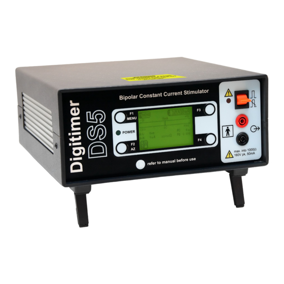
Figure 2.1 Front Panel Components of the DS5 Stimulator Front Panel Symbols The front panel of the DS5 has several symbols which the operator should become familiar with before starting to use the stimulator. Upward deflection of the toggle switch Attention, consult accompanying documents. -
Page 21: Rear Panel Components
3. Control - Type B USB socket providing a USB interface COM port to link the DS5 to a remote personal computer running Windows 2000 or Windows XP. This socket allows for future updates to... -
Page 22: Audible Alerts & Warnings
1. Ensure that the power supply switch on the rear of the DS5 is in the OFF (O) position. 2. Ensure that the mains inlet fuses installed are appropriate for your mains supply voltage and that the voltage selector jumpers are in the correct position for your local mains supply voltage. -
Page 23: Chapter 3
This allows any temperature sensitive components to equilibrate. 10. The DS5 is now ready to be configured for the particular hardware it is to be interfaced with. Configuration should be carried out using the front panel Operator Interface, which is more thoroughly discussed in Chapter 3 –... - Page 24 DS5 Isolated Bipolar Constant Current Stimulator DS5 Operator's Manual 5.0 Digitimer Ltd. 24 of 52 Copyright © 2009...
-
Page 25: Configuration And Operation
The Main Operating Screen The Main Operating Screen is the default screen when the DS5 is in use and it provides the operator with an instant display of various continuously measured parameters as well as the selected input voltage and output current ranges. - Page 26 Autozero not possible due to an excessive DC offset on the input (left). Autozero not possible due to oscillations on the input (right). Iconic display of the following adjustable DS5 settings: Input Voltage Range:- ±1V, ±2.5V, ±5V or ±10V (shown) Output Current Range:- ±10mA (shown), ±25mA or ±50mA...
-
Page 27: Configuring The Ds5
Most of the choices in the options menu provide the operator with an opportunity to modify the default settings of the DS5. The various choices are further described below and should be carefully defined before the DS5 is connected to any external devices or subjects. -
Page 28: Enabling And Disabling The Audible "Information" Alerts
Patient safety is of paramount importance when designing an electrical stimulator for clinical use. As a result the DS5 incorporates several layers of safety features, many of which will never be apparent to the operator. Amongst these are four output limits which control stimulus pulse energy, current and pulse duration. -
Page 29: Exceeding An Enabled Limit
3. The voltage source should then be connected to the Voltage Input BNC socket on the rear of the DS5, using an appropriate cable. 4. Before a voltage signal is applied to the DS5, it is necessary to press the F2/AZ key to autozero the Digitimer Ltd. -
Page 30: Monitor Output Connections
Connecting to a Dummy Load We advise all new operators of the DS5 to simulate a protocol before a human subject is used. To do this we suggest that the operator fabricates a “dummy load circuit” by placing a 1kohm (11 Watt) resistor between the stimulus output sockets of the DS5 and applying a voltage waveform at the DS5 Voltage Input. -
Page 31: Selecting Appropriate Stimulation Electrodes
DS5 while a patient is connected to the stimulator. Selecting Appropriate Stimulation Electrodes Digitimer does not supply any electrodes with the DS5 stimulator as it is expected that most operators will already be familiar with the type of electrodes suitable for transcutaneous peripheral nerve/muscle stimulation and will have a preferred supplier. -
Page 32: Applying A Stimulation Protocol
F2 zone of the display, prompting the operator to autozero the unit once again. If the operator fails to press the F2/AZ key, the DS5 will remain enabled until the user disables the output manually or it is disabled automatically due to an error or an output limit being exceeded. -
Page 33: Resetting & Re-Enabling After Output Limit Error
If any errors are reported during the actions above, please discontinue use of the DS5 and contact your local Digitimer representative for further technical advice, advising them of the serial number of the stimulator and the content of any error messages displayed. -
Page 34: Bibliography
DS5 Isolated Bipolar Constant Current Stimulator DS5 Operator's Manual 5.0 Bibliography 1. Bostock H, Sharief MK, Reid G, Murray NM. Axonal ion channel dysfunction in amyotrophic lateral sclerosis. Brain. 1995;118 ( Pt 1):217-25. 2. Bostock H, Cikurel K, Burke D. Threshold tracking techniques in the study of human peripheral nerve. -
Page 35: Chapter 4 Technical Annexes
The DS5 is a Class 1 device with Type BF applied parts. There is no requirement, in any of these tests, to open the case of the DS5. All repair procedures should be referred to Digitimer or a local distributor. -
Page 36: Functional Test
Leakage Currents - Connect the DS5 to the test equipment according to the instructions for a Class 1 device with Type BF applied parts. The applied parts of the DS5 are the red and black output terminals on the front panel. As they are Type BF they may be tested as one part. -
Page 37: Annex 2:- Installing & Using The Ds5 User Interface (Ds5 Ui) Software
The first installation of the DS5 UI Software should be carried out on a computer which has an internet connection, as it may be necessary for the DS5 to install a remote firmware update as part of the installation process. Subsequent use of the DS5 UI Software does not require an internet enabled PC. - Page 38 DS5 Isolated Bipolar Constant Current Stimulator DS5 Operator's Manual 5.0 3. Note that if the DS5 UI Software was already installed on this computer, the installer will ask you if you wish to modify, repair or uninstall the previous installation.
- Page 39 (ii) The DS5 Console - Control Panel/Virtual Front Panel of the DS5. 8. If the DS5 firmware is an early version it may not be supported by the latest DS5 UI Software. In this case, it will be necessary to update the firmware of the DS5 and this will be prompted in the DS5 Console Window (see below).
-
Page 40: Using The Ds5 Ui Software
9. Once the firmware update has been complete, the DS5 should be powered off and back on again. The restarted DS5 should be listed in the Device List window with the updated firmware indicated. It should now be possible to use the DS5 UI to adjust the settings and control some features of the DS5. - Page 41 Action > Exit The DS5 UI software may be exited by selecting this option from the menu bar or clicking on the exit icon Updates > Check for Software Updates...
-
Page 42: Ds5 Console
Under the Toolbar, is the Meters section, consisting of bar graphs and meters similar to those present on the front panel of the DS5. At the bottom of the window is a row of Status Indicator Icons. Double clicking on these can in some cases alter the settings of the stimulator. These icons can also change to reflect the status of the DS5. -
Page 43: Menu & Tool Bar
Control Menu > Edit Control Menu... When the DS5 UI is installed, the Control Menu includes one pre-defined profile, “Output OFF”, indicated by a blue flag. Additional profiles can be added to the list from within the Menu Editor window and these will be given green flags. - Page 44 Control Menu > Control Menu Properties... Allows the DS5 operator to alter the transparency of the Control Menu as well as define how Tooltips are configured.
-
Page 45: Meters
Toggles display of the statusbar. Updates > Check for Software Updates... Connects to the Digitimer update server and checks if there is an update available for the DS5 UI software. Updates > Configure Automatic Software Update Checks... Allows the operator to set their own software update preferences. -
Page 46: Status Indicator Icons
DS5 Operator's Manual 5.0 Status Indicator Icons These icons generally mirror those displayed on the DS5 front panel and provide information on the settings and status of the DS5. For more information on the meaning of these icons, please consult Chapter 3 of the DS5 Operators Manual. -
Page 47: Annex 3:- Guidance & Declarations On Electromagnetic Compatibility
Compatibility Electromagnetic Emissions (Table 201) The Digitimer DS5 is intended for use in the electromagnetic environment specified below. The customer or the user of the Digitimer DS5 should assure that it is used in such an environment. Emissions test Compliance... -
Page 48: Electromagnetic Immunity (Table 202)
DS5 Operator's Manual 5.0 Electromagnetic Immunity (Table 202) The Digitimer DS5 is intended for use in the electromagnetic environment specified below. The customer or the user of the Digitimer DS5 should assure that it is used in such an environment. Electromagnetic Immunity test... -
Page 49: Electromagnetic Immunity (Table 204)
DS5 Operator's Manual 5.0 Electromagnetic Immunity (Table 204) The Digitimer DS5 is intended for use in the electromagnetic environment specified below. The customer or the user of the Digitimer DS5 should assure that it is used in such an environment. IEC 60601 Compliance Immunity test Electromagnetic environment –... -
Page 50: Recommended Separation Distances Between Portable & Mobile Rf Communications Equipment & The Digitimer Ds5 (Table 206)
Recommended separation distances between portable & mobile RF communications equipment & the Digitimer DS5 (Table 206) The Digitimer DS5 is intended for use in an electromagnetic environment in which radiated RF disturbances are controlled. The customer or the user of the Digitimer DS5 can help prevent... -
Page 51: Annex 4:- Guidance On System Integration
II. Keep all equipment outside the Patient Environment. The Patient Environment is generally considered to be the patients bed or couch and the space surrounding it, to a distance of 1.5 metres. For the DS5 this is easily achieved using the 4m Output Extension Lead, part number D185-HB4. However separate measures would be required to move the EMG recorder outside the Patient Environment. -
Page 52: Digitimer Ltd
DS5 Isolated Bipolar Constant Current Stimulator DS5 Operator's Manual 5.0 Issue: 5 C/N: 2060 Date: 03/02/09 File Reference: N:\DOCS\D125-MANv5.ODT Digitimer Ltd. 52 of 52 Copyright © 2009...
Need help?
Do you have a question about the DS5 and is the answer not in the manual?
Questions and answers