Advertisement
Quick Links
Advertisement

Summary of Contents for RUNRIDER 700 Blue Thunder
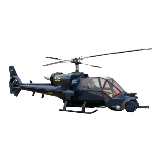
- Page 1 TF Model 700 size Blue Thunder...
-
Page 2: Equipment Recommendations
Thank you for choosing our 700 Blue Thunder. Please read through the instruction manual carefully before proceeding with the assembly of the model.Please note that due to the extensive details associated with this product the instruction manual is divided into two parts, one for the mechanic and one for the assembly of the accessories. - Page 3 Gun turret components, 20mm Vulcan cannon, microphone turret, Spotlights, IR sensor turret, side sensors components and landing gear struts. L:anding gear gluing jig and landing gear struts wood bearer rings. Tail rotor Esc with instructions, one set of bullet connectors, fuselage stays components, tail fixing screws and blind nuts, and extended rotor head pushrods.
- Page 4 One set of laser cut window panels. Screws for securing window panels, access panels and landing skid securing screws. Pre Assembly Preparations Before assembly please solder all the motor and ESC and battery bullet connectors to the tail motor and tail motor ESC. Motor to ESC connectors are supplied.
- Page 5 Tail Fenestron Assembly The tail fenestron unit comes preassembled from the factory, so only minor assembly is required. Locate the 3 claw nuts supplied and drill 3 holes in the tail for the 3 3mm nuts. Following photo is a guideline for locating the 3 holes.
- Page 6 Landing Skid Assembly Locate the 4 landing skid cross members. Also locate and assemble the landing gear gluing jig supplied with the model. The cross members are the same for both left and right side. The longer cross member is for the rear and the shorter one for the front. Landing Skid gluing jig former.
- Page 7 After placing the gluing jig under the main fuselage, align the front of the jig with the front of the fuselage rectangular protrusion on the fuselage bottom. See photo. Locate the skid cross member reinforcement rings as in photo. You need 3 rings per cross member.
- Page 8 Arrangement of the reinforcement rings. Same for all four sides. Once the desired landing skid height and location is set , use ample epoxy to glue the reinforcement rings at the location shown on the following photos. Arrows shows the locations for gluing the reinforcement rings.
- Page 9 Now locatethe supplied wire meah and glue it on the inside of the two openingson the side and st the rear of the main fuselage. Installing Mechanics On your mechanic, remove the tail boom from the tail boom holder and set aside the unused screws.
- Page 10 Disconnect the swashplate side ball links and slide the mechanics into the main fuselage. Align the mechanic mounting holes with the pre drilled holes on the factory installed base board. Ypou might need to trim the area on the top of the main fuselage for your mechanic's mounting holes to line up with the base board holes.
- Page 11 Install the rudder servo into the preinstalled rudder servo plate inside the tail. The rudder pushrod is preinstalled as well. You need only fine tune the length for your specific servo only. Preinstalled servo plate. The installed rudder servo. At this point of the assembly, TF Model highly recommend that you test fly the basic airframe first to get the setting adjusted to your style of flying and to get used to the handling characteristic of this new independent tail drive system.(ITDS) Setting up of the ITDS for first test flight.
- Page 12 For the tail motor drive system we recommend the use of a separate 4s Lipo of 2500mah capacity. The factory matched ESC and motor for the fenestron operates best on 4s. Battery Pluggin In Procedure Before your first flight here is the recommended procedure for plugging in the batteries. 1.
Need help?
Do you have a question about the 700 Blue Thunder and is the answer not in the manual?
Questions and answers